EP0171672A2 - Plot de construction - Google Patents
Plot de construction Download PDFInfo
- Publication number
- EP0171672A2 EP0171672A2 EP85109275A EP85109275A EP0171672A2 EP 0171672 A2 EP0171672 A2 EP 0171672A2 EP 85109275 A EP85109275 A EP 85109275A EP 85109275 A EP85109275 A EP 85109275A EP 0171672 A2 EP0171672 A2 EP 0171672A2
- Authority
- EP
- European Patent Office
- Prior art keywords
- zone
- stud
- insulating
- expanded
- carrier
- Prior art date
- Legal status (The legal status is an assumption and is not a legal conclusion. Google has not performed a legal analysis and makes no representation as to the accuracy of the status listed.)
- Granted
Links
- 230000005540 biological transmission Effects 0.000 claims abstract description 15
- 239000004567 concrete Substances 0.000 claims abstract description 13
- 238000010276 construction Methods 0.000 claims abstract description 13
- 229920003002 synthetic resin Polymers 0.000 claims abstract description 8
- 239000000057 synthetic resin Substances 0.000 claims abstract description 8
- 239000004568 cement Substances 0.000 claims abstract description 6
- 239000011230 binding agent Substances 0.000 claims abstract description 5
- 239000012764 mineral filler Substances 0.000 claims abstract description 5
- 230000006835 compression Effects 0.000 claims abstract description 4
- 238000007906 compression Methods 0.000 claims abstract description 4
- 239000002893 slag Substances 0.000 claims description 6
- 239000000463 material Substances 0.000 claims description 5
- 239000011324 bead Substances 0.000 claims description 4
- 230000001413 cellular effect Effects 0.000 claims description 4
- 239000004927 clay Substances 0.000 claims description 4
- 230000008878 coupling Effects 0.000 claims description 4
- 238000010168 coupling process Methods 0.000 claims description 4
- 238000005859 coupling reaction Methods 0.000 claims description 4
- 239000011521 glass Substances 0.000 claims description 4
- 239000008262 pumice Substances 0.000 claims description 4
- 239000004575 stone Substances 0.000 claims description 3
- 239000004925 Acrylic resin Substances 0.000 claims description 2
- 229920000178 Acrylic resin Polymers 0.000 claims description 2
- 239000008187 granular material Substances 0.000 claims description 2
- 239000010445 mica Substances 0.000 claims description 2
- 229910052618 mica group Inorganic materials 0.000 claims description 2
- 229920002635 polyurethane Polymers 0.000 claims description 2
- 239000004814 polyurethane Substances 0.000 claims description 2
- 229910052902 vermiculite Inorganic materials 0.000 claims description 2
- 239000010455 vermiculite Substances 0.000 claims description 2
- 235000019354 vermiculite Nutrition 0.000 claims description 2
- 239000002023 wood Substances 0.000 claims description 2
- 239000004793 Polystyrene Substances 0.000 claims 1
- 229920002223 polystyrene Polymers 0.000 claims 1
- 238000004453 electron probe microanalysis Methods 0.000 description 4
- KJPHTXTWFHVJIG-UHFFFAOYSA-N n-ethyl-2-[(6-methoxypyridin-3-yl)-(2-methylphenyl)sulfonylamino]-n-(pyridin-3-ylmethyl)acetamide Chemical compound C=1C=C(OC)N=CC=1N(S(=O)(=O)C=1C(=CC=CC=1)C)CC(=O)N(CC)CC1=CC=CN=C1 KJPHTXTWFHVJIG-UHFFFAOYSA-N 0.000 description 4
- 241001639412 Verres Species 0.000 description 2
- 239000003513 alkali Substances 0.000 description 2
- 230000000694 effects Effects 0.000 description 2
- 238000009413 insulation Methods 0.000 description 2
- 230000010363 phase shift Effects 0.000 description 2
- 239000011505 plaster Substances 0.000 description 2
- 239000002585 base Substances 0.000 description 1
- 239000011083 cement mortar Substances 0.000 description 1
- 239000011248 coating agent Substances 0.000 description 1
- 238000000576 coating method Methods 0.000 description 1
- 239000000470 constituent Substances 0.000 description 1
- 239000007799 cork Substances 0.000 description 1
- -1 crushed terracotta Substances 0.000 description 1
- 230000003292 diminished effect Effects 0.000 description 1
- 239000004794 expanded polystyrene Substances 0.000 description 1
- 239000011810 insulating material Substances 0.000 description 1
- 239000012212 insulator Substances 0.000 description 1
- 238000004519 manufacturing process Methods 0.000 description 1
- 239000000203 mixture Substances 0.000 description 1
- 239000004570 mortar (masonry) Substances 0.000 description 1
- XLYOFNOQVPJJNP-UHFFFAOYSA-N water Substances O XLYOFNOQVPJJNP-UHFFFAOYSA-N 0.000 description 1
- 230000003313 weakening effect Effects 0.000 description 1
Images


Classifications
-
- E—FIXED CONSTRUCTIONS
- E04—BUILDING
- E04C—STRUCTURAL ELEMENTS; BUILDING MATERIALS
- E04C1/00—Building elements of block or other shape for the construction of parts of buildings
- E04C1/40—Building elements of block or other shape for the construction of parts of buildings built-up from parts of different materials, e.g. composed of layers of different materials or stones with filling material or with insulating inserts
- E04C1/41—Building elements of block or other shape for the construction of parts of buildings built-up from parts of different materials, e.g. composed of layers of different materials or stones with filling material or with insulating inserts composed of insulating material and load-bearing concrete, stone or stone-like material
Definitions
- the present invention relates to a building block, and more particularly to a monolithic building block having two distinct zones in its thickness.
- Construction studs are already known, for example made of concrete, which are coated on at least one of their faces with an insulating layer.
- This insulating layer can be composed of grains made of an insulating material such as cork coated in a cement mortar, as described in patent FR 2,237,018, or else by multicellular concrete as described in patent BE 480,990.
- the object of this invention therefore consists in providing a building block of the aforementioned type which obviates the aforementioned drawback, that is to say which can be used as a load-bearing element and which has a heat transmission coefficient k less than that of the studs known from the prior art.
- the first load-bearing zone consists of a light concrete, possibly of a synthetic resin, the concrete itself being composed of a normal cement binding a light material such as blast furnace slag, pumice stone, crushed terracotta, clay, clay or expanded shale, pozzolan, etc.
- this material depends on the characteristics sought for the construction stud: for example, an expanded slag will preferably be used to obtain a stud having a high resistance to compression (of the order of 165 kg / cm 2 for a density apparent of approximately 1250 kg / m 3 ), whereas pumice stone will be used preferentially to obtain a stud having better insulation characteristics, but a lower resistance to compression (of the order of 40 kg / cm 2 for an apparent density of around 1000 kg / m 3 ).
- the second insulating zone is preferably composed of a hydraulic binder, for example a cement, and a synthetic resin, coating an expanded mineral filler, for example beads of expanded or cellular glass, vermiculite, polyurethane granules, mica or expanded polystyrene, wood chips, etc.
- a hydraulic binder for example a cement
- a synthetic resin coating an expanded mineral filler, for example beads of expanded or cellular glass, vermiculite, polyurethane granules, mica or expanded polystyrene, wood chips, etc.
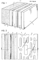
- the illustrated construction stud is of the concrete block type and comprises a load-bearing zone 1 made of light concrete as described above and an insulating zone 2 also produced as described above.
- the thickness of the insulating zone 2 constitutes at least 40% of the total thickness of the pad, while remaining less than that of the carrier zone 1.
- the bearing zone 1 has blind cylindrical voids, for example of sections respectively in the form of slots with rounded ends 3, of rectangles with rounded angles 3 ′, circular 3 ", etc.
- these different voids are arranged as illustrated in the figure 2, that is to say staggered in the thickness of zone 1, so as to provide the best possible resistance to heat transmission.
- the volume occupied by these voids 3.3 ′, 3 ′′ corresponds approximately 25% of the total volume of the carrier zone 1.
- each of the carrier zones 1 and insulator 2 has coupling grooves 4,5 making it possible to ensure better stacking of the construction studs.
- FIG. 4 is schematically illustrated in plan an embodiment of an "interior" angle with two pads A and B each formed by a carrier zone 1 and an insulating zone 2.2 ', the insulating zone 2' of the pad B does not extend, on one side of said stud, to the end of the latter,
- the angle connection between the two studs A and B is formed by an angle core 6, which has a portion 6 'taking the place of the missing portion of the insulating zone 2' of the pad B.
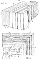
- an "external" corner stud is illustrated, which is formed of a carrier zone 7 of generally rectangular shape and of an insulating zone 8 bordering said carrier zone 7 on two of its adjacent sides.
- the carrier zone 7 has blind voids 3.3 ′, 3 ′′ and coupling grooves 9.9 ′, while the insulating zone 8 also has coupling grooves 10.
- Such values are entirely suitable for allowing the construction of a wall, using the studs according to the invention, whose heat transmission coefficient k is equal to or less than 0.4 (including the external plasters and internal, and the seals).
- the graph in FIG. 7 represents, for the wall described by way of example, the temperature curve across the thickness thereof, from the outside to the inside.
- the interior transmission 1 1.3 ° K according to the EMPA standard is not indicated.
- phase shift is understood here to mean the time between the moment when the cold (or heat) penetrates from the outside and the observation of this change in temperature inside a room; if possible, this duration should be more than 10-12 hours, so that the effects of this difference in phase (or temperature) are not reflected on the other side of the wall (inside) until these effects have diminished significantly or disappeared outside.
- the shapes and dimensions of the blind cells practiced in the area carrying the stud are not limited; on the other hand, it has been shown that the configuration illustrated for example in FIG. 2 was the one which offered the most resistance to heat transmission.
Landscapes
- Engineering & Computer Science (AREA)
- Architecture (AREA)
- Civil Engineering (AREA)
- Structural Engineering (AREA)
- Building Environments (AREA)
- Dowels (AREA)
- Road Signs Or Road Markings (AREA)
- Vending Machines For Individual Products (AREA)
- Electronic Switches (AREA)
- Control Of Vending Devices And Auxiliary Devices For Vending Devices (AREA)
- Semiconductor Integrated Circuits (AREA)
- Bipolar Transistors (AREA)
- External Artificial Organs (AREA)
- Laminated Bodies (AREA)
- Pharmaceuticals Containing Other Organic And Inorganic Compounds (AREA)
- Saccharide Compounds (AREA)
- Buildings Adapted To Withstand Abnormal External Influences (AREA)
Abstract
Description
- La présente invention se rapporte à un plot de construction, et plus particulièrement à un plot de construction monolithique comportant deux zones distinctes dans son épaisseur.
- On connaît déjà des plots de construction, par exemple en béton, qui sont revêtus sur au moins une de leur face d'une couche isolante. Cette couche isolante peut être composée de grains en un matériau isolant tel que du liège enrobé dans un mortier de ciment, comme décrit dans le brevet FR 2.237.018, ou bien par du béton multicellulaire comme décrit dans le brevet BE 480.990. Toutefois, il n'est pas possible avec de tels plots d'obtenir un coefficient de transmission de chaleur k qui soit suffisamment bas pour satisfaire aux exigences actuelles d'isolation des bâtiments. En effet, une augmentation trop importante de la couche isolante au détriment du plot en béton conduirait à un affaiblissement de celui-ci qui ne pourrait alors plus être utilisé pour la réalisation de murs porteurs.
- Le but de cette invention consiste donc à fournir un plot de construction du type précité qui obvie à l'inconvénient précité, c'est-à-dire qui puisse être utilisé comme élément porteur et qui présente un coefficient de transmission de chaleur k inférieur à celui des plots connus de l'art antérieur.
- Le plot de construction selon l'invention qui vise à atteindre le but précité, est caractérisé par le fait que la première zone est porteuse, présente des vides de forme cylindrique ayant en section des extrémités arrondies et est formée d'un béton léger présentant une résistance à la compression comprise entre 25 et 175 kg/cm2 et une densité apparente comprise entre 900 et 1250 kg/m3; par le fait que la seconde zone est isolante, pleine, et d'une densité apparente d'au plus 270 kg/m3, et qu'elle est constituée d'un liant hydraulique à base de ciment, d'une résine synthétique et d'une charge minérale expansée, l'épaisseur de la zone porteuse étant plus grande que celle de la zone isolante; et par le fait que le coefficient de transmission de chaleur k dans le sens perpendiculaire auxdites zones du plot monolithique est égal ou inférieur à k = 0,40 (W/mK).
- De préférence, la première zone porteuse consiste en un béton léger, éventuellement d'une résine synthétique, le béton étant lui-même composé d'un ciment normal liant un matériau léger tel que du laitier de haut-fourneau, de la pierre ponce, de la terre cuite concassée, de l'argile, glaise ou schiste expansé, de la pouzzolane, etc. Le choix de ce matériau dépend des caractéristiques recherchées pour le plot de construction: par exemple, on utilisera de préférence un laitier expansé pour obtenir un plot ayant une résistance élevée à la compression (de l'ordre de 165 kg/cm2 pour une densité apparente d'environ 1250 kg/m3), alors que la pierre ponce sera utilisée préférentiellement pour obtenir un plot ayant de meilleures caractéristiques d'isolation, mais une résistance moins élevée à la compression (de l'ordre de 40 kg/cm2 pour une densité apparente d'environ 1000 kg/m3).
- Quant à la seconde zone isolante, elle est de préférence composée d'un liant hydraulique par exemple un ciment, et d'une résine synthétique, enrobant une charge minérale expansée, par exemple des billes de verre expansé ou cellulaire, de la vermiculite, des granulés de polyuréthane, du mica ou du polystyrène expansé, des copeaux de bois, etc.
- Le dessin annexé illustre l'invention schématiquement et à titre d'exemples.
- La figure 1 est une vue en perspective de dessus d'un plot de construction selon l'invention.
- La figure 2 est une vue en plan de dessous du plot selon la figure 1, et la figure 3 est une vue en coupe selon la ligne III-III de la figure 2.
- La figure 4 est une vue en plan de dessus d'une réalisation d'un angle intérieur avec deux plots de construction selon l'invention.
- La figure 5 est une vue en plan de dessus d'un plot d'angle, et la figure 6 est une vue en plan de dessous de ce plot d'angle.
- La figure 7 est un graphique représentant la transmission de chaleur (température en fonction de l'épaisseur) à travers un mur réalisé avec des plots selon l'invention.
- En référence tout d'abord aux figures 1 à 3, le plot de construction illustré est du type parpaing et comporte une zone porteuse 1 réalisée en béton léger comme décrit précédemment et une zone isolante 2 également réalisée comme décrit ci-dessus. De préférence, l'épaisseur de la zone isolante 2 constitue au moins le 40 % de l'épaisseur totale du plot, tout en restant inférieure à celle de la zone porteuse 1.
- La zone porteuse 1 présente des vides cylindriques borgnes par exemple de sections respectivement en forme de fentes à extrémités arrondies 3, de rectangles à angles arrondis 3', circulaires 3", etc. De préférence, ces différents vides sont disposés comme illustrés sur la figure 2, c'est-à-dire en quinconce dans l'épaisseur de la zone 1, de manière à fournir la meilleure résistance possible à la transmission de la chaleur. Le volume occupé par ces vides 3,3',3'' correspond approximativement au 25 % du volume total de la zone porteuse 1.
- De plus, chacune des zones porteuses 1 et isolante 2 présente des gorges d'accouplement 4,5 permettant d'assurer un meilleur empilage des plots de construction.
- Sur la figure 4 est illustrée schématiquement en plan une réalisation d'un angle "intérieur" avec deux plots A et B formés chacun d'une zone porteuse 1 et d'une zone isolante 2,2', la zone isolante 2' du plot B ne s'étendant pas, d'un côté dudit plot, jusqu'à l'extrémité de celui-ci, La liaison d'angle entre les deux plots A et B est formée par un noyau d'angle 6, qui présente une portion 6' prenant la place de la portion manquante de la zone isolante 2' du plot B.
- Enfin, en référence aux figures 5 et 6, un plot d'angle "extérieur" est illustré, qui est formé d'une zone porteuse 7 de forme générale rectangulaire et d'une zone isolante 8 bordant ladite zone porteuse 7 sur deux de ses côtés adjacents. Comme dans le cas du plot simple, la zone porteuse 7 présente des vides borgnes 3,3',3'' et des gorges d'accouplement 9,9', alors que la zone isolante 8 présente également des gorges d'accouplement 10.
- Les plots de construction selon l'invention, tels que décrits ci-dessus à titre d'exemples, présentent un coefficient de transmission de chaleur k inférieur à environ 0,35 W/mK (1 W/mK = 0,860 kcal / mh°C); par exemple, avec une zone porteuse réalisée à base de laitier expansé (densité = environ 1250 kg/m3), on obtient un k d'environ 0,3, alors qu'avec une zone porteuse à base de pierre ponce, le k du plot obtenu est de l'ordre de 0,25. De telles valeurs sont tout-à-fait appropriées pour permettre la construction d'un mur, en utilisant les plots selon l'invention, dont le coefficient de transmission de chaleur k est égal ou inférieur à 0,4 (y compris les crépis externe et interne, et les joints).
- A titre d'exemple, on présentera ci-après les caractéristiques de transmission de chaleur d'l m2 de mur de 38,5 cm d'épaisseur totale, réalisé avec des plots selon l'invention d'une épaisseur de 35 cm, et comprenant les constituants suivants de l'extérieur vers l'intérieur ainsi que 5 joints horizontaux :
- - crépi extérieur : 2 cm (À = 0,87 W/mK)
- - plot selon l'invention :
- . zone isolante comportant des billes de verre cellulaire : 15 cm (λ = 0,078 W/mK) voir "Calcul pondéré" plus loin. Le matériau "SILIPERL" ayant un lambda de 0,075 W/mK ne résiste pas à l'alcali, c'est pour cette raison que nous avons tenu compte dans le "Calcul pondéré" seulement du matériau "DENNERT" résistant à l'alcali selon le test EMPA Nr. 48 374/1 et présentant un lambda de 0,078 W/mK.
- . zone porteuse à base de laitier expansé bouleté : 20 cm (λ = 0,30 W/mK)
- ― crépi intérieur : 1,5 cm (À = 0,70 W/mK).
- Dans l'exemple ci-dessus, le plot lui-même présente un coefficient de transmission de chaleur k = 0,386. La composition des différentes parties du mur est la suivante :
- a) Plot selon l'invention
- - Zone porteuse (20 cm d'épaisseur) Laitier de haut-fourneau expansé bouleté (type "GALEX")

Ce coefficient eau/ciment
- - Zone isolante (15 cm d'épaisseur) Billes de verre cellulaire résistantes

* Les résines synthétiques sont des résines acryliques, par exemple du type "UCECRYL" (de la Société UCB), "D 510" et "B 500" (de ROEHM et HAAS) etc.
- - Zone porteuse (20 cm d'épaisseur) Laitier de haut-fourneau expansé bouleté (type "GALEX")
- b) Joints en mortier isolant

- Dans le tableau ci-dessous, le calcul pondéré selon les normes EMPA de transmission de chaleur est présenté dans le cas du mur décrit précédemment, et pour une différence de température entre la face froide externe (-10°C) et la face chaude interne (+20°C) de 30° :
- Tableau du calcul de k :


- 0,393 W/m2 K pourrait encore être améliorée en utilisant des enduits isolants sur les crépis normaux ou à la place de ceux-ci.
- Enfin, le graphique de la figure 7 représente pour le mur décrit à titre d'exemple la courbe de température à travers l'épaisseur de celui-ci, de l'extérieur vers l'intérieur. Dans ce graphique, la transmission intérieure 1 = 1,3°K selon la norme EMPA n'est pas indi-8 quée.
- En outre, grâce au coefficient de transmission de chaleur k très bas que présentent les plots de construction selon l'invention, un mur réalisé avec ceux-ci montrera un décalage de phase supérieur à environ 14 heures. Par décalage de phase, on entend ici la durée entre le moment de la pénétration depuis l'extérieur du froid (ou de la chaleur) et l'observation de cette modification de température à l'intérieur d'une chambre; cette durée doit être si possible supérieure à 10-12 heures, de telle sorte que les effets de cette différence de phase (ou de température) ne se répercutent de l'autre côté du mur (à l'intérieur) qu'au moment où ces effets ont diminué sensiblement ou ont disparu à l'extérieur.
- Enfin, les formes et les dimensions des alvéoles borgnes pratiquées dans la zone porteuse du plot ne sont pas limitées; par contre, il a été démontré que la configuration illustrée par exemple sur la figure 2 était celle qui offrait le plus de résistance à la transmission de chaleur.
Claims (11)
Priority Applications (1)
| Application Number | Priority Date | Filing Date | Title |
|---|---|---|---|
| AT85109275T ATE53092T1 (de) | 1984-08-15 | 1985-07-24 | Baublock. |
Applications Claiming Priority (2)
| Application Number | Priority Date | Filing Date | Title |
|---|---|---|---|
| CH3914/84 | 1984-08-15 | ||
| CH3914/84A CH658283A5 (fr) | 1984-08-15 | 1984-08-15 | Plot de construction. |
Publications (3)
| Publication Number | Publication Date |
|---|---|
| EP0171672A2 true EP0171672A2 (fr) | 1986-02-19 |
| EP0171672A3 EP0171672A3 (en) | 1987-04-01 |
| EP0171672B1 EP0171672B1 (fr) | 1990-05-23 |
Family
ID=4266212
Family Applications (1)
| Application Number | Title | Priority Date | Filing Date |
|---|---|---|---|
| EP85109275A Expired - Lifetime EP0171672B1 (fr) | 1984-08-15 | 1985-07-24 | Plot de construction |
Country Status (16)
| Country | Link |
|---|---|
| US (1) | US4641470A (fr) |
| EP (1) | EP0171672B1 (fr) |
| JP (1) | JPS6160944A (fr) |
| AT (1) | ATE53092T1 (fr) |
| AU (1) | AU575670B2 (fr) |
| CA (1) | CA1243215A (fr) |
| CH (1) | CH658283A5 (fr) |
| DE (2) | DE3577897D1 (fr) |
| DK (1) | DK163680C (fr) |
| ES (1) | ES295961Y (fr) |
| FI (1) | FI79378C (fr) |
| GR (1) | GR851975B (fr) |
| IL (1) | IL76080A0 (fr) |
| NO (1) | NO168661C (fr) |
| PT (1) | PT80924B (fr) |
| ZA (1) | ZA855894B (fr) |
Cited By (4)
| Publication number | Priority date | Publication date | Assignee | Title |
|---|---|---|---|---|
| FR2663065A1 (fr) * | 1990-06-12 | 1991-12-13 | Neveux Francois | Parpaing de construction leger, isolant thermique, porteur. |
| EP0688261A4 (fr) * | 1993-03-08 | 1998-04-01 | Khashoggi E Ind | Barrieres isolantes a matrice durcissable hydrauliquement |
| KR100810644B1 (ko) * | 2007-04-19 | 2008-03-06 | 삼성에스디아이 주식회사 | 유기전계발광소자 및 그의 제조 방법 |
| WO2013091645A1 (fr) * | 2011-12-19 | 2013-06-27 | A/S Graasten Teglværk | Combinaison de blocs de construction |
Families Citing this family (20)
| Publication number | Priority date | Publication date | Assignee | Title |
|---|---|---|---|---|
| USD302312S (en) | 1985-10-09 | 1989-07-18 | The Dow Chemical Company | Corner block |
| US4724427A (en) * | 1986-07-18 | 1988-02-09 | B. I. Incorporated | Transponder device |
| US4879849A (en) * | 1987-11-04 | 1989-11-14 | Omni Films International, Inc. | Point-of-view motion simulator system |
| GB9108592D0 (en) * | 1991-04-22 | 1991-06-05 | Hepworth Building Prod | Building block |
| USD346031S (en) | 1991-12-19 | 1994-04-12 | Rothbury Investments Limited | Modular block |
| AU665695B2 (en) * | 1992-07-08 | 1996-01-11 | Yves Pierre Marcel Treuil | Cementitious building element |
| WO1995002561A1 (fr) * | 1993-07-16 | 1995-01-26 | Rigro, Inc. | Procede d'utilisation de beton leger permettant de produire un combinaison de ce materiau, et combinaison produite par ce procede |
| DE29601827U1 (de) * | 1996-02-03 | 1996-03-14 | Gebhart, Siegfried, 88317 Aichstetten | Stein, insbesondere Schalungs- oder Blockstein |
| USH2063H1 (en) | 2000-03-13 | 2003-05-06 | The United States Of America As Represented By The Secretary Of The Navy | Thermal barrier and method of use |
| US20030092848A1 (en) * | 2001-09-11 | 2003-05-15 | Ashok Sengupta | Sprayable liner for supporting the rock surface of a mine |
| USD512162S1 (en) * | 2004-05-26 | 2005-11-29 | Jagna Ltd. | Wall retaining block |
| FR2881423B1 (fr) * | 2005-02-02 | 2007-04-20 | Henri Clervil | Composition pour beton isolant, element de construction pour la realisation d'un coffrage perdu realise avec ce beton, coffrage perdu realise a partir de ces elements et paroi porteuse realisee |
| KR100793542B1 (ko) * | 2006-10-12 | 2008-01-14 | 삼성에스디아이 주식회사 | 유기전계발광표시장치 및 그의 구동방법 |
| US8991124B2 (en) * | 2008-10-17 | 2015-03-31 | Schöck Bauteile GmbH | Concrete material, construction element for a thermal insulation, and brick-shaped thermally insulating element, each using the concrete material |
| DE102010023708A1 (de) * | 2010-06-14 | 2011-12-15 | Fensterle Bauunternehmen Gmbh | Bauteil für ein Gebäude, insbesondere Wand-, Decken- oder Dachelementbauteil, und zugehöriges Herstellungsverfahren |
| NL2014985B1 (nl) | 2014-06-20 | 2016-12-06 | Ceves-Vergeer B V | Droog mortelmengsel met korrels van geëxpandeerd glas. |
| US9447578B2 (en) | 2015-01-02 | 2016-09-20 | Richard Nelson DeBoer | Modular block wall system |
| US10626599B2 (en) * | 2016-01-06 | 2020-04-21 | David NEGEV | Interlocking masonry brick |
| FR3075234B1 (fr) * | 2017-12-20 | 2020-01-17 | Haidar Ben Raffion | Bloc de construction |
| CN108627536B (zh) * | 2018-04-04 | 2020-06-16 | 长安大学 | 一种浇注式导电沥青混凝土传导热效果预估方法 |
Family Cites Families (11)
| Publication number | Priority date | Publication date | Assignee | Title |
|---|---|---|---|---|
| BE480990A (fr) * | ||||
| FR2189601A1 (fr) * | 1972-06-16 | 1974-01-25 | Gasse Et Cie Eu Omat | |
| FR2237018A1 (en) * | 1973-06-22 | 1975-02-07 | Grisard Paul | Aggregate building block with partially insulated surface - comprising a layer of thermally insulated particles bound by cement |
| US4263372A (en) * | 1976-05-19 | 1981-04-21 | Rohm And Haas Company | Method of coating and/or impregnating porous substrates, and products obtained thereby |
| US4309325A (en) * | 1976-07-13 | 1982-01-05 | Societe Metallurgique De Bretagne | Clay-cement mortars and to the product made with said mortars |
| US4372092A (en) * | 1976-08-16 | 1983-02-08 | Lopez Fred T | Precast concrete modular building panel |
| US4130973A (en) * | 1977-09-07 | 1978-12-26 | Curt Holger Ingestrom | Building block |
| FR2456179A1 (fr) * | 1978-07-19 | 1980-12-05 | Costamagna & Cie B M | Procede de construction, produit prefabrique pour sa mise en oeuvre et mode de fabrication dudit produit |
| FR2442930A2 (fr) * | 1978-11-30 | 1980-06-27 | Grisard Paul | Bloc en agglomeres de beton ou en brique avec enduit isolant incorpore |
| FR2446704A1 (fr) * | 1979-01-19 | 1980-08-14 | Monestier Claude | Materiau de construction et son procede de fabrication |
| DE2914647A1 (de) * | 1979-04-11 | 1980-10-30 | Basf Ag | Hohlblockstein mit integrierter waermedaemmschicht |
-
1984
- 1984-08-15 CH CH3914/84A patent/CH658283A5/fr not_active IP Right Cessation
-
1985
- 1985-07-24 DE DE8585109275T patent/DE3577897D1/de not_active Expired - Lifetime
- 1985-07-24 AT AT85109275T patent/ATE53092T1/de active
- 1985-07-24 EP EP85109275A patent/EP0171672B1/fr not_active Expired - Lifetime
- 1985-07-24 DE DE198585109275T patent/DE171672T1/de active Pending
- 1985-07-31 US US06/761,228 patent/US4641470A/en not_active Expired - Fee Related
- 1985-08-01 CA CA000487943A patent/CA1243215A/fr not_active Expired
- 1985-08-05 ZA ZA855894A patent/ZA855894B/xx unknown
- 1985-08-06 PT PT80924A patent/PT80924B/pt not_active IP Right Cessation
- 1985-08-12 FI FI853086A patent/FI79378C/fi not_active IP Right Cessation
- 1985-08-13 DK DK366285A patent/DK163680C/da not_active Application Discontinuation
- 1985-08-13 ES ES1985295961U patent/ES295961Y/es not_active Expired
- 1985-08-13 GR GR851975A patent/GR851975B/el unknown
- 1985-08-13 NO NO853185A patent/NO168661C/no unknown
- 1985-08-13 IL IL76080A patent/IL76080A0/xx unknown
- 1985-08-14 AU AU46195/85A patent/AU575670B2/en not_active Ceased
- 1985-08-14 JP JP60177763A patent/JPS6160944A/ja active Pending
Cited By (4)
| Publication number | Priority date | Publication date | Assignee | Title |
|---|---|---|---|---|
| FR2663065A1 (fr) * | 1990-06-12 | 1991-12-13 | Neveux Francois | Parpaing de construction leger, isolant thermique, porteur. |
| EP0688261A4 (fr) * | 1993-03-08 | 1998-04-01 | Khashoggi E Ind | Barrieres isolantes a matrice durcissable hydrauliquement |
| KR100810644B1 (ko) * | 2007-04-19 | 2008-03-06 | 삼성에스디아이 주식회사 | 유기전계발광소자 및 그의 제조 방법 |
| WO2013091645A1 (fr) * | 2011-12-19 | 2013-06-27 | A/S Graasten Teglværk | Combinaison de blocs de construction |
Also Published As
| Publication number | Publication date |
|---|---|
| NO168661B (no) | 1991-12-09 |
| IL76080A0 (en) | 1985-12-31 |
| AU575670B2 (en) | 1988-08-04 |
| FI853086A0 (fi) | 1985-08-12 |
| CA1243215A (fr) | 1988-10-18 |
| DE171672T1 (de) | 1986-05-22 |
| ATE53092T1 (de) | 1990-06-15 |
| FI79378B (fi) | 1989-08-31 |
| DK163680C (da) | 1992-08-10 |
| JPS6160944A (ja) | 1986-03-28 |
| NO168661C (no) | 1992-03-18 |
| DK163680B (da) | 1992-03-23 |
| PT80924A (en) | 1985-09-01 |
| EP0171672A3 (en) | 1987-04-01 |
| DK366285A (da) | 1986-02-16 |
| DK366285D0 (da) | 1985-08-13 |
| ES295961U (es) | 1987-12-01 |
| CH658283A5 (fr) | 1986-10-31 |
| GR851975B (fr) | 1985-12-16 |
| NO853185L (no) | 1986-02-17 |
| FI79378C (fi) | 1989-12-11 |
| PT80924B (pt) | 1987-06-17 |
| ZA855894B (en) | 1986-03-26 |
| DE3577897D1 (de) | 1990-06-28 |
| US4641470A (en) | 1987-02-10 |
| ES295961Y (es) | 1988-05-16 |
| FI853086L (fi) | 1986-02-16 |
| EP0171672B1 (fr) | 1990-05-23 |
| AU4619585A (en) | 1986-02-20 |
Similar Documents
| Publication | Publication Date | Title |
|---|---|---|
| EP0171672B1 (fr) | Plot de construction | |
| EP1644461A2 (fr) | Dispositif coupe-feu pour la protection de parois ou de structures ou la realisation d'une enceinte de protection | |
| WO1992009762A1 (fr) | Element et procede de construction sans mortier | |
| EP0088198A2 (fr) | Procédé de réalisation d'une couverture dite "toiture inversée" pour un immeuble et élément préfabriqué pour la réalisation d'une telle couverture | |
| EP1899541A1 (fr) | Rupteur thermique | |
| LU81463A1 (fr) | Procede de construction,produit prefabrique pour sa mise en oeuvre et mode de fabrication dudit produit | |
| WO2014191664A1 (fr) | Conduit de protection incendie | |
| CH572141A5 (en) | Composite structural and insulant building wall block - has parallel opposed face load bearing plaques inter-spaced via rigid bonded bars | |
| CH598442A5 (en) | Brick assembly for building wall | |
| EP1063364B1 (fr) | Mur isolant | |
| WO1984003318A1 (fr) | Mur de construction composite et isolant | |
| FR2511060A1 (fr) | Bloc en forme de t pour parois | |
| FR2477608A1 (fr) | Moellon et son procede de fabrication | |
| FR2971801A1 (fr) | Bloc de beton alveolaire isolant | |
| FR2488303A1 (fr) | Procede de construction de planchers isolants a base d'elements autoportants et elements ainsi que planchers y relatifs | |
| FR2549511A1 (fr) | Panneaux isolants prefabriques pour constructions industrialisees et applications | |
| FR2562121A1 (fr) | Entrevous composite | |
| FR2589909A1 (fr) | Bloc d'agglomere pour maconnerie a isolation thermique integree. | |
| WO2002095158A1 (fr) | Panneau de cloisonnement | |
| FR2622229A1 (fr) | Bloc modulaire de construction | |
| EP0451249A1 (fr) | Elements de construction nouveaux. | |
| FR2556454A1 (fr) | Procede de stockage de l'energie solaire par utilisation d'accumulateurs et de parois en beton lourd | |
| FR2465844A1 (fr) | Perfectionnements apportes aux panneaux prefabriques pour la realisation de constructions notamment a usage d'habitation, ainsi que les constructions faisant application de tels panneaux | |
| FR2560910A1 (fr) | Poutrelle pour plancher isolant | |
| FR2613402A1 (fr) | Panneau de construction porteur comportant une couche d'isolation |
Legal Events
| Date | Code | Title | Description |
|---|---|---|---|
| PUAI | Public reference made under article 153(3) epc to a published international application that has entered the european phase |
Free format text: ORIGINAL CODE: 0009012 |
|
| AK | Designated contracting states |
Designated state(s): AT BE CH DE FR GB IT LI LU NL SE |
|
| ITCL | It: translation for ep claims filed |
Representative=s name: ING. ENRICO LORENZONI |
|
| TCAT | At: translation of patent claims filed | ||
| TCNL | Nl: translation of patent claims filed | ||
| DET | De: translation of patent claims | ||
| PUAL | Search report despatched |
Free format text: ORIGINAL CODE: 0009013 |
|
| AK | Designated contracting states |
Kind code of ref document: A3 Designated state(s): AT BE CH DE FR GB IT LI LU NL SE |
|
| 17P | Request for examination filed |
Effective date: 19870430 |
|
| 17Q | First examination report despatched |
Effective date: 19880819 |
|
| ITF | It: translation for a ep patent filed | ||
| GRAA | (expected) grant |
Free format text: ORIGINAL CODE: 0009210 |
|
| AK | Designated contracting states |
Kind code of ref document: B1 Designated state(s): AT BE CH DE FR GB IT LI LU NL SE |
|
| REF | Corresponds to: |
Ref document number: 53092 Country of ref document: AT Date of ref document: 19900615 Kind code of ref document: T |
|
| REF | Corresponds to: |
Ref document number: 3577897 Country of ref document: DE Date of ref document: 19900628 |
|
| GBT | Gb: translation of ep patent filed (gb section 77(6)(a)/1977) | ||
| PLBE | No opposition filed within time limit |
Free format text: ORIGINAL CODE: 0009261 |
|
| STAA | Information on the status of an ep patent application or granted ep patent |
Free format text: STATUS: NO OPPOSITION FILED WITHIN TIME LIMIT |
|
| 26N | No opposition filed | ||
| ITTA | It: last paid annual fee | ||
| PGFP | Annual fee paid to national office [announced via postgrant information from national office to epo] |
Ref country code: AT Payment date: 19920623 Year of fee payment: 8 |
|
| PGFP | Annual fee paid to national office [announced via postgrant information from national office to epo] |
Ref country code: BE Payment date: 19920625 Year of fee payment: 8 |
|
| PGFP | Annual fee paid to national office [announced via postgrant information from national office to epo] |
Ref country code: SE Payment date: 19920626 Year of fee payment: 8 |
|
| PGFP | Annual fee paid to national office [announced via postgrant information from national office to epo] |
Ref country code: FR Payment date: 19920630 Year of fee payment: 8 |
|
| PGFP | Annual fee paid to national office [announced via postgrant information from national office to epo] |
Ref country code: CH Payment date: 19920716 Year of fee payment: 8 |
|
| PGFP | Annual fee paid to national office [announced via postgrant information from national office to epo] |
Ref country code: LU Payment date: 19920722 Year of fee payment: 8 |
|
| PGFP | Annual fee paid to national office [announced via postgrant information from national office to epo] |
Ref country code: GB Payment date: 19920723 Year of fee payment: 8 |
|
| PGFP | Annual fee paid to national office [announced via postgrant information from national office to epo] |
Ref country code: NL Payment date: 19920731 Year of fee payment: 8 |
|
| PGFP | Annual fee paid to national office [announced via postgrant information from national office to epo] |
Ref country code: DE Payment date: 19920924 Year of fee payment: 8 |
|
| EPTA | Lu: last paid annual fee | ||
| PG25 | Lapsed in a contracting state [announced via postgrant information from national office to epo] |
Ref country code: LU Free format text: LAPSE BECAUSE OF NON-PAYMENT OF DUE FEES Effective date: 19930724 Ref country code: GB Effective date: 19930724 Ref country code: AT Effective date: 19930724 |
|
| PG25 | Lapsed in a contracting state [announced via postgrant information from national office to epo] |
Ref country code: SE Effective date: 19930725 |
|
| PG25 | Lapsed in a contracting state [announced via postgrant information from national office to epo] |
Ref country code: LI Effective date: 19930731 Ref country code: CH Effective date: 19930731 Ref country code: BE Effective date: 19930731 |
|
| BERE | Be: lapsed |
Owner name: BAUMBERGER WERNER Effective date: 19930731 |
|
| PG25 | Lapsed in a contracting state [announced via postgrant information from national office to epo] |
Ref country code: NL Effective date: 19940201 |
|
| NLV4 | Nl: lapsed or anulled due to non-payment of the annual fee | ||
| GBPC | Gb: european patent ceased through non-payment of renewal fee |
Effective date: 19930724 |
|
| PG25 | Lapsed in a contracting state [announced via postgrant information from national office to epo] |
Ref country code: FR Effective date: 19940331 |
|
| REG | Reference to a national code |
Ref country code: CH Ref legal event code: PL |
|
| PG25 | Lapsed in a contracting state [announced via postgrant information from national office to epo] |
Ref country code: DE Effective date: 19940401 |
|
| REG | Reference to a national code |
Ref country code: FR Ref legal event code: ST |
|
| EUG | Se: european patent has lapsed |
Ref document number: 85109275.9 Effective date: 19940210 |