EP0171761A2 - Montage pour installations de télécommunications, en particulier pour centraux téléphoniques comprenant des processeurs d'informations et des compteurs qui reconnaissent la charge de trafic - Google Patents
Montage pour installations de télécommunications, en particulier pour centraux téléphoniques comprenant des processeurs d'informations et des compteurs qui reconnaissent la charge de trafic Download PDFInfo
- Publication number
- EP0171761A2 EP0171761A2 EP85109990A EP85109990A EP0171761A2 EP 0171761 A2 EP0171761 A2 EP 0171761A2 EP 85109990 A EP85109990 A EP 85109990A EP 85109990 A EP85109990 A EP 85109990A EP 0171761 A2 EP0171761 A2 EP 0171761A2
- Authority
- EP
- European Patent Office
- Prior art keywords
- switching
- counter
- indicator
- indicators
- initial
- Prior art date
- Legal status (The legal status is an assumption and is not a legal conclusion. Google has not performed a legal analysis and makes no representation as to the accuracy of the status listed.)
- Granted
Links
Images
Classifications
-
- H—ELECTRICITY
- H04—ELECTRIC COMMUNICATION TECHNIQUE
- H04Q—SELECTING
- H04Q3/00—Selecting arrangements
- H04Q3/42—Circuit arrangements for indirect selecting controlled by common circuits, e.g. register controller, marker
- H04Q3/54—Circuit arrangements for indirect selecting controlled by common circuits, e.g. register controller, marker in which the logic circuitry controlling the exchange is centralised
- H04Q3/545—Circuit arrangements for indirect selecting controlled by common circuits, e.g. register controller, marker in which the logic circuitry controlling the exchange is centralised using a stored program
- H04Q3/54575—Software application
- H04Q3/54591—Supervision, e.g. fault localisation, traffic measurements, avoiding errors, failure recovery, monitoring, statistical analysis
-
- H—ELECTRICITY
- H04—ELECTRIC COMMUNICATION TECHNIQUE
- H04M—TELEPHONIC COMMUNICATION
- H04M3/00—Automatic or semi-automatic exchanges
- H04M3/22—Arrangements for supervision, monitoring or testing
- H04M3/36—Statistical metering, e.g. recording occasions when traffic exceeds capacity of trunks
- H04M3/365—Load metering of control unit
-
- H—ELECTRICITY
- H04—ELECTRIC COMMUNICATION TECHNIQUE
- H04Q—SELECTING
- H04Q2213/00—Indexing scheme relating to selecting arrangements in general and for multiplex systems
- H04Q2213/1302—Relay switches
-
- H—ELECTRICITY
- H04—ELECTRIC COMMUNICATION TECHNIQUE
- H04Q—SELECTING
- H04Q2213/00—Indexing scheme relating to selecting arrangements in general and for multiplex systems
- H04Q2213/1304—Coordinate switches, crossbar, 4/2 with relays, coupling field
-
- H—ELECTRICITY
- H04—ELECTRIC COMMUNICATION TECHNIQUE
- H04Q—SELECTING
- H04Q2213/00—Indexing scheme relating to selecting arrangements in general and for multiplex systems
- H04Q2213/13164—Traffic (registration, measurement,...)
-
- H—ELECTRICITY
- H04—ELECTRIC COMMUNICATION TECHNIQUE
- H04Q—SELECTING
- H04Q2213/00—Indexing scheme relating to selecting arrangements in general and for multiplex systems
- H04Q2213/13166—Fault prevention
-
- H—ELECTRICITY
- H04—ELECTRIC COMMUNICATION TECHNIQUE
- H04Q—SELECTING
- H04Q2213/00—Indexing scheme relating to selecting arrangements in general and for multiplex systems
- H04Q2213/13213—Counting, timing circuits
-
- H—ELECTRICITY
- H04—ELECTRIC COMMUNICATION TECHNIQUE
- H04Q—SELECTING
- H04Q2213/00—Indexing scheme relating to selecting arrangements in general and for multiplex systems
- H04Q2213/1327—Release and resetting of connection
Definitions
- the invention relates to a circuit arrangement for telecommunication systems, in particular telephone switching systems, with central and / or partially central information processing and with a limited capacity in terms of information processing capacity, to which series of switching indicators are delivered, with each series consisting of a first in time There are initial switching indicators and a number of individually associated successor switching indicators that have been announced, and these switching indicators are nested in chronological order in a sequence that is irregular with respect to the different series, and the switching indicators are each accompanied by a series of identical addresses that indicate the respective place of origin of these switching indicators, and with Determination of the information processing traffic load of each switching mechanism and for the detection of information processing V traffic overloads and counters serving to counteract such overloads, which are switched forward by the initial switching indicators and are switched back in regular time intervals according to the information processing capacity, and which, when an upper limit value is reached or exceeded as a result of forward switching, for subsequent initial switching indicators, in particular for a portion of the subsequent ones incoming initial switching indicator and / or a deviation for the initial switching indicator leading to the
- the counter is used to ensure that the inflow of initial switching indicators to a switching mechanism does not on average exceed a value corresponding to its information processing capacity. According to this, the frequency of the control pulses for the downward switching operations of the counter is fixed and set. If initial switching indicators are received partly in a denser and partly in a further sequence, none of them will be rejected if the counter reading does not reach or exceed the upper limit mentioned.
- the level of the above-mentioned upper limit in relation to the zero level of the counter is also important in this context. This height makes it possible to compensate for random fluctuations in the density of incoming initial switching indicators, i.e. to compensate for them, justified by the fact that the subsequent switching indicators individually assigned to these initial switching indicators are scattered with one another anyway with regard to the different series to which they belong, which already compensates regarding the main workload for the rear derailleur. It is therefore necessary to set this upper limit in a correspondingly high level in relation to the zero level of the meter. This amount corresponds to a number of accepted initial switching indicators, as well as a correspondingly larger number of switching indicators still to be processed by the relevant switching mechanism.
- the Subsequent switching indicators are only announced by the accepted initial switching indicators and are therefore not yet pending processing at the relevant time; the initial switching indicators, on the other hand, are already pending for processing. They can be called up successively from the relevant connection-specific switching devices.
- the switching mechanisms are equipped with input buffer memories, into which the switching indicators are entered one after the other in order to be called up successively in the same order from the relevant information processing switching mechanism.
- the object of the invention is to reduce the overload of a corresponding switching mechanism following an accumulation of initial switching indicators in a circuit arrangement of the type specified at the outset as effectively as possible.
- the invention achieves the object in that a high density of initial switching indicators, which leads to reaching the upper limit value, is detected as a signal for an imminent information processing traffic overload caused by subsequent switching indicators with the aid of the counter and a memory which fulfills the criterion that Meter reading on or off ter a lower limit value, stores for a period of time measured from the termination of this criterion, in that an AND gate forms an overload announcement indicator from this criterion pending from the memory and from a signal resulting from reaching the upper limit value, and by means of this a timer is maintained for a period of time measured by the mean time difference between the initial switching indicator and the associated first subsequent switching indicator or by the upper range of the spreading range of this time difference until the overload notification indicator has ended and, when the overload situation occurs, is maintained until the end thereof, and that the overload indicator increases the forward switching of the counter and / or reduces its reverse switching.
- connection-specific devices are, for example, subscriber line circuits; to establish connections serve as connection-specific switching devices dial indicator receivers, internal connection sets, exchange connection sets of exchange connection lines in private branch exchange switching systems, line termination circuits of local and long-distance connection lines and the like.
- central control unit When connections are established, information arrives in subscriber-specific and connection-specific switching devices, which are to be processed by the central control unit of the relevant telephone switching system or by one of its sub-control units.
- central control unit represents a simplification in the way of labeling; this is preferably a coordination processor.
- the entire control process is decentralized as far as possible and distributed to sub-control units.
- the information arriving in subscriber-specific and usage-specific switching devices represents information processing requirements for the central control unit, which involves the establishment, maintenance and termination of individual message connections, for example telephone connections, and correct processing of billing information, for example billing counts.
- Information processing requests on the part of subscriber stations can be the subscriber call initiating the establishment of a connection or also dialing indicators subsequently given, which may correspond to the individual digits of a telephone number.
- Information processing requests that arrive from a line termination circuit of an incoming connection line can be the switching indicator of an incoming assignment or an incoming dialing indicator. If an outgoing line is seized, the dialing end indicator, the starting signal and billing counts can arrive contrary to the connection establishment direction.
- These switching indicators therefore arrive in a line termination circuit of an outgoing busy connecting line and also result in information processing requests which the respectively occupied line termination circuit to the relevant central control unit or
- Sub-control unit gives out.
- the information processing requirements caused by each of the switching labels listed above are based on nothing but individual switching labels that arrive in the various switching devices from the start of a connection establishment until the complete establishment of a connection, and also during the existence of the same connection and until it is finally triggered.
- All switching indicators that each belong to a single connection form a series.
- the first switching indicator of such a series is an initial switching indicator.
- a series of switching indicators consists of a number of individually associated successor indicators that are announced by the relevant initial switching indicator.
- the switching indicators belonging to the various connections now arrive at the respective telecommunications switching system in a sequence which is irregular with respect to the different series and nested in time with respect to the different series. In the same way (with regard to the irregular sequence and the nesting into one another), these switching indicators are received unchanged or - preferably - after a suitable implementation at the central control unit concerned and represent information processing requirements here.
- All switching indicators have a specific place of origin. They come from one of the connection-specific switching devices. Each of them is identified by its own origin address. The relevant origin address is attached to each switching indicator or processing request. As a result, all switching indicators of a series each have the same source addresses.
- Central control units or partial control units are therefore central or partial central information processing switching units; they have limited performance in terms of information processing capacity.
- the occurrence of information processing requests relating to such a control unit is random and depends on the respective subscriber behavior of each of the subscribers involved in the large number of the connections concerned and is subject to statistical distribution in a known manner.
- the information processing load is therefore always a fluctuating variable.
- the central control unit of a telecommunications switching system or the relevant sub-control units which naturally have a finite performance capacity in terms of information processing capacity, are adapted in terms of their performance capability to the requirements that arise in each case. Such an adjustment of the information processing capacity to the constantly fluctuating information processing load is subject to various requirements.
- devices are set up in connection with central control units or partial control units provided for determining the information processing traffic load of such a control unit and for detecting information processing traffic overloads and for warding off such overloads.
- Such devices are also designed, among other things, as counters which are switched forward by the incoming switching indicators and which are switched back again at regular intervals corresponding to the information processing capacity.
- the currently given counter reading value can be evaluated as a measured value for the information processing traffic load currently given.
- the switching indicators that represent information processing requirements are differentiated into initial switching indicators on the one hand and subsequent switching indicators on the other.
- Each connection-specific series of switching indicators consists of an initial switching indicator that comes first in time; the other gearshift indicators are successor gearshift indicators. All switching indicators contribute to the information processing traffic load of the central control unit or sub-control unit concerned.
- Initial switching indicators and subsequent switching indicators - calculated for the totality of the connections to be established, maintained, counted (fee counting) and to be triggered - have a certain average numerical ratio. Therefore, in order to determine the information processing traffic load, instead of all incoming switching indicators, the initial switching indicators of the count used to determine the information processing traffic load can also be used.
- the measure of restricting the above-mentioned counting to the initial switching indicators in order to determine the information processing traffic load in each case of a central control unit and for recognizing information processing traffic overloads results in favorable conditions for preventing such information processing traffic overloads.
- Such a defense takes place in such a way that when the counter reading reaches an upper limit value as a result of forward switching, a rejection signal is generated for subsequent initial switching indicators, by which not only the respective rejected initial switching indicator but also all subsequent switching indicators individually associated in a series are passed on is prevented. This rejection measure continues to apply until the above-mentioned switching back of the relevant counter falls below the mentioned limit value again.
- This measure of rejecting the initial switching indicator, including the associated subsequent switching indicator character can be limited to a proportion of these initial switching indicators, for example 20%, 25%, 33%, 50%, 75 or 80%.
- the formation of the rejection signal can also already be provided for the initial switching indicator leading to the occurrence of the overload situation recognized by the relevant counter.
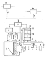
- Switching devices A1 and An are shown in the drawing as subscriber-specific or connection-specific switching devices. They can be occupied on the input side in a manner known per se; if it is a subscriber line circuit, it is permanently connected on the input side to a subscriber station via the relevant subscriber line. Connections are further established on the output side via these switching devices. These processes are known per se and do not require a detailed description here. Also for centrally controlled telephone switching systems, it is known to provide a central part or central interrogators, individually with the aid of the connection-specific and subscriber-individual switching devices are driven in succession, in order to query a g etrlinger Initial switch flag or succession switch flag for a presence of a.
- the individual switching indicators are first fed to the last memory unit f50 and passed on from memory unit to memory unit as in a shift register and finally fed to the memory unit fl. Via an information path fz, the switching indicators mentioned are successively called up from the relevant central control unit or sub-control unit and supplied to a corresponding information processing in a manner known per se. This takes place in the same order as these switching indicators are recorded one after the other by the receiving element B and fed to the FiFo memory FF. These processes are known per se and do not require any further detailed description here.
- the switching indicators arriving via the information path b are differentiated into initial switching indicators and subsequent switching indicators; Of these, only the initial switching indicators are fed to an input device C via the information path c. With each initial switching indicator, this gives a switching pulse via the information paths d and de to a counter E, which is used to determine the information processing traffic load of the central control unit and to identify information processing traffic overloads and to prevent such overloads.
- the counter E has a number of counter elements el to e8, of which one is always marked, which is indicated by the arrow shown. In the switching state shown, the counter el is marked. - The counter E is therefore switched forward with each initial switching indicator. This is done using the information channels d and de.
- the counter E is at regular intervals according to the information processing capacity switched backwards.
- downshift pulses are emitted from a pulse generator G to the counter E via an information path g.
- the pulse frequency of these downshift pulses corresponds to the processing capacity; this is in turn dimensioned according to the sequence of information processing operations by the central control unit.
- the counter E is switched from a zero position to the switching state shown by a first switching pulse arriving via the information path de, in which the switching element el is thus marked. Meeting in the same mean time interval Next Unlock pulses via the Informaticnsweg de one, as well as reverse shift pulses via the information path from the pulse g G, the counter E is equal to fast forward connected as it is also backward tet g eschal-. The counter E keeps its current counter reading on average. If the switching pulses via the information path de follow at shorter intervals than the downshifting pulses which arrive via the information path g, the counter - viewed as a whole - is successively switched forward.
- the counter E is always forwarded by two forward switching pulses, while at the same time it is switched backward by means of only one downshift pulse. The same applies vice versa, if the switching pulses impinge on the counter E with a lower frequency than the reverse switching pulses, the counter E reaches its zero level by receiving reverse switching pulses, so it remains in it until a switching pulse arrives again via the information paths d and de due to an initial switching indicator.
- the counter E If the switching pulses for the counter E follow in a greater density than the reverse switching pulses, the counter E as a whole is switched ever further forward with time. If its counter reading reaches an upper limit value corresponding to counter e7 or an even higher value corresponding to counter e8, this is registered by a registration device e0 and reported to an AND circuit H via an information path ho. This message exists as long and only as long as one of the counter elements e7 or e8 is marked, as long as the counter reading has a value that is assigned to one of these two counter elements.
- the output signal from the registration device e0 is also fed via a signal path bl as a rejection signal to the receiving element B, which, in the manner already described above, manages to reject all further incoming initial switching indicators or a portion thereof, possibly also the initial switching indicator leading to the aforementioned limit value.
- the receiving element B adds a rejection indicator corresponding to the rejection signal to the respective initial switching indicator.
- a memory e is also provided, which receives a marking of one of the counter elements el to e3.
- the memory e records this marking in each case.
- the counter reading corresponding to the counter e3 represents a lower limit value with regard to the information processing traffic load of the central control unit.
- the memory E thus takes up the criterion that the counter reading is at or below this limit value and stores this criterion for a termination of this criterion timed period.
- the counter E is indexed faster than it is indexed becomes, the counter reading of the counter E reaches values which correspond to the counter elements e4, e5 and e6.
- the start of a defined period of time is set at the time of this change.
- the memory e stores the criterion that one of the counting elements el to e3 is or was marked for the duration of this period.
- the counter E outputs the aforementioned criterion to the AND circuit H. If the counter E is now switched on and switched backwards so that - seen as a whole - it reaches a counter reading within the period of time that corresponds to the counter e7, the registration device eo also sends a corresponding signal to the AND circuit H via the information path ho . If the AND circuit H receives a criterion via the two information paths h and ho at the same time, a signal is thus detected which indicates that the counter E has received four further switching pulses within the time period, until it has received reverse switching pulses within this time period. This signal therefore indicates a correspondingly high density of initial switching indicators, which leads to reaching the upper limit value within the stated time period.
- This signal announces an imminent information processing traffic congestion generated by successor switching indicators; because this density of relay pulses due to initial switching indicators within the period of time to reach the upper limit value in the counter makes it apparent that a certain flood of associated subsequent switching indicators will arrive in the receiving element B at a corresponding time interval.
- the memory e and the AND circuit H is an overload notification indicator is formed.
- the overload notification flag mentioned immediately reaches a timer P via the information path hl / x / p and is passed on by the timer P immediately (via pi) and for a period measured by the mean time difference between the initial switching flag and the associated first successive switching flag until the overload notification flag ends maintain.
- this timer therefore immediately passes it on via the information path pi and, if the overload notification indicator arriving via the signal path p is terminated, it continues to maintain it for some time from the time of this termination; this time is guaranteed by the timing element P and corresponds to the mean time difference between the initial switching indicator and the associated first subsequent switching indicator.
- This time difference can, however, also be dimensioned somewhat larger, specifically according to the upper region of a spreading range of this time difference, which of course is different in different connection establishment processes and is within a certain spreading range, for example of 4 seconds.
- the overload notification indicator is passed on via the information path pi. It also reaches the pulse generator G via the information path pg. In this it causes the downshifting pulses which it emits to be transmitted to the counter E with an increased interval of time during the duration of the overload announcement indicator received via the information path pg. With the help of the overload indicator, the reverse switching of the counter E is reduced.
- the overload announcement signal also passes from the timing element P via the information path pi / pd to an acceleration device D and in this means that the forward switching of the counter E is increased on the basis of initial switching indicators.
- the acceleration device D outputs five relay pulses via the information path de to the counter E, for example on the basis of four pulses obtained via the information path d. So that the forward switching of the counter E is increased; in this case the increase factor is 1.25.
- the intensity of the increase which is achieved with the acceleration device D can also be made smaller or larger.
- the overload indicator increases the forward switching of the counter with the aid of the acceleration device D, and at the same time it reduces its reverse switching by influencing the pulse generator G; however, it is equally possible to only increase the forward switching of the counter E or only to decrease its reverse switching.
- the degree of increase or the degree of reduction can be chosen as desired and set in the acceleration device D or in the pulse generator G.
- the criterion pending from the memory e and the signal arising when the upper limit value in the counter E is reached are also linked via the registration device eo to an additional criterion indicating a low current information processing traffic load in order to form the overload announcement indicator .
- the connection of the information paths hl and p is broken at the switching point x and instead the dash-dotted line is shown provided connection to another AND circuit L provided.
- the signal emitted by the AND circuit H via the information path h1 is thus fed to the AND circuit L in this case.
- This also receives a signal from the filling level measuring device F of the FiFo memory FF via the information path f if the FiFo memory is relatively empty.
- the degree of filling measuring device F thus indicates a relatively low degree of filling. You may output an output signal via the information path f to the AND circuit L if a maximum of nine storage units (fl to f9) of the FiFo memory FF have stored switching indicators (initial switching indicators and / or subsequent switching indicators). If, given this further development of the invention, input signals from the AND circuit H on the one hand and from the degree of filling device F on the other hand arrive in the AND circuit L, the AND circuit L thus outputs an output signal to the timing element P.
- the circuit arrangement is thus designed in accordance with this development of the invention, the criterion pending from the memory e and the signal which arises when the upper limit value is reached and is detected by the registration device eo is also relatively low in order to form the overload notification indicator linked additional criterion indicating the current information traffic load of the central control unit, which is output by the degree of filling measuring device F of the FiFo memory FF via the information path f to the AND circuit L.
- the formation of the overload announcement indicator therefore presupposes that the sudden rapid increase in the number of incoming initial switching indicators occurs with the FiFo memory still relatively empty, which is particularly characteristic of the operating situation immediately after an activation, i.e. for the operational start situation.
- the degree of filling measuring device in such a way that it only detects the number of stored successor switching indicators. Under this condition, the filling level measuring device would only issue the additional criterion if only two or three subsequent switching indicators are stored in the FiFo memory FF.
- the additional criterion mentioned which is fed to the AND circuit L via the information path f, instead of the degree of filling measuring device, rather is formed by a further counter, which, however, is not shown in the drawing.
- This counter would additional criterion by counting the g within a measurement period, in particular the period of time arrivals succession switch flag or the initial switching signals and the succession switching signals by comparing the respective counting result with a partial load Limit value win if it falls below or is not exceeded.
- This counter would be constructed similarly to counter E; However, it would not only be given the initial switching indicators, but either the initial switching indicators together with the successor switching indicators or only the successor switching indicators. This counter would thus recognize the operating situation of a relatively low information processing traffic load of the central control unit with a similar effect as the filling degree measuring device.
- the criterion pending from the memory e and the signal arising in the counter E when the upper limit value is reached are also combined with the an additional criterion indicating a small current information processing traffic load is linked, so that even greater security for the detection of the typical start-up situation for the central control unit is achieved.
- This operational start-up situation is characterized by the fact that from the time of switching on, i.e.
- the additional criterion is formed by counting the request signals of the central control unit arriving within a measurement period, in particular the period of time when the FiFo memory is empty.
- the central control unit sends such request signals to the FiFo memory when it is ready for further information processing operations, that is, when it tries to retrieve a further switching identifier from the FiFo memory via the information path fz.
- the central control unit repeats the corresponding request signals at short intervals.
- it is therefore provided to count the request signals which the central control unit emits while the FiFo memory is empty at the same time within a measurement period, in particular the specified time period. The more often the FiFo memory is completely empty, the greater the number of request signals fed to a corresponding counter, which is when the FiFo is empty are delivered by the central control unit.
- the acceleration device D is designed such that it receives a certain number of additional forward switching counting steps of the counter E upon receipt of the overload announcement indicator via the information path pd, to which this counter is caused independently of the initial switching indicators. With the aid of the overload announcement indicator, the forward switching of the counter is increased and / or its reverse switching is reduced, as explained.
- Initial switching indicators arriving during the rejection signal mentioned above are provided with a rejection indicator. This has the effect that any initial switching label provided in this way with a rejection label is not forwarded to the FiFo memory.
- the initial switching indicator also includes data indicating the respective place of origin, i.e. the respective subscriber-specific or connection-specific switching device (A1 to An), the data relating to the respective place of origin ensure that not only the initial switching indicator provided with a rejection indicator but also ach Riversideschaltkenn Rum all the respective initial switching signals individually associated N, where the source address in question is attached to each also are each provided with a rejection indicator. This has the effect that entire series of switching indicators are always rejected, that is to say are not fed to the FiFo memory.
- this deviation solution takes place in the receiving organ B; it is also possible to send a rejection signal to the subscriber-specific or connection-specific switching device which is identified by the data about the place of origin of the initial switching identifier. It can thereby be achieved that, after rejection of an initial switching identifier, the switching identifier associated with it is not even passed on to the receiving element B from the relevant subscriber-specific or connection-specific switching device.
Landscapes
- Engineering & Computer Science (AREA)
- Signal Processing (AREA)
- Computer Networks & Wireless Communication (AREA)
- Monitoring And Testing Of Exchanges (AREA)
- Exchange Systems With Centralized Control (AREA)
Priority Applications (1)
| Application Number | Priority Date | Filing Date | Title |
|---|---|---|---|
| AT85109990T ATE43766T1 (de) | 1984-08-13 | 1985-08-08 | Schaltungsanordnung fuer fernmeldevermittlungsanlagen, insbesondere fernsprechvermittlungsanlagen, mit informationsverarbeitenden schaltwerken und die verkehrsbelastung erkennenden zaehlern. |
Applications Claiming Priority (2)
| Application Number | Priority Date | Filing Date | Title |
|---|---|---|---|
| DE3429775 | 1984-08-13 | ||
| DE3429775 | 1984-08-13 |
Publications (3)
| Publication Number | Publication Date |
|---|---|
| EP0171761A2 true EP0171761A2 (fr) | 1986-02-19 |
| EP0171761A3 EP0171761A3 (en) | 1986-07-16 |
| EP0171761B1 EP0171761B1 (fr) | 1989-05-31 |
Family
ID=6242958
Family Applications (1)
| Application Number | Title | Priority Date | Filing Date |
|---|---|---|---|
| EP85109990A Expired EP0171761B1 (fr) | 1984-08-13 | 1985-08-08 | Montage pour installations de télécommunications, en particulier pour centraux téléphoniques comprenant des processeurs d'informations et des compteurs qui reconnaissent la charge de trafic |
Country Status (3)
| Country | Link |
|---|---|
| EP (1) | EP0171761B1 (fr) |
| AT (1) | ATE43766T1 (fr) |
| DE (1) | DE3570819D1 (fr) |
Cited By (2)
| Publication number | Priority date | Publication date | Assignee | Title |
|---|---|---|---|---|
| WO1997029610A1 (fr) * | 1996-02-06 | 1997-08-14 | Nokia Telecommunications Oy | Procede et dispositif permettant de limiter la charge de teleappels sur un systeme de communication mobile |
| WO1998052338A1 (fr) * | 1997-05-13 | 1998-11-19 | Siemens Aktiengesellschaft | Regulation de charge dans un dispositif de communication |
Family Cites Families (4)
| Publication number | Priority date | Publication date | Assignee | Title |
|---|---|---|---|---|
| DE2731829C3 (de) * | 1977-07-14 | 1980-09-18 | Standard Elektrik Lorenz Ag, 7000 Stuttgart | Zentralgesteuerte Fernmeldevermittlungs anlage |
| ES462307A1 (es) * | 1977-09-13 | 1978-05-16 | Standard Electrica Sa | Un procedimiento de control dinamico de sobrecarga en cen- trales telefonicas gobernadas por ordenador. |
| NL8202419A (nl) * | 1982-06-15 | 1984-01-02 | Philips Nv | Werkwijze voor het voorkomen van overbelasting van de centrale besturing van een telecommunicatiesysteem en inrichting voor het uitvoeren van de werkwijze. |
| DE3311875A1 (de) * | 1983-03-31 | 1984-10-04 | Siemens AG, 1000 Berlin und 8000 München | Schaltungsanordnung fuer fernmeldeanlagen, insbesondere fernsprechvermittlungsanlagen, mit informationsverarbeitenden schaltwerken und einrichtungen zur abwehr von ueberbelastungen |
-
1985
- 1985-08-08 DE DE8585109990T patent/DE3570819D1/de not_active Expired
- 1985-08-08 EP EP85109990A patent/EP0171761B1/fr not_active Expired
- 1985-08-08 AT AT85109990T patent/ATE43766T1/de not_active IP Right Cessation
Cited By (4)
| Publication number | Priority date | Publication date | Assignee | Title |
|---|---|---|---|---|
| WO1997029610A1 (fr) * | 1996-02-06 | 1997-08-14 | Nokia Telecommunications Oy | Procede et dispositif permettant de limiter la charge de teleappels sur un systeme de communication mobile |
| AU715948B2 (en) * | 1996-02-06 | 2000-02-10 | Nokia Telecommunications Oy | Method and arrangement for limiting paging load in a mobile communication system |
| CN1097415C (zh) * | 1996-02-06 | 2002-12-25 | 诺基亚电信公司 | 限制移动通信系统中寻呼负载的方法和设备 |
| WO1998052338A1 (fr) * | 1997-05-13 | 1998-11-19 | Siemens Aktiengesellschaft | Regulation de charge dans un dispositif de communication |
Also Published As
| Publication number | Publication date |
|---|---|
| EP0171761A3 (en) | 1986-07-16 |
| EP0171761B1 (fr) | 1989-05-31 |
| ATE43766T1 (de) | 1989-06-15 |
| DE3570819D1 (en) | 1989-07-06 |
Similar Documents
| Publication | Publication Date | Title |
|---|---|---|
| DE68907967T3 (de) | Anrufverkehrssteuerung. | |
| EP0419958A2 (fr) | Circuit dans un central de commutation à multiplexage temporel asynchrone pour détecter la quantité de données transmises et pour contrôler la conformité avec des taux de bits specifiés | |
| EP0121239B1 (fr) | Montage pour installations de télécommunication, en particulier pour centraux téléphoniques comprenant des processeurs d'informations et des dispositifs pour éviter des surcharges | |
| EP0419959A2 (fr) | Circuit pour contrôler le respet de débits préétablis lors de la transmission de cellules de données | |
| EP0121236A2 (fr) | Montage pour installations de télécommunication, en particulier pour centraux téléphoniques comprenant des processeurs d'informations et des dispositifs pour éviter des surcharges | |
| EP0121865B1 (fr) | Montage pour installations de télécommunication, en particulier pour centraux téléphoniques comprenant des processeurs d'informations et des dispositifs pour éviter des surcharges | |
| DE2208396B2 (de) | Zeitmultiplex-Nachrichtenvermittlungssystem, insbesondere für PCM | |
| EP0121238B1 (fr) | Montage pour installations de télécommunication, en particulier pour centraux téléphoniques comprenant des processeurs d'informations et des dispositifs pour éviter des surcharges | |
| EP0169551B1 (fr) | Montage pour centraux de télécommunication, en particulier pour centraux téléphoniques avec des dispositifs de traitement d'informations et des dispositifs de mesure de trafic | |
| EP0121237A2 (fr) | Montage pour installations de télécommunication, en particulier pour centraux téléphoniques comprenant des processeurs d'informations et des dispositifs pour éviter des surcharges | |
| EP0171761B1 (fr) | Montage pour installations de télécommunications, en particulier pour centraux téléphoniques comprenant des processeurs d'informations et des compteurs qui reconnaissent la charge de trafic | |
| EP0134010B1 (fr) | Circuit pour installations de télécommunications, en particulier centraux téléphoniques avec des circuits de traitement d'informations de contrôle centralisés et/ou partiellement centralisés | |
| DE3328575C2 (fr) | ||
| DE3328574C2 (de) | Schaltungsanordnung für Fernmeldeanlagen, insbesondere Fernsprechvermittlungsanlagen | |
| DE3429793C2 (fr) | ||
| EP0134009B1 (fr) | Circuit pour installations de télécommunications en particulier centraux téléphoniques avec des circuits de traitement d'informations de contrôle | |
| EP0213382B1 (fr) | Montage pour centraux de télécommunications, en particulier pour centraux téléphoniques équipés de processeurs de contrôle et de dispositifs de mesure de trafic | |
| EP0213408B1 (fr) | Montage pour centraux de télécommunications, en particulier pour centraux téléphoniques équipés de processeurs de contrôle et de dispositifs de mesure de trafic | |
| EP0166101B1 (fr) | Montage pour centraux de télécommunication, en particulier des centraux téléphoniques avec des appareils de traitement d'informations et des dispositifs de mesure du traffic | |
| EP0171784B1 (fr) | Circuit pour installations de télécommunications, en particulier centraux téléphoniques avec des circuits de traitement d'informations de contrôle centralisés et/ou décentralisés | |
| EP0177735B1 (fr) | Montage pour installations de télécommunication, en particulier pour centraux téléphoniques comprenant des dispositifs de traitement d'informations centralisés et/ou décentralisés | |
| EP0291815B1 (fr) | Procédé pour régler la charge de traffic en fonction du nombre de tentatives d'appel dans un central de télécommunication | |
| DE956594C (de) | Schaltungsanordnung fuer Speichereinrichtungen in Fernmelde-, insbesondere Fernsprechanlagen | |
| DE3736897C2 (fr) | ||
| DE3435497A1 (de) | Schaltungsanordnung fuer fernmeldevermittlungsanlagen, insbesondere fernsprechvermittlungsanlagen mit informationsverarbeitenden zentralen und/oder dezentralen schaltwerken |
Legal Events
| Date | Code | Title | Description |
|---|---|---|---|
| PUAI | Public reference made under article 153(3) epc to a published international application that has entered the european phase |
Free format text: ORIGINAL CODE: 0009012 |
|
| AK | Designated contracting states |
Designated state(s): AT BE CH DE FR GB IT LI NL SE |
|
| PUAL | Search report despatched |
Free format text: ORIGINAL CODE: 0009013 |
|
| AK | Designated contracting states |
Kind code of ref document: A3 Designated state(s): AT BE CH DE FR GB IT LI NL SE |
|
| 17P | Request for examination filed |
Effective date: 19870114 |
|
| 17Q | First examination report despatched |
Effective date: 19880728 |
|
| GRAA | (expected) grant |
Free format text: ORIGINAL CODE: 0009210 |
|
| AK | Designated contracting states |
Kind code of ref document: B1 Designated state(s): AT BE CH DE FR GB IT LI NL SE |
|
| REF | Corresponds to: |
Ref document number: 43766 Country of ref document: AT Date of ref document: 19890615 Kind code of ref document: T |
|
| REF | Corresponds to: |
Ref document number: 3570819 Country of ref document: DE Date of ref document: 19890706 |
|
| ET | Fr: translation filed | ||
| ITF | It: translation for a ep patent filed | ||
| GBT | Gb: translation of ep patent filed (gb section 77(6)(a)/1977) | ||
| PLBE | No opposition filed within time limit |
Free format text: ORIGINAL CODE: 0009261 |
|
| STAA | Information on the status of an ep patent application or granted ep patent |
Free format text: STATUS: NO OPPOSITION FILED WITHIN TIME LIMIT |
|
| 26N | No opposition filed | ||
| ITTA | It: last paid annual fee | ||
| PGFP | Annual fee paid to national office [announced via postgrant information from national office to epo] |
Ref country code: GB Payment date: 19940718 Year of fee payment: 10 |
|
| PGFP | Annual fee paid to national office [announced via postgrant information from national office to epo] |
Ref country code: AT Payment date: 19940729 Year of fee payment: 10 |
|
| PGFP | Annual fee paid to national office [announced via postgrant information from national office to epo] |
Ref country code: BE Payment date: 19940818 Year of fee payment: 10 |
|
| PGFP | Annual fee paid to national office [announced via postgrant information from national office to epo] |
Ref country code: FR Payment date: 19940824 Year of fee payment: 10 |
|
| PGFP | Annual fee paid to national office [announced via postgrant information from national office to epo] |
Ref country code: SE Payment date: 19940829 Year of fee payment: 10 |
|
| PGFP | Annual fee paid to national office [announced via postgrant information from national office to epo] |
Ref country code: NL Payment date: 19940831 Year of fee payment: 10 |
|
| PGFP | Annual fee paid to national office [announced via postgrant information from national office to epo] |
Ref country code: CH Payment date: 19941207 Year of fee payment: 10 |
|
| EAL | Se: european patent in force in sweden |
Ref document number: 85109990.3 |
|
| PG25 | Lapsed in a contracting state [announced via postgrant information from national office to epo] |
Ref country code: GB Effective date: 19950808 Ref country code: AT Effective date: 19950808 |
|
| PG25 | Lapsed in a contracting state [announced via postgrant information from national office to epo] |
Ref country code: SE Effective date: 19950809 |
|
| PG25 | Lapsed in a contracting state [announced via postgrant information from national office to epo] |
Ref country code: LI Effective date: 19950831 Ref country code: CH Effective date: 19950831 Ref country code: BE Effective date: 19950831 |
|
| BERE | Be: lapsed |
Owner name: SIEMENS A.G. BERLIN UND MUNCHEN Effective date: 19950831 |
|
| PG25 | Lapsed in a contracting state [announced via postgrant information from national office to epo] |
Ref country code: NL Effective date: 19960301 |
|
| GBPC | Gb: european patent ceased through non-payment of renewal fee |
Effective date: 19950808 |
|
| REG | Reference to a national code |
Ref country code: CH Ref legal event code: PL |
|
| PG25 | Lapsed in a contracting state [announced via postgrant information from national office to epo] |
Ref country code: FR Effective date: 19960430 |
|
| NLV4 | Nl: lapsed or anulled due to non-payment of the annual fee |
Effective date: 19960301 |
|
| EUG | Se: european patent has lapsed |
Ref document number: 85109990.3 |
|
| REG | Reference to a national code |
Ref country code: FR Ref legal event code: ST |
|
| PGFP | Annual fee paid to national office [announced via postgrant information from national office to epo] |
Ref country code: DE Payment date: 19971022 Year of fee payment: 13 |
|
| PG25 | Lapsed in a contracting state [announced via postgrant information from national office to epo] |
Ref country code: DE Free format text: LAPSE BECAUSE OF NON-PAYMENT OF DUE FEES Effective date: 19990601 |