EP0171820A2 - Appareil et méthode pour la détection ultrasonore d'inclusions dans des métaux fondus - Google Patents
Appareil et méthode pour la détection ultrasonore d'inclusions dans des métaux fondus Download PDFInfo
- Publication number
- EP0171820A2 EP0171820A2 EP85110456A EP85110456A EP0171820A2 EP 0171820 A2 EP0171820 A2 EP 0171820A2 EP 85110456 A EP85110456 A EP 85110456A EP 85110456 A EP85110456 A EP 85110456A EP 0171820 A2 EP0171820 A2 EP 0171820A2
- Authority
- EP
- European Patent Office
- Prior art keywords
- transducer
- coupling medium
- ultrasonic waves
- surface portion
- window
- Prior art date
- Legal status (The legal status is an assumption and is not a legal conclusion. Google has not performed a legal analysis and makes no representation as to the accuracy of the status listed.)
- Withdrawn
Links
Images

Classifications
-
- G—PHYSICS
- G01—MEASURING; TESTING
- G01N—INVESTIGATING OR ANALYSING MATERIALS BY DETERMINING THEIR CHEMICAL OR PHYSICAL PROPERTIES
- G01N29/00—Investigating or analysing materials by the use of ultrasonic, sonic or infrasonic waves; Visualisation of the interior of objects by transmitting ultrasonic or sonic waves through the object
- G01N29/22—Details, e.g. general constructional or apparatus details
- G01N29/24—Probes
- G01N29/2437—Piezoelectric probes
-
- G—PHYSICS
- G01—MEASURING; TESTING
- G01N—INVESTIGATING OR ANALYSING MATERIALS BY DETERMINING THEIR CHEMICAL OR PHYSICAL PROPERTIES
- G01N29/00—Investigating or analysing materials by the use of ultrasonic, sonic or infrasonic waves; Visualisation of the interior of objects by transmitting ultrasonic or sonic waves through the object
- G01N29/22—Details, e.g. general constructional or apparatus details
- G01N29/228—Details, e.g. general constructional or apparatus details related to high temperature conditions
-
- G—PHYSICS
- G01—MEASURING; TESTING
- G01N—INVESTIGATING OR ANALYSING MATERIALS BY DETERMINING THEIR CHEMICAL OR PHYSICAL PROPERTIES
- G01N29/00—Investigating or analysing materials by the use of ultrasonic, sonic or infrasonic waves; Visualisation of the interior of objects by transmitting ultrasonic or sonic waves through the object
- G01N29/22—Details, e.g. general constructional or apparatus details
- G01N29/24—Probes
- G01N29/2462—Probes with waveguides, e.g. SAW devices
-
- G—PHYSICS
- G01—MEASURING; TESTING
- G01N—INVESTIGATING OR ANALYSING MATERIALS BY DETERMINING THEIR CHEMICAL OR PHYSICAL PROPERTIES
- G01N2291/00—Indexing codes associated with group G01N29/00
- G01N2291/02—Indexing codes associated with the analysed material
- G01N2291/025—Change of phase or condition
- G01N2291/0252—Melting, molten solids
Definitions
- the present invention relates to apparatus and methods for ultrasonic detection of inclusions in molten metals.
- the devices relying upon a probe of titanium metal have a short operating life when used to detect inclusions in molten aluminum because titanium is soluble in aluminum.
- solid titanium and other solid metal probes usually contain grain boundaries, gas voids, inclusions and other impurities which may attenuate ultrasonic waves.
- a further limitation of prior art devices is the need to focus on a reflecting surface. Under production conditions, it is difficult to focus an ultrasonic beam and to maintain a reflective surface at a constant distance from the beam.
- One advantage of the probe described herein is that it is suitable for detecting particles in molten aluminum having a smaller effective particle size than with prior art devices.
- Another advantage is that the apparatus and method described herein are suitable for use either with or without focusing a beam of ultrasonic waves. In addition, it is not necessary to have a reflecting surface.
- a further advantage of a preferred probe of the invention is that it includes an amorphous silica window that is wetted by molten aluminum.
- an apparatus for carrying ultrasonic waves between a transducer and a body comprising a molten metal or alloy.
- the apparatus includes a probe.comprising an inert refractory shell, a window supported by the shell for carrying ultrasonic waves between a coupling medium and the body and a coupling medium contained within the shell for carrying ultrasonic waves between a transducer and the window.
- the window comprises an interior surface portion contacting the coupling medium and an exterior surface portion that is wettable by the molten body.
- the acoustic attenuation factors for ultrasonic waves between the transducer and coupling medium, between the coupling medium and interior surface portion, between the interior and exterior surface portions, and between the exterior surface portion and the body are each less than about 3 dB. These attenuation factors are each preferably lesor than about 2 dB, more preferably less than about 1 dB and optimally as small as possible.
- the window preferably comprise amorphous silica.
- the coupling medium comprises liquid gallium.
- the coupling medium preferably comprises a minor proportion of a metal solute dissolved in the gallium that reduces differences in acoustic impedance between the coupling medium, transducer and interior surface portion of the window.
- the coupling medium comprises about 4.8 wtl silver dissolved in liquid gallium and the window is amorphous silica
- the acoustic impedance of the coupling medium is approximately equal to the acoustic impedance of the interior surface portion and approximately equal to the acoustic impedance of the transducer.
- the liquid gallium is preferably treated to remove oxides, solid inclusions and dissolved gases. Such treatment is desirable in order to minimize reflection of acoustic waves within the coupling medium.
- a probe containing liquid gallium has the advantage of lacking grain boundaries, gas voids, inclusions and other impurities found in solid metal probes.
- a preferred apparatus includes a piezoelectric transducer capable of generating ultrasonic waves having a frequency of about 8-25 MHz. In order to maintain effective operation of the transducer it is spaced from the window, preferably by a distance of at least 10 cm.
- the preferred apparatus further comprises a cooling means for maintaining the transducer and liquid gallium adjacent thereto at a temperature below about 149°C.
- a probe having an inert refractory shell is capable of withstanding the caustic effects of molten aluminum and is sufficiently resistant to thermal stress for use with molten aluminum.
- the probe 10 shown in Figure 1 is used for detecting particulate inclusions in a body 12 comprising a molten metal or alloy. While the particular apparatus and method described herein are intended for detection of particulate inclusions in molten aluminum and aluminum alloys, the invention is not limited to use solely with aluminum or for detection of only particulate inclusions.
- the present apparatus and method are also probably suitable for ultrasonic testing of other metals and alloys having melting points below about 1,000°C, including but not limited to bismuth, gallium, indium, lead, lithium, magnesium, mercury, potassium, sodium, tin, zinc and their alloys. With appropriate modifications, the invention may also be applicable to ultrasonic testing of higher melting metals such as cobalt, copper, gold, iron, manganese, nickel, silver and their alloys.
- the probe 10 comprises a hollow tubular refractory shell or envelope 14 containing a liquid metal coupling medium 16.
- the shell 14 is provided with an upwardly extending riser tube 18 in order to allow for expansion and contraction of the coupling medium 16 at different temperatures.
- the shell 14 must be chemically inert both to the body 12 and coupling medium 16 at elevated temperatures.
- a preferred shell 14 is made from a predominantly alumina refractory material. This material is inert to aluminum alloys in the body 12 and to liquid gallium in the coupling medium 16 at elevated temperatures up to at least 800°C.
- the shell 14 may also be made from other inert refractories such as silica, silicon carbide and mullite.
- a piezoelectric transducer 20 adjacent an upper end of the probe 10 sends ultrasonic waves through the coupling medium 16 to a window 22 spaced downwardly of the transducer 20.
- the preferred transducer 20 shown is a piezoelectric transducer. This transducer generates ultrasonic waves having a frequency of about 8-25 MHz in response to electrical stimuli. A particularly preferred operating frequency is about 15 MHz.
- the transducer 20 is situated adjacent an amorphous silica upper wall or upper window 23 of the shell 14.
- the transducer 20 is fastened to the upper wall 23 by means of a high temperature adhesive.
- the probe 10 is provided with a cooling means or cooling jacket 24 for maintaining the transducer 20 and adjacent coupling medium 16 at a temperature at below about 149°C.
- the preferred probe 10 utilizes water as a coolant in the cooling means 24.
- the cooling means may be omitted entirely from the probe 10 if the apparatus. is used for detection of inclusions in metals having low melting points such as bismuth, lithium or their alloys, or if a sufficiently large distance is maintained between the window and transducer 20 to insulate the transducer 20 from the generally hotter body 12.
- the transducer 20 and window 24 should be separated by a distance of at least 10 cm. While it is desirable to maintain this distance as small as possible consistent with an acceptable thermal gradient, the distance must be increased in certain cases to avoid damaging the transducer 20. In the particularly preferred probe 10 described herein, the transducer 20 and window 22 are separated by a distance of about 15 cm.
- the window 22 includes an interior surface portion 22a contacting the coupling medium 16 and an exterior surface portion 22b that is wettable by the body 12. It is contemplated that the interior surface portion 22a and exterior surface portion 22b will generally comprise a unitary structure, although composite structures are also within the scope of the invention. A unitary structure is preferred in order to minimize acoustic attenuation between the interior surface portion 22a and exterior surface portion 22b.
- a particularly preferred window 22 is made from amorphous silica and has a cylindrical or disc shape.
- Silica has the advantage of being readily wetted by molten aluminum and its alloys.
- the coupling medium 16 and window 22 are each made from materials which are selected to reduce acoustic attenuation between the transducer 20 and coupling medium 16, between the coupling medium 16 and window 22, and between the window 22 and body 12.
- acoustic attenuation factor is defined by the following expression: wherein B is the acoustic intensity level in decibels and I is acoustic intensity of the sound waves, expressed in W/m 2 .
- the acoustic attenuation factors for ultrasonic waves between the transducer 20 and coupling medium 16, between the coupling medium 16 and window 22, and between the window 22 and body 12 should each be less than about 1 dB.
- a minor proportion of a metal solute is dissolved in liquid gallium.
- the coupling medium 16 preferably comprises about 2.5-5 wtX silver dissolved in liquid gallium.
- the concentration of dissolved silver in the coupling medium 16 should generally be maintained below about 5 wt% in order to avoid precipitation of phases that might interfere with transmission of sound waves.
- the gallium should be treated to remove oxides, solid inclusions and dissolved gases so that sound waves will be transmitted efficiently between transducer 20 and window 22.
- the preferred coupling medium containing about 4.8 wt2 silver dissolved in gallium has an acoustic impedance that is approximately equal to the acoustic impedance of the window and approximately equal to the acoustic impedance of the transducer 20. Accordingly, acoustic attenuation at interfaces between the transducer 20 and coupling medium 16 and between the coupling medium 16 and interior surface portion 22a is essentially zero.
- the window 22 is made from amorphous silica
- acoustic attenuation between the outer surface portion 22b and a body 12 of molten aluminum is calculated to be less than 1 dB. Accordingly, the probe of the invention is highly efficient for carrying ultrasonic waves between the transducer 20 and body 12 without thermal damage to the transducer 20.
- the coupling medium 16 preferably has a low vapor pressure at the temperature of the body 12. Liquids having significant vapor pressure at elevated temperatures may form bubbles that would interfere with transmission of ultrasonic wave trains through the coupling medium.
- An advantage of liquid gallium is that its boiling point is 2403°C. Accordingly, a coupling medium comprising a principal proportion of liquid gallium has low vapor pressure even at temperatures up to about 732°C (135 ⁇ °F), the highest temperature at which aluminum alloys are usually maintained.
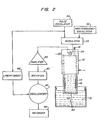
- the apparatus further comprises a voltage pulse oscillator 30, a high frequency oscillator 32 generating alternating voltage of ultrasonic frequency, and a modulator 34 receiving electrical pulses from the voltage pulse oscillator 30 and a high frequency oscillator 32.
- the modulator 34 generates a direct current voltage train having a voltage of about 300 volts by passing voltage of ultrasonic frequency only during the period that the modulator 34 is receiving a pulse from the voltage pulse oscillator 30. This direct current voltage train energizes the transducer 20.
- the transducer 20 also acts as a receiving transducer for receiving wave trains from the body 12 through the window 22 and coupling medium 16:
- the receiving transducer 20 then generates voltage trains in response to wave trains received from the body 12.
- the voltage trains so generated are sent to an amplifier 40, rectifier 42 and oscilloscope 44.
- a linear sweep circuit 46 synchronized with the voltage pulse oscillator 30 is connected to the oscilloscope 44.
- the oscilloscope 44 has a spot that is deflected in one direction by the sweep circuit 46 and deflected in a different direction by the voltage output from the receiving transducer 20.
- a permanent record of the oscilloscope display is maintained in a recorder 50.
- the voltage pulse oscillator 30, high frequency oscillator 32 and modulator 34 are referred to collectively as a "pulser".
- the amplifier 40, rectifier 42, oscilloscope 44 and sweep circuit 46 are similarly called "receiver".
- ultrasonic waves generated by the transducer 20 are transmitted through the coupling medium 16 and window 22 into a body 12 of molten aluminum.
- extra vibration wave trains are sent back to the transducer 20 and voltage trains are generated in response to such ultrasonic wave trains.
- the voltage trains are then displayed on the oscilloscope 44.
- An advantage of the probe 10 described herein is that it is so efficient at transmitting ultrasonic wave trains that the claimed apparatus detects smaller particles 60 than prior art apparatus.
- the probe 10 consistently detects solid particulate inclusions having an effective diameter of less than about 400 microns, and particles as small as about 50 microns have been detected in molten aluminum.
- the probe 10 is theoretically capable of detecting particles in about the 1-10 micron diameter range.
Landscapes
- Physics & Mathematics (AREA)
- Health & Medical Sciences (AREA)
- Life Sciences & Earth Sciences (AREA)
- Chemical & Material Sciences (AREA)
- Analytical Chemistry (AREA)
- Biochemistry (AREA)
- General Health & Medical Sciences (AREA)
- General Physics & Mathematics (AREA)
- Immunology (AREA)
- Pathology (AREA)
- Investigating Or Analyzing Materials By The Use Of Ultrasonic Waves (AREA)
Applications Claiming Priority (2)
| Application Number | Priority Date | Filing Date | Title |
|---|---|---|---|
| US642488 | 1984-08-20 | ||
| US06/642,488 US4563895A (en) | 1984-08-20 | 1984-08-20 | Apparatus and method for ultrasonic detection of inclusions in molten metals |
Publications (1)
| Publication Number | Publication Date |
|---|---|
| EP0171820A2 true EP0171820A2 (fr) | 1986-02-19 |
Family
ID=24576776
Family Applications (1)
| Application Number | Title | Priority Date | Filing Date |
|---|---|---|---|
| EP85110456A Withdrawn EP0171820A2 (fr) | 1984-08-20 | 1985-08-20 | Appareil et méthode pour la détection ultrasonore d'inclusions dans des métaux fondus |
Country Status (6)
| Country | Link |
|---|---|
| US (1) | US4563895A (fr) |
| EP (1) | EP0171820A2 (fr) |
| JP (1) | JPS6157851A (fr) |
| AU (1) | AU4382885A (fr) |
| BR (1) | BR8503974A (fr) |
| NO (1) | NO164803C (fr) |
Cited By (2)
| Publication number | Priority date | Publication date | Assignee | Title |
|---|---|---|---|---|
| EP0230880A1 (fr) * | 1986-01-13 | 1987-08-05 | Aluminum Company Of America | Dispositif et procédé pour la détection ultrasonique d'inclusions dans un corps fondu |
| GB2257786A (en) * | 1991-07-13 | 1993-01-20 | British Steel Plc | Liquid steel impurity detector |
Families Citing this family (14)
| Publication number | Priority date | Publication date | Assignee | Title |
|---|---|---|---|---|
| HU194830B (en) * | 1984-10-05 | 1988-03-28 | Richter Gedeon Vegyeszet | Process for the production of derivatives of piridine |
| JPS6342461A (ja) * | 1986-08-07 | 1988-02-23 | Mazda Motor Corp | 燃料成分検出装置 |
| JPH02129850U (fr) * | 1989-03-31 | 1990-10-25 | ||
| US5289436A (en) * | 1992-10-22 | 1994-02-22 | General Electric Company | Ultrasonic waveguide |
| US5633462A (en) * | 1994-07-19 | 1997-05-27 | Apa Systems | Method and apparatus for detecting the condition of the flow of liquid metal in and from a teeming vessel |
| US6539805B2 (en) | 1994-07-19 | 2003-04-01 | Vesuvius Crucible Company | Liquid metal flow condition detection |
| GB9524949D0 (en) * | 1995-12-06 | 1996-02-07 | Kodak Ltd | Bubble detector |
| GB9708451D0 (en) * | 1997-04-26 | 1997-06-18 | British Nuclear Fuels Plc | An acoustic apparatus |
| US6693443B2 (en) | 1999-04-02 | 2004-02-17 | Worcester Polytechnic Institute | Systems for detecting and measuring inclusions |
| FR2796155B1 (fr) | 1999-07-09 | 2001-09-07 | Pechiney Rhenalu | Procede et dispositif ameliores de comptage des inclusions dans un bain de metal liquide par ultrasons |
| CN101793870A (zh) * | 2010-02-10 | 2010-08-04 | 莱芜钢铁股份有限公司 | 一种钢水中夹杂物在线分析装置及方法 |
| CN106796201B (zh) * | 2014-10-07 | 2020-08-07 | 伊苏瓦尔肯联铝业 | 通过超声波检测液态金属的方法 |
| CN105675730B (zh) * | 2016-03-16 | 2019-04-05 | 平高集团有限公司 | 一种灭弧喷口专用超声波检测设备及灭弧喷口检测方法 |
| CN113686953B (zh) * | 2021-09-09 | 2024-09-27 | 哈尔滨工程大学 | 基于超声波能量损失法的水雾湿度测量系统 |
Family Cites Families (6)
| Publication number | Priority date | Publication date | Assignee | Title |
|---|---|---|---|---|
| GB1057802A (en) * | 1962-08-13 | 1967-02-08 | Yawata Iron & Steel Company | Ultrasonic internal flaw detecting apparatus for hot metal |
| GB1127231A (en) * | 1965-01-06 | 1968-09-18 | British Aluminium Co Ltd | Improvements in or relating to methods of and apparatus for testing molten metal |
| US3497728A (en) * | 1967-03-20 | 1970-02-24 | Standard Oil Co | Ultrasonic inspection apparatus |
| US4287755A (en) * | 1979-09-12 | 1981-09-08 | Reynolds Metals Company | Probes for the ultrasonic treatment or inspection of molten aluminum |
| US4261197A (en) * | 1979-09-12 | 1981-04-14 | Reynolds Metals Company | Probe for the ultrasonic inspection of molten aluminum |
| US4509360A (en) * | 1983-06-24 | 1985-04-09 | Massachusetts Institute Of Technology | On-line measurement of fluid mixtures |
-
1984
- 1984-08-20 US US06/642,488 patent/US4563895A/en not_active Expired - Lifetime
-
1985
- 1985-06-19 AU AU43828/85A patent/AU4382885A/en not_active Abandoned
- 1985-08-13 JP JP60177046A patent/JPS6157851A/ja active Pending
- 1985-08-19 NO NO853259A patent/NO164803C/no unknown
- 1985-08-20 BR BR8503974A patent/BR8503974A/pt not_active IP Right Cessation
- 1985-08-20 EP EP85110456A patent/EP0171820A2/fr not_active Withdrawn
Cited By (2)
| Publication number | Priority date | Publication date | Assignee | Title |
|---|---|---|---|---|
| EP0230880A1 (fr) * | 1986-01-13 | 1987-08-05 | Aluminum Company Of America | Dispositif et procédé pour la détection ultrasonique d'inclusions dans un corps fondu |
| GB2257786A (en) * | 1991-07-13 | 1993-01-20 | British Steel Plc | Liquid steel impurity detector |
Also Published As
| Publication number | Publication date |
|---|---|
| NO164803B (no) | 1990-08-06 |
| JPS6157851A (ja) | 1986-03-24 |
| AU4382885A (en) | 1986-02-27 |
| BR8503974A (pt) | 1986-06-03 |
| NO853259L (no) | 1986-02-21 |
| NO164803C (no) | 1990-11-14 |
| US4563895A (en) | 1986-01-14 |
Similar Documents
| Publication | Publication Date | Title |
|---|---|---|
| US4662215A (en) | Apparatus and method for ultrasonic detection of inclusions in a molten body | |
| US4563895A (en) | Apparatus and method for ultrasonic detection of inclusions in molten metals | |
| US4770699A (en) | Method of treating liquid melts | |
| US5604301A (en) | Ultrasound detection techniques | |
| US5708209A (en) | Apparatus and method for ultrasonic particle detection in molten metal | |
| US2697936A (en) | Supersonic testing of hot articles | |
| US4619143A (en) | Apparatus and method for the non-destructive inspection of solid bodies | |
| CN106796201A (zh) | 通过超声波检测液态金属的方法 | |
| JPS6411141B2 (fr) | ||
| US5406849A (en) | Method and apparatus for detecting guided leaky waves in acoustic microscopy | |
| US4995260A (en) | Nondestructive material characterization | |
| JPS5823918B2 (ja) | 欠陥のある核燃料要素を突とめる為の方法 | |
| JPH07280775A (ja) | 超音波を用いた柱上変圧器及び柱上開閉器の浸水検出方法及び装置 | |
| JP2009243931A (ja) | 超音波導波棒および超音波プローブ並びにそれを用いた不純物検出方法および界面位置計測方法 | |
| Ono et al. | Development of ultrasonic techniques with buffer rod in molten aluminum | |
| Hauser | Ultra adhesives for ultrasonic bonding | |
| Currie et al. | Development of an ultrasonic liquid steel inclusion monitor | |
| Könönen et al. | Testing of metal-ceramic joint using scanning acoustic microscopy | |
| GB2257786A (en) | Liquid steel impurity detector | |
| Ghorbanpoor et al. | Laboratory acoustic emission investigation of full size ASTM A-588 bridge beams | |
| JP2001272382A (ja) | 超音波検査方法とこれに使用する装置 | |
| Ihara et al. | High resolution measurements in liquid metal by focused ultrasonic wave | |
| JPH08194050A (ja) | 導波棒を用いた超音波距離計測装置 | |
| Kwun et al. | Feasibility of inclusion detection and characterization in titanium powder compacts using ultrasonics | |
| HOUSE et al. | AUTO |
Legal Events
| Date | Code | Title | Description |
|---|---|---|---|
| PUAI | Public reference made under article 153(3) epc to a published international application that has entered the european phase |
Free format text: ORIGINAL CODE: 0009012 |
|
| AK | Designated contracting states |
Designated state(s): CH DE FR GB LI NL |
|
| STAA | Information on the status of an ep patent application or granted ep patent |
Free format text: STATUS: THE APPLICATION HAS BEEN WITHDRAWN |
|
| 18W | Application withdrawn |
Withdrawal date: 19861002 |
|
| RIN1 | Information on inventor provided before grant (corrected) |
Inventor name: ECKERT, CHARLES EDWARD |