EP0171927A2 - Appareil de surveillance pour patient - Google Patents
Appareil de surveillance pour patient Download PDFInfo
- Publication number
- EP0171927A2 EP0171927A2 EP85305000A EP85305000A EP0171927A2 EP 0171927 A2 EP0171927 A2 EP 0171927A2 EP 85305000 A EP85305000 A EP 85305000A EP 85305000 A EP85305000 A EP 85305000A EP 0171927 A2 EP0171927 A2 EP 0171927A2
- Authority
- EP
- European Patent Office
- Prior art keywords
- data
- patient monitor
- summary data
- output
- measured value
- Prior art date
- Legal status (The legal status is an assumption and is not a legal conclusion. Google has not performed a legal analysis and makes no representation as to the accuracy of the status listed.)
- Withdrawn
Links
Images
Classifications
-
- A—HUMAN NECESSITIES
- A61—MEDICAL OR VETERINARY SCIENCE; HYGIENE
- A61B—DIAGNOSIS; SURGERY; IDENTIFICATION
- A61B5/00—Measuring for diagnostic purposes; Identification of persons
-
- A—HUMAN NECESSITIES
- A61—MEDICAL OR VETERINARY SCIENCE; HYGIENE
- A61B—DIAGNOSIS; SURGERY; IDENTIFICATION
- A61B5/00—Measuring for diagnostic purposes; Identification of persons
- A61B5/145—Measuring characteristics of blood in vivo, e.g. gas concentration or pH-value ; Measuring characteristics of body fluids or tissues, e.g. interstitial fluid or cerebral tissue
-
- A—HUMAN NECESSITIES
- A61—MEDICAL OR VETERINARY SCIENCE; HYGIENE
- A61B—DIAGNOSIS; SURGERY; IDENTIFICATION
- A61B5/00—Measuring for diagnostic purposes; Identification of persons
- A61B5/02—Detecting, measuring or recording for evaluating the cardiovascular system, e.g. pulse, heart rate, blood pressure or blood flow
-
- A—HUMAN NECESSITIES
- A61—MEDICAL OR VETERINARY SCIENCE; HYGIENE
- A61B—DIAGNOSIS; SURGERY; IDENTIFICATION
- A61B5/00—Measuring for diagnostic purposes; Identification of persons
- A61B5/02—Detecting, measuring or recording for evaluating the cardiovascular system, e.g. pulse, heart rate, blood pressure or blood flow
- A61B5/021—Measuring pressure in heart or blood vessels
Definitions
- This invention relates to medical appliances and more particularly, to patient monitors which can convert information on the state of a living body from human patients such as electrocardiogram, heart rate or blood C0 2/ oxygen tension into electrical signals, store the electrical signals, process the electrical signals if necessary, edit the electrical signals and output them as summary data.
- Prior art devices for measuring living body information on the condition of patients which are being observed by continuous monitoring of such faction as electrocardiogram, blood pressure or the like are designed instantly to output the measured values of such information and record the measured values on a recording paper or display them on a CRT (Cathode Ray Tube). A physician then examines the recorded or displayed values to monitor the condition of the patient.
- CRT Cathode Ray Tube
- the known method for instantly outputting measured data of such information and recording or displaying the measured data has, for example, the drawbacks enumerated hereinbelow and physicians have desired that the drawbacks inherent in this method be eliminated.
- the drawbacks are:
- a patient monitor comprises
- the present invention provides a patient monitor which effectively eliminates the drawbacks inherent in conventional patient monitors and which edits information on the condition of a body in proper form and reduces it to summary data.
- Another advantage of a particular embodiment of the present invention is to provide a patient monitor which can display or record such information in edited form.
- a further advantage of particular embodiment of the present invention is the provision of a patient monitor which is portable and serves as a data collection terminal unit.
- the patient monitor of the present invention may incorporate means for displaying or recording (printing) the output of the edited data. Further, if necessary, the means for displaying or recording the edited data may be an external displaying or recording means which is connected to the patient monitor by means of a cable.
- the patient monitor of the present invention may be designed as a portable device by incorporating a battery power source whereby the monitor can function as a data terminal unit for collection of information on the condition of a body.
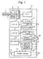
- FIG. 1 is a diagram of the system of the principal components of the patient monitor embodying the present invention.
- a sensor 1 attached to a patient detects an item of information such as blood C0 2 /oxygen tension and the detected information is fed as an electrical analogue signal through a lead L to an analogue input device 2.
- the analogue input device 2 amplifies the analogue signal and feeds the amplified analogue signal to an A/D (analogue/digital) converter 3.
- the A/D converter 3 converts the electrical analogue signal into an electrical digital signal each time the converter receives a sampling signal from a CPU 4 and feeds the electrical digital signal to the CPU 4.
- An EPROM (erasable and programmable ROM) 5 stores a program for controlling the entire system shown in Figure 1.
- a memory 6 consists of a CMOS RAM 61 and a lithium cell 62 for baking the RAM 61 up.
- the RAM 61 is provided with an area where summary data transferred from the CPU 4 are stored, an area where parameters input thereto from a key input 12 and adapted to convert the data form of the digital signal into body condition information data are stored and an area where ID (Index Data) are stored.
- the RAM 61 and CPU 4 reciprocate data therebetween.
- a real time clock circuit 7 outputs real time information relating to day, hour, minute and second and a timing signal to the CPU 4.
- the CPU 4 outputs a sampling signal at a predetermined time interval Ti based on a timing signal transmitted from the real time clock circuit 7 and obtains an electrical digital signal at the time interval from the A/D converter 3. Furthermore, the CPU 4 reads parameters corresponding to body condition information being monitored out of the RAM 61 and converts the data form of the digital signal into a measured value data in accordance with the parameters. A representative value is selected as a "summary data" from the converted data (measured value data).
- the selection of the above-mentioned summary data may be performed by extracting measured value data as summary data at a time interval n x Ti or extracting measured value data at a time interval Ti and then averaging n measured value data to obtain single summary data.
- the CPU 4 feeds the measured value data in succession to a measured value display (LCD-A) 10 which displays the same data.
- the measured value display 10 is formed of liquid crystal and has a display capacity of 7 segments x 4. Furthermore, the CPU 4 transfers summary data obtained from measured value data in a predetermined number to the RAM 61 which stores the summary data together with other data like time data representing the time when the summary data were extracted. When the obtained measured value data exhibit critical values, the CPU 4 discriminates such values and outputs an alarm signal to a sound generator 8 which in turn outputs an alarm through an amplifier 81 to an alarm speaker 82 which produces an acoustic alarm.
- the CPU 4 transfers a danger message from the EPROM 5 to a message display (LCD-B) 11 which displays the danger message.
- the message display 11 is formed of liquid crystal and has the display capacity of 16 letters x 2 lines to serve as an auxiliary unit of the display 10.
- the key input 12 has the function of presetting the above-mentioned parameters to the RAM 61as well as an additional function of instructing the RAM 61 to output summary data stored therein.
- a power source 13 is supplied with AC power from an external power supply and rectifies AC voltage to DC voltage with which a cell 14 is charged. The power source 13 also supplies necessary power to the components constituting the system.
- the cell 14 serves as the battery power source. It is to be noted that the system shown in Fig. 1 is constructed to be portable and can be effectively used as a data collection terminal unit.
- the CPU 4 Upon receiving an output demanding signal from the key input 12, the CPU 4 reads out summary data stored in the RAM 61.
- the CPU 4 edits summary data input thereto in a form, such as frequency distribution data, which can be easily read by a person monitoring it, for example, a physician.
- the CPU 4 converts the output form and outputs the converted summary data into the digital output 92 of an output region 9 with a predetermined timing determined by the CPU 4.
- the CPU 4 also edits additional information such as the days and times when summary data were sampled, ID relating to a patient and the like and converts the output form of them to be output to the digital output 92.
- the digital output 92 is a data transmission system of international standard and consists of a digital interface RS-232C.
- the output region 9 also has an analog output 91 which is adapted to be connected to a pen recorder or the like which requires an analog signal input. That is, when the analog output 91 is provided with measured value data or summary data from the CPU 4., the analog output 91 converts the data from digital into analog and outputs them as an analog signal.
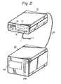
- Fig. 2 is a perspective view of the patient monitor embodying the present invention in which the main body 21 encircled by the solid line, the sensor 1, lead L, measurement display 10, message display 11 and key input 12 are indicated with numbers which correspond to those shown in Fig. 1.
- the output terminal of the digital output 92 shown in Fig. 1 is connected to a summary output exclusive recorder 23 by means of a cable 22.
- reference numeral 231 denotes a graphic printer and reference numeral 232 denotes a key input.
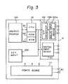
- Fig. 3 shows a diagram of the system of the principal components of the recorder 23 and the cable 22 is connected to the input terminal of a digital input 151 of the input region 15.
- the digital input 151 consists of a digital interface RS-232C. Summary data input to the digital input 151 are fed to a control 16.
- the input region 15 is provided with an analog interface 152 to process an analog input.
- the analog interface 152 consists of an analog input 152a and a V/F (voltage/frequency) converter 152b and analog data input to the input l52 are converted into digital data which are fed to the control 16.
- the control 16 consists of a CPU 161, a ROM 162 and a RAM 163. Summary data fed to the control 16 are processed in accordance with the instructions from the key input 232 in the CPU 161 and output to the graphic printer 231.
- the graphic printer 231 employs a stepping motor whereby printing and paper feed are performed by predetermined amounts at predetermined time intervals in accordance with control signals from the CPU 161. Assuming that printing is performed by one step per summary data, the printer can be controlled quite simply. In such a case, when summary data taken from the sampling time of 20 seconds are output to the graphic printer of 1/6 mm printing step, data produced during a period of 1 hour can be recorded on a chart of 30 mm.
- the graphic printer 231 is preferably a thermal graphic printer because the thermal graphic printer performs printing very quietely.
- the components of the recorder 23 are supplied with a necessary amount of power from the power source 17 which rectifies mains AC.
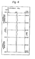
- Fig. 4 shows an example in which thermal data relating to blood C0 2/ oxygen tension are printed by the recorder 23 as body condition information.
- the patient monitor is a separate type in which the monitor main body 21 is connected to the recorder 23 by means of the cable 22, it is also contemplated by the present invention, that the monitor main body 21 of Fig. 1 and the recorder 23 of Fig. 3 may be housed in a common case.
Landscapes
- Health & Medical Sciences (AREA)
- Life Sciences & Earth Sciences (AREA)
- Physics & Mathematics (AREA)
- Molecular Biology (AREA)
- Animal Behavior & Ethology (AREA)
- Pathology (AREA)
- Engineering & Computer Science (AREA)
- Biomedical Technology (AREA)
- Heart & Thoracic Surgery (AREA)
- Medical Informatics (AREA)
- Veterinary Medicine (AREA)
- Surgery (AREA)
- Biophysics (AREA)
- General Health & Medical Sciences (AREA)
- Public Health (AREA)
- Cardiology (AREA)
- Physiology (AREA)
- Optics & Photonics (AREA)
- Vascular Medicine (AREA)
- Measuring And Recording Apparatus For Diagnosis (AREA)
Applications Claiming Priority (2)
| Application Number | Priority Date | Filing Date | Title |
|---|---|---|---|
| JP14637684A JPS6125525A (ja) | 1984-07-13 | 1984-07-13 | 患者監視装置 |
| JP146376/84 | 1984-07-13 |
Publications (2)
| Publication Number | Publication Date |
|---|---|
| EP0171927A2 true EP0171927A2 (fr) | 1986-02-19 |
| EP0171927A3 EP0171927A3 (fr) | 1987-03-04 |
Family
ID=15406312
Family Applications (1)
| Application Number | Title | Priority Date | Filing Date |
|---|---|---|---|
| EP85305000A Withdrawn EP0171927A3 (fr) | 1984-07-13 | 1985-07-12 | Appareil de surveillance pour patient |
Country Status (5)
| Country | Link |
|---|---|
| US (1) | US4779199A (fr) |
| EP (1) | EP0171927A3 (fr) |
| JP (1) | JPS6125525A (fr) |
| KR (1) | KR860001386A (fr) |
| DK (1) | DK319385A (fr) |
Cited By (2)
| Publication number | Priority date | Publication date | Assignee | Title |
|---|---|---|---|---|
| EP0336201A1 (fr) * | 1988-03-25 | 1989-10-11 | BURKE & BURKE S.N.C. DI ANTONIO BURKE E JOHN BURKE | Appareil pour conduire un test diagnostic |
| EP0251931A3 (en) * | 1986-07-01 | 1990-08-08 | Terumo Kabushiki Kaisha | Biological information measurement apparatus |
Families Citing this family (68)
| Publication number | Priority date | Publication date | Assignee | Title |
|---|---|---|---|---|
| JPS61149124A (ja) * | 1984-12-25 | 1986-07-07 | コーリン電子株式会社 | 血圧記録装置 |
| JPS62155830A (ja) * | 1985-12-28 | 1987-07-10 | テルモ株式会社 | 血圧測定装置 |
| JPS63216538A (ja) * | 1987-03-05 | 1988-09-08 | テルモ株式会社 | 心拍出量の連続測定記録装置 |
| FR2615641B1 (fr) * | 1987-05-20 | 1989-08-18 | Airbus Ind | Procede d'elaboration d'un modele statistique pour determiner la charge de travail d'un pilote d'aeronef, modele en resultant, dispositif pour la mise en oeuvre de ce procede et applications du modele |
| US4989610A (en) * | 1987-11-16 | 1991-02-05 | Spacelabs, Inc. | Method and system of ECG data review and analysis |
| US5164898A (en) * | 1988-06-10 | 1992-11-17 | Ricoh Company, Ltd. | System for determining hazardous substance exposure rate from concentration measurement and heart rate data |
| US5206807A (en) * | 1989-02-16 | 1993-04-27 | Air-Shields, Inc. | Neonatal cardiorespirograph incorporating multi-variable display and memory |
| US5144554A (en) * | 1989-03-04 | 1992-09-01 | Xueshan Zhang | Apparatus for diagnosing and providing therapy for gastrointestinal diseases without causing patient discomfort and injury |
| JPH0326231A (ja) * | 1989-06-23 | 1991-02-04 | Fukuda Denshi Co Ltd | レコーダ制御方法 |
| US5111396A (en) * | 1989-11-09 | 1992-05-05 | Instromedix, Inc. | Portable ecg data-storage apparatus |
| US5025809A (en) * | 1989-11-28 | 1991-06-25 | Cardionics, Inc. | Recording, digital stethoscope for identifying PCG signatures |
| AU4044393A (en) * | 1992-03-26 | 1993-10-21 | Homecare Diagnostic Services | Fetal monitoring system |
| US5832448A (en) | 1996-10-16 | 1998-11-03 | Health Hero Network | Multiple patient monitoring system for proactive health management |
| US20030212579A1 (en) | 2002-05-08 | 2003-11-13 | Brown Stephen J. | Remote health management system |
| US8626521B2 (en) | 1997-11-21 | 2014-01-07 | Robert Bosch Healthcare Systems, Inc. | Public health surveillance system |
| US20010011224A1 (en) | 1995-06-07 | 2001-08-02 | Stephen James Brown | Modular microprocessor-based health monitoring system |
| US8027809B2 (en) | 1992-11-17 | 2011-09-27 | Health Hero Network, Inc. | Home power management system |
| US6196970B1 (en) * | 1999-03-22 | 2001-03-06 | Stephen J. Brown | Research data collection and analysis |
| US5956501A (en) * | 1997-01-10 | 1999-09-21 | Health Hero Network, Inc. | Disease simulation system and method |
| US5951300A (en) | 1997-03-10 | 1999-09-14 | Health Hero Network | Online system and method for providing composite entertainment and health information |
| US7624028B1 (en) | 1992-11-17 | 2009-11-24 | Health Hero Network, Inc. | Remote health monitoring and maintenance system |
| US6968375B1 (en) | 1997-03-28 | 2005-11-22 | Health Hero Network, Inc. | Networked system for interactive communication and remote monitoring of individuals |
| US8078431B2 (en) | 1992-11-17 | 2011-12-13 | Health Hero Network, Inc. | Home power management system |
| US8095340B2 (en) | 1992-11-17 | 2012-01-10 | Health Hero Network, Inc. | Home power management system |
| US6330426B2 (en) | 1994-05-23 | 2001-12-11 | Stephen J. Brown | System and method for remote education using a memory card |
| US5601435A (en) * | 1994-11-04 | 1997-02-11 | Intercare | Method and apparatus for interactively monitoring a physiological condition and for interactively providing health related information |
| US8078407B1 (en) | 1997-03-28 | 2011-12-13 | Health Hero Network, Inc. | System and method for identifying disease-influencing genes |
| US7970620B2 (en) | 1992-11-17 | 2011-06-28 | Health Hero Network, Inc. | Multi-user remote health monitoring system with biometrics support |
| WO2001037174A1 (fr) | 1992-11-17 | 2001-05-25 | Health Hero Network, Inc. | Procede et systeme pour ameliorer l'observance d'un programme dietetique ou de tout autre regime medical |
| US7613590B2 (en) | 1992-11-17 | 2009-11-03 | Health Hero Network, Inc. | Modular microprocessor-based power tool system |
| US5307263A (en) | 1992-11-17 | 1994-04-26 | Raya Systems, Inc. | Modular microprocessor-based health monitoring system |
| US9215979B2 (en) | 1992-11-17 | 2015-12-22 | Robert Bosch Healthcare Systems, Inc. | Multi-user remote health monitoring system |
| US5371687A (en) * | 1992-11-20 | 1994-12-06 | Boehringer Mannheim Corporation | Glucose test data acquisition and management system |
| US5566676A (en) * | 1992-12-11 | 1996-10-22 | Siemens Medical Systems, Inc. | Pressure data acquisition device for a patient monitoring system |
| US5375604A (en) * | 1992-12-11 | 1994-12-27 | Siemens Medical Electronics, Inc. | Transportable modular patient monitor |
| CA2121413A1 (fr) * | 1993-04-22 | 1994-10-23 | Gregory A. Mckeag | Methode et systeme d'extraction en temps reel de contextes contenus dans une base de donnees |
| US5447164A (en) * | 1993-11-08 | 1995-09-05 | Hewlett-Packard Company | Interactive medical information display system and method for displaying user-definable patient events |
| US8015033B2 (en) | 1994-04-26 | 2011-09-06 | Health Hero Network, Inc. | Treatment regimen compliance and efficacy with feedback |
| US5671734A (en) * | 1995-11-03 | 1997-09-30 | The United States Of America As Represented By The Secretary Of The Navy | Automatic medical sign monitor |
| US5630664A (en) * | 1995-12-20 | 1997-05-20 | Farrelly; Patricia A. | Hand held apparatus for performing medical calculations |
| US7305348B1 (en) | 1996-02-20 | 2007-12-04 | Health Hero Network, Inc. | Aggregating and pooling health related information in a communication system with feedback |
| JP3618169B2 (ja) * | 1996-05-16 | 2005-02-09 | カシオ計算機株式会社 | 電子機器および当該電子機器を用いたシステム |
| US6039688A (en) * | 1996-11-01 | 2000-03-21 | Salus Media Inc. | Therapeutic behavior modification program, compliance monitoring and feedback system |
| US7590549B2 (en) | 1996-12-23 | 2009-09-15 | Health Hero Network, Inc. | Network media access control system for encouraging patient compliance with a treatment plan |
| US6032119A (en) | 1997-01-16 | 2000-02-29 | Health Hero Network, Inc. | Personalized display of health information |
| DE19703045A1 (de) * | 1997-01-28 | 1998-07-30 | Mueller & Sebastiani Elek Gmbh | Medizinisches Diagnosegerät |
| US6246966B1 (en) * | 1998-04-06 | 2001-06-12 | Bayer Corporation | Method and apparatus for data management authentication in a clinical analyzer |
| US8521546B2 (en) | 1998-09-25 | 2013-08-27 | Health Hero Network | Dynamic modeling and scoring risk assessment |
| JP4891511B2 (ja) * | 2000-03-29 | 2012-03-07 | ユニバーシテイ・オブ・バージニア・パテント・フアウンデーシヨン | 自己モニタリングデータから糖尿病の血糖管理を評価する方法、システム及びコンピユータプログラム製品 |
| US7013178B2 (en) | 2002-09-25 | 2006-03-14 | Medtronic, Inc. | Implantable medical device communication system |
| US7139613B2 (en) | 2002-09-25 | 2006-11-21 | Medtronic, Inc. | Implantable medical device communication system with pulsed power biasing |
| US7260480B1 (en) | 2003-04-07 | 2007-08-21 | Health Hero Network, Inc. | Method and system for integrating feedback loops in medical knowledge development and healthcare management |
| US7399276B1 (en) | 2003-05-08 | 2008-07-15 | Health Hero Network, Inc. | Remote health monitoring system |
| US7286884B2 (en) | 2004-01-16 | 2007-10-23 | Medtronic, Inc. | Implantable lead including sensor |
| WO2007081853A2 (fr) * | 2006-01-05 | 2007-07-19 | University Of Virginia Patent Foundation | Méthode, système et programme informatique d’évaluation des variations de la glycémie chez les diabétiques, à partir de donné d'auto-contrôle |
| US20070276197A1 (en) * | 2006-05-24 | 2007-11-29 | Lifescan, Inc. | Systems and methods for providing individualized disease management |
| US20080082024A1 (en) * | 2006-09-28 | 2008-04-03 | Meyer Peter F | Signal replication medical apparatus |
| US20080154513A1 (en) * | 2006-12-21 | 2008-06-26 | University Of Virginia Patent Foundation | Systems, Methods and Computer Program Codes for Recognition of Patterns of Hyperglycemia and Hypoglycemia, Increased Glucose Variability, and Ineffective Self-Monitoring in Diabetes |
| US20080234943A1 (en) * | 2007-03-20 | 2008-09-25 | Pinaki Ray | Computer program for diabetes management |
| US8758245B2 (en) * | 2007-03-20 | 2014-06-24 | Lifescan, Inc. | Systems and methods for pattern recognition in diabetes management |
| US20080235053A1 (en) * | 2007-03-20 | 2008-09-25 | Pinaki Ray | Communication medium for diabetes management |
| US20090240127A1 (en) * | 2008-03-20 | 2009-09-24 | Lifescan, Inc. | Methods of determining pre or post meal time slots or intervals in diabetes management |
| US8396563B2 (en) | 2010-01-29 | 2013-03-12 | Medtronic, Inc. | Clock synchronization in an implantable medical device system |
| JP5139461B2 (ja) * | 2010-03-11 | 2013-02-06 | 日立建機株式会社 | 作業機械のマフラ水抜き装置 |
| US9351670B2 (en) | 2012-12-31 | 2016-05-31 | Abbott Diabetes Care Inc. | Glycemic risk determination based on variability of glucose levels |
| US10383580B2 (en) | 2012-12-31 | 2019-08-20 | Abbott Diabetes Care Inc. | Analysis of glucose median, variability, and hypoglycemia risk for therapy guidance |
| EP4420603A3 (fr) | 2013-03-15 | 2024-11-20 | Abbott Diabetes Care, Inc. | Système et procédé de gestion du diabète sur la base de médiane du glucose, de la variabilité du glucose et du risque hypoglycémique |
| KR20200134702A (ko) | 2019-05-23 | 2020-12-02 | 조선기기주식회사 | 환자 모니터링 시스템 |
Family Cites Families (6)
| Publication number | Priority date | Publication date | Assignee | Title |
|---|---|---|---|---|
| DE2755643A1 (de) * | 1977-12-14 | 1979-06-21 | Zeiss Carl Fa | Verfahren und anordnung zur elektronischen langzeit-herzueberwachung |
| US4228506A (en) * | 1978-11-09 | 1980-10-14 | Del Mar Avionics | Charter with automatic editing |
| GB2054861B (en) * | 1979-07-09 | 1983-04-07 | Del Mar Avionics | Portable data aquisition and storage system for monitoring patient |
| US4417306A (en) * | 1980-01-23 | 1983-11-22 | Medtronic, Inc. | Apparatus for monitoring and storing utilizing a data processor |
| US4364397A (en) * | 1980-01-23 | 1982-12-21 | Medtronic, Inc. | Apparatus for monitoring the rhythm of a patient's heartbeat |
| US4513295A (en) * | 1983-10-21 | 1985-04-23 | American Home Products Corporation (Del.) | Method for recording medical information on a strip chart |
-
1984
- 1984-07-13 JP JP14637684A patent/JPS6125525A/ja active Pending
-
1985
- 1985-07-04 KR KR1019850004792A patent/KR860001386A/ko not_active Withdrawn
- 1985-07-12 DK DK319385A patent/DK319385A/da not_active Application Discontinuation
- 1985-07-12 EP EP85305000A patent/EP0171927A3/fr not_active Withdrawn
-
1986
- 1986-09-08 US US06/904,371 patent/US4779199A/en not_active Expired - Fee Related
Cited By (3)
| Publication number | Priority date | Publication date | Assignee | Title |
|---|---|---|---|---|
| EP0251931A3 (en) * | 1986-07-01 | 1990-08-08 | Terumo Kabushiki Kaisha | Biological information measurement apparatus |
| US5126937A (en) * | 1986-07-01 | 1992-06-30 | Terumo Kabushiki Kaisha | Biological information measurement apparatus |
| EP0336201A1 (fr) * | 1988-03-25 | 1989-10-11 | BURKE & BURKE S.N.C. DI ANTONIO BURKE E JOHN BURKE | Appareil pour conduire un test diagnostic |
Also Published As
| Publication number | Publication date |
|---|---|
| DK319385A (da) | 1986-01-14 |
| JPS6125525A (ja) | 1986-02-04 |
| EP0171927A3 (fr) | 1987-03-04 |
| DK319385D0 (da) | 1985-07-12 |
| KR860001386A (ko) | 1986-02-26 |
| US4779199A (en) | 1988-10-18 |
Similar Documents
| Publication | Publication Date | Title |
|---|---|---|
| US4779199A (en) | Patient monitor | |
| US4546436A (en) | Portable pH data collector | |
| AU617862B2 (en) | Apparatus for monitoring storing and transmitting detected physiological information | |
| KR100197580B1 (ko) | 무선 통신망을 이용한 실시간 생체신호모니터링시스템 | |
| US4858617A (en) | Cardiac probe enabling use of personal computer for monitoring heart activity or the like | |
| US5226424A (en) | Low energy consumptive device for acquisition of data relating to abnormal heart muscle activity | |
| US4624263A (en) | Portable electrocardiograph with digitally-printing waveform display | |
| US4958640A (en) | Method and apparatus for correlating the display of information contained in two information signals | |
| WO1988005282A1 (fr) | Appareil portatif de controle des fonctions physiologiques | |
| US6421558B1 (en) | Uterine activity monitor and method of the same | |
| US5123419A (en) | Combined pacemaker parameter and vital sign monitor and method of display | |
| JPS60103936A (ja) | 心電位記録装置 | |
| ATE203383T1 (de) | Druck-datenüberwachungsgerät für patienten- überwachungssystem | |
| JPH03502893A (ja) | モジュール式生理モニタ | |
| GB2181554A (en) | ECG machine | |
| JP4949575B2 (ja) | 生理学的イベント検出器及びその動作プログラム | |
| EP1394686B1 (fr) | Système pour l' acquisition des images endoscopiques | |
| JPH1156801A (ja) | 携帯型プログラマブル生体情報長期計測・記憶システム | |
| EP0299667A1 (fr) | Appareil électrocardiographique portatif | |
| JP3787022B2 (ja) | 心電図確認システム | |
| WO1989000061A1 (fr) | Moniteur de parametre de stimulateur cardiaque et de signes vitaux combines | |
| JPH01270851A (ja) | 携帯型心電計 | |
| KR900003923Y1 (ko) | 환자 감시장치 | |
| HU200272B (en) | Method and instrument for external measuring of uterus retractions | |
| JPH1057331A (ja) | デジタルホルタ心電計及びデジタルホルタ心電計における心電図信号表示方法 |
Legal Events
| Date | Code | Title | Description |
|---|---|---|---|
| PUAI | Public reference made under article 153(3) epc to a published international application that has entered the european phase |
Free format text: ORIGINAL CODE: 0009012 |
|
| AK | Designated contracting states |
Designated state(s): CH DE FR GB IT LI |
|
| PUAL | Search report despatched |
Free format text: ORIGINAL CODE: 0009013 |
|
| AK | Designated contracting states |
Kind code of ref document: A3 Designated state(s): CH DE FR GB IT LI |
|
| 17P | Request for examination filed |
Effective date: 19870821 |
|
| STAA | Information on the status of an ep patent application or granted ep patent |
Free format text: STATUS: THE APPLICATION IS DEEMED TO BE WITHDRAWN |
|
| 18D | Application deemed to be withdrawn |
Effective date: 19890202 |
|
| RIN1 | Information on inventor provided before grant (corrected) |
Inventor name: YONEDA, KIWAMU Inventor name: KUWA, KAZUHIRO |