EP0171931A1 - Instruments avec des aimants mobiles - Google Patents
Instruments avec des aimants mobiles Download PDFInfo
- Publication number
- EP0171931A1 EP0171931A1 EP85305029A EP85305029A EP0171931A1 EP 0171931 A1 EP0171931 A1 EP 0171931A1 EP 85305029 A EP85305029 A EP 85305029A EP 85305029 A EP85305029 A EP 85305029A EP 0171931 A1 EP0171931 A1 EP 0171931A1
- Authority
- EP
- European Patent Office
- Prior art keywords
- guide
- instrument
- transducing element
- bore
- spring
- Prior art date
- Legal status (The legal status is an assumption and is not a legal conclusion. Google has not performed a legal analysis and makes no representation as to the accuracy of the status listed.)
- Granted
Links
- 230000002265 prevention Effects 0.000 claims abstract description 12
- 230000002463 transducing effect Effects 0.000 claims description 23
- 230000015572 biosynthetic process Effects 0.000 claims description 2
- 238000005755 formation reaction Methods 0.000 claims description 2
- 230000005355 Hall effect Effects 0.000 description 1
- 238000006243 chemical reaction Methods 0.000 description 1
- 230000006835 compression Effects 0.000 description 1
- 238000007906 compression Methods 0.000 description 1
- 239000012530 fluid Substances 0.000 description 1
- 230000005484 gravity Effects 0.000 description 1
- 239000004973 liquid crystal related substance Substances 0.000 description 1
- 230000013011 mating Effects 0.000 description 1
Images

Classifications
-
- G—PHYSICS
- G01—MEASURING; TESTING
- G01F—MEASURING VOLUME, VOLUME FLOW, MASS FLOW OR LIQUID LEVEL; METERING BY VOLUME
- G01F1/00—Measuring the volume flow or mass flow of fluid or fluent solid material wherein the fluid passes through a meter in a continuous flow
- G01F1/05—Measuring the volume flow or mass flow of fluid or fluent solid material wherein the fluid passes through a meter in a continuous flow by using mechanical effects
- G01F1/20—Measuring the volume flow or mass flow of fluid or fluent solid material wherein the fluid passes through a meter in a continuous flow by using mechanical effects by detection of dynamic effects of the flow
- G01F1/22—Measuring the volume flow or mass flow of fluid or fluent solid material wherein the fluid passes through a meter in a continuous flow by using mechanical effects by detection of dynamic effects of the flow by variable-area meters, e.g. rotameters
- G01F1/24—Measuring the volume flow or mass flow of fluid or fluent solid material wherein the fluid passes through a meter in a continuous flow by using mechanical effects by detection of dynamic effects of the flow by variable-area meters, e.g. rotameters with magnetic or electric coupling to the indicating device
Definitions
- This invention relates to instruments with moving magnets, such as flowmeters or pressure gauges, in which at least one bar magnet is housed within a linearly-movable characteristic-responsive element (hereinafter referred to as the "transducing element"), such as a plunger or piston, movable, as by fluid flow or pressure, in a guide extending parallel to the magnet against a spring urge (or gravity), indicating means being actuated by a change in magnetic field as the magnet moves, such as a pointer on a scale - as in GB-PS 8134799 - or electronic conversion to a digital display - as in GB-PS 2 123 964A.
- a linearly-movable characteristic-responsive element such as a plunger or piston
- indicating means being actuated by a change in magnetic field as the magnet moves, such as a pointer on a scale - as in GB-PS 8134799 - or electronic conversion to a digital display - as in GB-PS 2 123 964A.
- the object of the invention is to provide means whereby consistent readings of the indicating means are ensured for any specific linear position of the transducing element relative to the indicating means.
- means is provided to prevent rotation of the transducing element with respect to the guide.
- the invention takes account of the fact that the magnetic field at any position along a bar magnet is liable to vary around the magnet axis through 360 0 .
- the rotation prevention means may comprise positively locating engagements between a part of a spring and the transducing element and between another part of the spring and the guide.
- a coil compression spring may have non-helical end portions engaging non-concentric formations on the transducing element and the guide, e.g. chordal end portions engaging flats, or longitudinally-extending end portions engaging non-axial holes.
- the rotation prevention means may be a splined engagement between the transducing element and the guide, e.g., balls located in depressions in the plunger engaging longitudinal grooves in the guide, or the transducing element may have a portion of non-circular cross-section,e.g., square with bevelled or rounded corners, slidable in a bore of similar cross-section in the guide.
- the rotation prevention means may be a rod extending parallel to the transducing element and slidable in a bore extending parallel to the guide, with the rod extending as an outrigger from the transducing element into a bore alongside the guide, or with the rod extending from a support fixed in relation to the guide into a bore in the transducing element offset from its axis.
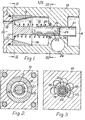
- the flowmeter comprises a body 10, an inlet 11 leading to the smaller diameter end 12 of a tapered passage 13 in the body leading to an outlet 14, and annular seating 15 at the smaller end of the tapered passage and facing towards the larger end 16, a circular valve member 17, a spring 18 urging the valve member towards contact with the seating, a plunger 19 coaxial with the valve member and slidable in a guide member 20 within a bore 21 in the body, -a bar magnet 22 in a coaxial bore 23 in the plunger, a screwthread 24 in the bore 23, a screw 25 mating with the screwthread for holding the magnet 22 captive in the bore.
- the bar magnet 22 is used in association with a magnetic detector consisting of either a circular magnet (not shown) or a Hall effect integrated circuit (not shown) housed in a blind bore 26 in the body, the magnetic detector being adapted to operate a pointer on a scale (not shown) or a liquid crystal display (not shown) for registering the rate of flow through the flowmeter.
- a magnetic detector consisting of either a circular magnet (not shown) or a Hall effect integrated circuit (not shown) housed in a blind bore 26 in the body, the magnetic detector being adapted to operate a pointer on a scale (not shown) or a liquid crystal display (not shown) for registering the rate of flow through the flowmeter.
- rotation prevention means for the plunger 19 comprises chordal end portions 27, 28 of the spring 18 engaging flats 29, 30, respectively in the end of plunger 19 adjacent the valve member and in the guide member 20.
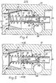
- the rotation prevention means comprises longitudinally - extending end portions 31, 32 engaging non-axial holes 33, 34 in the plunger 19 and an annular flange 35 in the guide member 20 respectively.
- the end portion 32 also extends through the flange into hole 36 in the body 10.
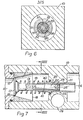
- the rotation prevention means comprises radially displaced balls 37 located in depressions 38 in the plunger 19 and engaging longitudinal grooves 39 in the guide member.
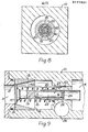
- the rotation prevention means is provided by the plunger having a portion square cross-section 40 slidable in a bore 41 of similar cross-section in the guide member.
- the rotation prevention means comprises a rod 42 extending parallel to the plunger and slidable in a bore 43 extending parallel to the guide member with the rod 42 extending as an outrigger from the plunger into the bore 43 or alternatively as in the sixth embodiment shown in Figures 10 and 11 the rod 42 extends from a support 44 fixed in relation to the guide member into a bore 45 in the plunger offset from its axis.
Landscapes
- Physics & Mathematics (AREA)
- Fluid Mechanics (AREA)
- General Physics & Mathematics (AREA)
- Measuring Volume Flow (AREA)
- Permanent Field Magnets Of Synchronous Machinery (AREA)
- Check Valves (AREA)
- Toys (AREA)
- Mixers With Rotating Receptacles And Mixers With Vibration Mechanisms (AREA)
- Magnetic Treatment Devices (AREA)
Priority Applications (1)
| Application Number | Priority Date | Filing Date | Title |
|---|---|---|---|
| AT85305029T ATE45809T1 (de) | 1984-07-17 | 1985-07-15 | Messinstrumente mit sich bewegenden magneten. |
Applications Claiming Priority (2)
| Application Number | Priority Date | Filing Date | Title |
|---|---|---|---|
| GB848418151A GB8418151D0 (en) | 1984-07-17 | 1984-07-17 | Instruments with moving magnets |
| GB8418151 | 1984-07-17 |
Publications (2)
| Publication Number | Publication Date |
|---|---|
| EP0171931A1 true EP0171931A1 (fr) | 1986-02-19 |
| EP0171931B1 EP0171931B1 (fr) | 1989-08-23 |
Family
ID=10563995
Family Applications (1)
| Application Number | Title | Priority Date | Filing Date |
|---|---|---|---|
| EP85305029A Expired EP0171931B1 (fr) | 1984-07-17 | 1985-07-15 | Instruments avec des aimants mobiles |
Country Status (4)
| Country | Link |
|---|---|
| EP (1) | EP0171931B1 (fr) |
| AT (1) | ATE45809T1 (fr) |
| DE (1) | DE3572535D1 (fr) |
| GB (2) | GB8418151D0 (fr) |
Cited By (9)
| Publication number | Priority date | Publication date | Assignee | Title |
|---|---|---|---|---|
| EP0266025A1 (fr) * | 1986-10-28 | 1988-05-04 | Roy Mervyn Cuthbert | Débitmètre à orifice variable |
| WO1996031758A1 (fr) * | 1995-04-05 | 1996-10-10 | Cole-Parmer Instrument Company | Debitmetre a flotteur magnetique |
| WO1999028722A1 (fr) * | 1997-11-27 | 1999-06-10 | Jaakko Oskari Jakobsson | Dispositif permettant de reguler, mesurer et/ou indiquer la presence d'un ecoulement, et notamment de fuite, dans des tuyauteries |
| EP0949484A1 (fr) * | 1998-04-07 | 1999-10-13 | SPANNER-POLLUX GmbH | Débimètre |
| US7391215B2 (en) | 2002-07-11 | 2008-06-24 | Victoria Link Limited | NMR apparatus |
| WO2009090375A1 (fr) * | 2008-01-14 | 2009-07-23 | Webtec Products Ltd | Débitmètre et procédé associé |
| ITUB20153725A1 (it) * | 2015-09-18 | 2017-03-18 | Watts Ind Italia Srl | Strumento di misura della portata di un fluido |
| JP2018066665A (ja) * | 2016-10-20 | 2018-04-26 | ヤマシンフィルタ株式会社 | 差圧検出装置及び濾過装置 |
| CN112229429A (zh) * | 2019-07-15 | 2021-01-15 | 图尔克控制有限公司 | 用于传感器的固定适配器 |
Families Citing this family (3)
| Publication number | Priority date | Publication date | Assignee | Title |
|---|---|---|---|---|
| GB2195768A (en) * | 1986-10-02 | 1988-04-13 | Pilkington Brothers Plc | Hall flowmeter |
| GB9402457D0 (en) * | 1994-02-09 | 1994-03-30 | Conflow Ltd | Unit for testing mains water |
| GB2297848B (en) * | 1995-09-06 | 1997-03-05 | Spirax Sarco Ltd | Flow meters |
Citations (5)
| Publication number | Priority date | Publication date | Assignee | Title |
|---|---|---|---|---|
| DE1773851A1 (de) * | 1968-07-17 | 1971-09-09 | Fischer & Porter Gmbh | Schwebekoerperdurchflussmesser |
| DE2360097A1 (de) * | 1973-12-03 | 1975-06-12 | Grefe Gmbh Ludwig | Durchflussmesser |
| DE2432574B2 (de) * | 1974-07-06 | 1978-07-20 | Josef Heinrichs Messgeraetebau, 5000 Koeln | Durchflußmesser |
| DE2801785A1 (de) * | 1978-01-17 | 1979-07-19 | Rexroth Gmbh G L | Durchflussgeraet |
| GB2090419A (en) * | 1980-12-29 | 1982-07-07 | Hayden Nilos Conflow Ltd | Zero adjustment of flowmeters |
Family Cites Families (2)
| Publication number | Priority date | Publication date | Assignee | Title |
|---|---|---|---|---|
| GB816714A (fr) * | ||||
| GB2123964B (en) * | 1982-07-15 | 1985-11-13 | Jct Controls Ltd | Flowmeters |
-
1984
- 1984-07-17 GB GB848418151A patent/GB8418151D0/en active Pending
-
1985
- 1985-07-15 EP EP85305029A patent/EP0171931B1/fr not_active Expired
- 1985-07-15 AT AT85305029T patent/ATE45809T1/de not_active IP Right Cessation
- 1985-07-15 DE DE8585305029T patent/DE3572535D1/de not_active Expired
- 1985-07-15 GB GB08517824A patent/GB2161939A/en not_active Withdrawn
Patent Citations (5)
| Publication number | Priority date | Publication date | Assignee | Title |
|---|---|---|---|---|
| DE1773851A1 (de) * | 1968-07-17 | 1971-09-09 | Fischer & Porter Gmbh | Schwebekoerperdurchflussmesser |
| DE2360097A1 (de) * | 1973-12-03 | 1975-06-12 | Grefe Gmbh Ludwig | Durchflussmesser |
| DE2432574B2 (de) * | 1974-07-06 | 1978-07-20 | Josef Heinrichs Messgeraetebau, 5000 Koeln | Durchflußmesser |
| DE2801785A1 (de) * | 1978-01-17 | 1979-07-19 | Rexroth Gmbh G L | Durchflussgeraet |
| GB2090419A (en) * | 1980-12-29 | 1982-07-07 | Hayden Nilos Conflow Ltd | Zero adjustment of flowmeters |
Cited By (11)
| Publication number | Priority date | Publication date | Assignee | Title |
|---|---|---|---|---|
| EP0266025A1 (fr) * | 1986-10-28 | 1988-05-04 | Roy Mervyn Cuthbert | Débitmètre à orifice variable |
| US4840072A (en) * | 1986-10-28 | 1989-06-20 | Cuthbert Roy M | Variable orifice flow meter |
| WO1996031758A1 (fr) * | 1995-04-05 | 1996-10-10 | Cole-Parmer Instrument Company | Debitmetre a flotteur magnetique |
| WO1999028722A1 (fr) * | 1997-11-27 | 1999-06-10 | Jaakko Oskari Jakobsson | Dispositif permettant de reguler, mesurer et/ou indiquer la presence d'un ecoulement, et notamment de fuite, dans des tuyauteries |
| EP0949484A1 (fr) * | 1998-04-07 | 1999-10-13 | SPANNER-POLLUX GmbH | Débimètre |
| US7391215B2 (en) | 2002-07-11 | 2008-06-24 | Victoria Link Limited | NMR apparatus |
| WO2009090375A1 (fr) * | 2008-01-14 | 2009-07-23 | Webtec Products Ltd | Débitmètre et procédé associé |
| ITUB20153725A1 (it) * | 2015-09-18 | 2017-03-18 | Watts Ind Italia Srl | Strumento di misura della portata di un fluido |
| JP2018066665A (ja) * | 2016-10-20 | 2018-04-26 | ヤマシンフィルタ株式会社 | 差圧検出装置及び濾過装置 |
| CN112229429A (zh) * | 2019-07-15 | 2021-01-15 | 图尔克控制有限公司 | 用于传感器的固定适配器 |
| CN112229429B (zh) * | 2019-07-15 | 2024-03-26 | 图尔克控制有限公司 | 用于传感器的固定适配器 |
Also Published As
| Publication number | Publication date |
|---|---|
| DE3572535D1 (en) | 1989-09-28 |
| GB2161939A (en) | 1986-01-22 |
| ATE45809T1 (de) | 1989-09-15 |
| GB8517824D0 (en) | 1985-08-21 |
| EP0171931B1 (fr) | 1989-08-23 |
| GB8418151D0 (en) | 1984-08-22 |
Similar Documents
| Publication | Publication Date | Title |
|---|---|---|
| EP0171931A1 (fr) | Instruments avec des aimants mobiles | |
| US4168413A (en) | Piston detector switch | |
| US12510389B2 (en) | Scalable monolithic sensor assembly, controller, and methods of making and installing same | |
| US20080289567A1 (en) | Method and Apparatus for a Gauge for Indicating a Pressure of a Fluid | |
| SE440538B (sv) | Elektrohydraulisk proportioneringsventil | |
| US4899593A (en) | Electrode structure for electromagnetic flowmeter | |
| JP2008286794A (ja) | 圧力指示装置 | |
| SU587881A3 (ru) | Индикатор дифференциального давлени | |
| CN208634500U (zh) | 行程指示器及轴流式调压阀 | |
| DE102006062858B4 (de) | Baueinheit bestehend aus einem Anschlußstück und einem mechanischen Strömungssensor | |
| JP2002513901A (ja) | 制御弁内のピストン用封入インジケータ | |
| SE455886B (sv) | Magnetoelastisk kraftgivare | |
| EP0124218A1 (fr) | Détecteur de débit | |
| US4481806A (en) | Detector for a meter prover | |
| GB1591690A (en) | Flowmeters | |
| GB2289115A (en) | Hydraulic force-applying device with thrust indicator | |
| EP0266025B1 (fr) | Débitmètre à orifice variable | |
| EP0300833A1 (fr) | Indication de la pression différentielle des unités d'écoulement de fluide | |
| EP0431975A1 (fr) | Transducteurs à inductance variable | |
| CN214305540U (zh) | 一种柔性冗余液压阀门反馈装置 | |
| EP0294157B1 (fr) | Palpeur d'écoulement d'un fluide | |
| EP1152208A1 (fr) | Dispositif de jaugeage linéaire à déplacement axial | |
| US3927476A (en) | Apparatus for checking a dimension of an object | |
| SU1756765A1 (ru) | Устройство дл контрол расхода жидкости | |
| DE102020134264A1 (de) | Sensor zum Erfassen von Druckschwankungen in einem strömenden Fluid sowie damit gebildetes Meßsystem |
Legal Events
| Date | Code | Title | Description |
|---|---|---|---|
| PUAI | Public reference made under article 153(3) epc to a published international application that has entered the european phase |
Free format text: ORIGINAL CODE: 0009012 |
|
| AK | Designated contracting states |
Designated state(s): AT BE CH DE FR GB IT LI LU NL SE |
|
| 17P | Request for examination filed |
Effective date: 19860813 |
|
| 17Q | First examination report despatched |
Effective date: 19880321 |
|
| GRAA | (expected) grant |
Free format text: ORIGINAL CODE: 0009210 |
|
| AK | Designated contracting states |
Kind code of ref document: B1 Designated state(s): AT BE CH DE FR GB IT LI LU NL SE |
|
| PG25 | Lapsed in a contracting state [announced via postgrant information from national office to epo] |
Ref country code: SE Effective date: 19890823 Ref country code: NL Effective date: 19890823 Ref country code: LI Effective date: 19890823 Ref country code: IT Free format text: LAPSE BECAUSE OF FAILURE TO SUBMIT A TRANSLATION OF THE DESCRIPTION OR TO PAY THE FEE WITHIN THE PRESCRIBED TIME-LIMIT;WARNING: LAPSES OF ITALIAN PATENTS WITH EFFECTIVE DATE BEFORE 2007 MAY HAVE OCCURRED AT ANY TIME BEFORE 2007. THE CORRECT EFFECTIVE DATE MAY BE DIFFERENT FROM THE ONE RECORDED. Effective date: 19890823 Ref country code: CH Effective date: 19890823 Ref country code: BE Effective date: 19890823 Ref country code: AT Effective date: 19890823 |
|
| REF | Corresponds to: |
Ref document number: 45809 Country of ref document: AT Date of ref document: 19890915 Kind code of ref document: T |
|
| REF | Corresponds to: |
Ref document number: 3572535 Country of ref document: DE Date of ref document: 19890928 |
|
| REG | Reference to a national code |
Ref country code: CH Ref legal event code: PL |
|
| ET | Fr: translation filed | ||
| NLV1 | Nl: lapsed or annulled due to failure to fulfill the requirements of art. 29p and 29m of the patents act | ||
| PLBE | No opposition filed within time limit |
Free format text: ORIGINAL CODE: 0009261 |
|
| STAA | Information on the status of an ep patent application or granted ep patent |
Free format text: STATUS: NO OPPOSITION FILED WITHIN TIME LIMIT |
|
| PGFP | Annual fee paid to national office [announced via postgrant information from national office to epo] |
Ref country code: FR Payment date: 19900712 Year of fee payment: 6 |
|
| PG25 | Lapsed in a contracting state [announced via postgrant information from national office to epo] |
Ref country code: LU Free format text: LAPSE BECAUSE OF NON-PAYMENT OF DUE FEES Effective date: 19900731 |
|
| 26N | No opposition filed | ||
| PGFP | Annual fee paid to national office [announced via postgrant information from national office to epo] |
Ref country code: GB Payment date: 19910702 Year of fee payment: 7 |
|
| PGFP | Annual fee paid to national office [announced via postgrant information from national office to epo] |
Ref country code: DE Payment date: 19910709 Year of fee payment: 7 |
|
| PG25 | Lapsed in a contracting state [announced via postgrant information from national office to epo] |
Ref country code: FR Effective date: 19920331 |
|
| REG | Reference to a national code |
Ref country code: FR Ref legal event code: ST |
|
| PG25 | Lapsed in a contracting state [announced via postgrant information from national office to epo] |
Ref country code: GB Effective date: 19920715 |
|
| GBPC | Gb: european patent ceased through non-payment of renewal fee |
Effective date: 19920715 |
|
| PG25 | Lapsed in a contracting state [announced via postgrant information from national office to epo] |
Ref country code: DE Effective date: 19930401 |