EP0172019B1 - Walze für Erdbau und Bodenverdichtung mit leicht ersetzbaren Schaffussvorrichtungen - Google Patents
Walze für Erdbau und Bodenverdichtung mit leicht ersetzbaren Schaffussvorrichtungen Download PDFInfo
- Publication number
- EP0172019B1 EP0172019B1 EP85305741A EP85305741A EP0172019B1 EP 0172019 B1 EP0172019 B1 EP 0172019B1 EP 85305741 A EP85305741 A EP 85305741A EP 85305741 A EP85305741 A EP 85305741A EP 0172019 B1 EP0172019 B1 EP 0172019B1
- Authority
- EP
- European Patent Office
- Prior art keywords
- cap unit
- base portion
- locking means
- bracket
- roller
- Prior art date
- Legal status (The legal status is an assumption and is not a legal conclusion. Google has not performed a legal analysis and makes no representation as to the accuracy of the status listed.)
- Expired - Lifetime
Links
- 238000005056 compaction Methods 0.000 title claims abstract description 15
- 230000000712 assembly Effects 0.000 title claims abstract description 13
- 238000000429 assembly Methods 0.000 title claims abstract description 13
- 230000008878 coupling Effects 0.000 claims abstract description 31
- 238000010168 coupling process Methods 0.000 claims abstract description 31
- 238000005859 coupling reaction Methods 0.000 claims abstract description 31
- 230000002401 inhibitory effect Effects 0.000 claims abstract 2
- CNJLMVZFWLNOEP-UHFFFAOYSA-N 4,7,7-trimethylbicyclo[4.1.0]heptan-5-one Chemical compound O=C1C(C)CCC2C(C)(C)C12 CNJLMVZFWLNOEP-UHFFFAOYSA-N 0.000 description 1
- 238000005452 bending Methods 0.000 description 1
- 238000004140 cleaning Methods 0.000 description 1
- 230000001066 destructive effect Effects 0.000 description 1
- 230000037431 insertion Effects 0.000 description 1
- 238000003780 insertion Methods 0.000 description 1
- 230000002093 peripheral effect Effects 0.000 description 1
Images

Classifications
-
- E—FIXED CONSTRUCTIONS
- E02—HYDRAULIC ENGINEERING; FOUNDATIONS; SOIL SHIFTING
- E02D—FOUNDATIONS; EXCAVATIONS; EMBANKMENTS; UNDERGROUND OR UNDERWATER STRUCTURES
- E02D3/00—Improving or preserving soil or rock, e.g. preserving permafrost soil
- E02D3/02—Improving by compacting
- E02D3/026—Improving by compacting by rolling with rollers usable only for or specially adapted for soil compaction, e.g. sheepsfoot rollers
Definitions
- This invention concerns generally compaction machinery such as a roller for mounting upon a driven compaction vehicle, the roller having both destructive and tractive characteristics adapted to break up, crush, grind and compact materials of the size of home appliances as encountered in sanitary land fill operations.
- Compaction rollers and wheels used on land fill operations and particularly sanitary land fill operations are equipped generally with cleats or feet of a type for grinding and crushing the material beneath it so as to reduce the material in size for compaction.
- cleats or feet of a type for grinding and crushing the material beneath it so as to reduce the material in size for compaction.
- an earth and sanitary fill compaction roller has been shown employing two different types of feet having replaceable wear caps as part of its cleat assemblies. The wear caps are welded to a base portion of the assembly which in turn is welded to the roller.
- a fill and compaction roller of a type having a rigid cylindrical body supported for rotation from a vehicle chassis and having cleat assemblies carried by the body, the cleat assemblies each comprising a rigid mounting pad assembly having a base portion attached to said body and a cap unit releasably attached to the base portion by a coupling pin, each cleat assembly including a bracket integral to said base portion protruding radially outwardly therefrom and having a coupling opening extending transversely through the bracket, and wherein the cap unit comprises a generally hollow body including sloping upwardly converging outer side walls and transverse end walls extending between the end edges of said side walls, a pair of aligned openings respectively being formed through the side walls and aligned with said coupling opening for receiving the coupling pin therethrough, which coupling pin being disposed through said coupling opening and said aligned openings to retain said cap unit to said mounting pad assembly, and there being further provided annular recesses surrounding each end of
- a fill and compaction roller is characterised by further including means serving to closely guide said cap unit on to said bracket including a pair of confronting substantially parallel abutments extending radially outwardly along the inner surface of the confronting sloping walls of the hollow body of said cap unit, said aligned openings being disposed to extend through said abutments, said bracket having a pair of transverse flanges flanking each end of said coupling opening to form a guide slot at opposite ends of the opening for receiving an associated one of said abutments slidable therein, said abutments being closely spaced to said locking means to capture and retain said locking means in their associated recesses.
- each said locking means comprises a split ring disposed within each said recess.
- An advantage of such an arrangement is that a compaction roller has been provided wherein the wear cap can be readily removed using common tools available at the job site. In this way replacement of the wear caps before the supporting base becomes worn to a point requiring its removal has been encouraged.
- the rigid mounting pad assembly has a base portion adapted to be welded to the body.
- An advantage of the invention is to provide a cleat assembly of a type requiring minimal time and labor to replace using ordinary tools.
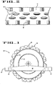
- the roller assembly 10 is represented diagrammatically and can be constructed according to U.S. Patent No. 3,724,342 assigned to Caron Compactor Company to incorporate cushioning elements, cleaning members, and the like.
- Roller 10 has been mounted upon a perimeter frame 14 of vehicle 13.
- Frame 14 is of a type including cross members 16,17 extending across the tread of the roller 10.
- Cleat assemblies 18, 19 as described more fully below are arranged on the outer surface of the cylindrical rim 11. Cleat assemblies 18 primarily serve to provide traction while the primary function of assemblies 19 is to crush materials.
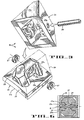
- cleat assembly 18 includes a rigid mounting pad unit 21 having a base portion 22 curved along edge 21a to conform to the curvature of rim 11 so as to be adapted to be welded to the rigid body formed by rim 11.
- a bracket 23 formed integral with base portion 22 protrudes generally radially outwardly therefrom.
- a coupling opening 24 extends trnasversely of bracket 23 and enlarged annular recesses 26 surround each end of opening 24.
- wear cap unit 29 is adapted to be readily releasably coupled to base portion 22.
- Wear cap unit 29 has a generally hollow body including sloping upwardly converging outer side walls 29a and transverse end walls 29b extending between the end edges of side walls 29a.
- a pair of aligned openings 31 extend through side walls 29a in position to be aligned with coupling opening 24 of bracket 23. In this way coupling pin 28 can be readily disposed to extend through openings 31 and 24 to couple wear cap unit 29 to its mounting pad unit 21.
- Means for readily releasably locking pin 28 in openings 31, 24 serves to prevent decoupling of cap unit 29 from pad assembly 21 as now to be described.
- a hammer can be used to drive a screw driver against an end of pin 28 to move it through cap unit 29 until pin 28 is released from split rings 27.
- cap unit 29 means have been provided serving to closely guide cap unit 29 onto bracket 23. Accordingly a pair of confronting substantially parallel abutments 32, 33 extend radially outwardly along the inner surface of the confronting sloping walls 29a of the hollow body of cap unit 29.
- openings 31 extend through these abutments in alignment with coupling opening 24 of bracket 23.
- the confronting faces 23a, 23b of a pair of transverse flanges flank each end of coupling opening 24 to form a guide slot at opposite ends of opening 24 for receiving an associated one of abutments 32, 33.
- Bracket 23 includes a registration surface or face 23c extending between the confronting faces 23a, 23b.
- cap unit 29 has been disposed onto bracket 23 as represented by the phantom lines 34 in Figure 3 the opposed faces of abutments 32, 33 will be disposed in closely spaced relation to the registration surfaces 23c of bracket 23 so as to fully capture split rings 27 in their respective recesses 26.
- bracket 23 includes a pair of "slots" on opposite sides of the bracket for receiving abutments 32, 33.
- the "slots" are defined by the wall faces 23a, 23b and 23c. Accordingly, these guide “slots" serve to receive an associated one of the abutments closely spaced therein.
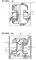
- a cleat assembly 19 primarily used for crushing, breaking and grinding of materials of the size of home appliances as encountered in sanitary land fill operations includes a rigid mounting pad unit 37 including a rigid metallic base portion 38.
- Base portion 38 supports an elongate relatively thin aligning guide 39 formed integrally with base portion 38.
- Aligning guide 39 includes an upwardly extending bracket portion 41 characterized by an upwardly protruding key 42 disposed within a downwardly opening pocket 43 defined within a removable wear cap 44.
- aligning guide 39 serves to provide three spaced' points of support as now to be described.
- the hollow interior 46 of cap 44 slopes downwardly and-away to form a notch 47, 48 for receiving the tip ends 49, 51 of guide 39. Accordingly, as thus mounted, by lodging the tips 49, 51 in notches 47,48 wear cap 44 is restrained against being twisted relatively to base portion 38 about an axis normal thereto, such as axis 52.
- key 42 engaged in pocket 43 serves to restrain wear cap 44 from being twisted laterally with respect to base portion 38, for example, as about the axis 53 parallel to base portion 38.
- a coupling pin 54 extends through an opening disposed transversely of bracket portion 41 as described above with regard to bracket 23.
- Each end of the coupling opening 56 is similarly surrounded by an annular recess 57.
- Coupling pin 54 accordingly retains wear cap 44 to mounting pad assembly 37.
- base portion 38 is arcuately formed to conform to the peripheral surface of rim 11 and adapted to be welded thereto.
Landscapes
- Engineering & Computer Science (AREA)
- Structural Engineering (AREA)
- Life Sciences & Earth Sciences (AREA)
- Paleontology (AREA)
- Soil Sciences (AREA)
- Environmental & Geological Engineering (AREA)
- General Life Sciences & Earth Sciences (AREA)
- Mining & Mineral Resources (AREA)
- Agronomy & Crop Science (AREA)
- Civil Engineering (AREA)
- General Engineering & Computer Science (AREA)
- Road Repair (AREA)
- Soil Working Implements (AREA)
- Investigation Of Foundation Soil And Reinforcement Of Foundation Soil By Compacting Or Drainage (AREA)
- Massaging Devices (AREA)
- Road Paving Machines (AREA)
Claims (5)
Priority Applications (1)
| Application Number | Priority Date | Filing Date | Title |
|---|---|---|---|
| AT85305741T ATE54693T1 (de) | 1984-08-13 | 1985-08-13 | Walze fuer erdbau und bodenverdichtung mit leicht ersetzbaren schaffussvorrichtungen. |
Applications Claiming Priority (2)
| Application Number | Priority Date | Filing Date | Title |
|---|---|---|---|
| US63984884A | 1984-08-13 | 1984-08-13 | |
| US639848 | 1984-08-13 |
Publications (3)
| Publication Number | Publication Date |
|---|---|
| EP0172019A2 EP0172019A2 (de) | 1986-02-19 |
| EP0172019A3 EP0172019A3 (en) | 1987-02-25 |
| EP0172019B1 true EP0172019B1 (de) | 1990-07-18 |
Family
ID=24565809
Family Applications (1)
| Application Number | Title | Priority Date | Filing Date |
|---|---|---|---|
| EP85305741A Expired - Lifetime EP0172019B1 (de) | 1984-08-13 | 1985-08-13 | Walze für Erdbau und Bodenverdichtung mit leicht ersetzbaren Schaffussvorrichtungen |
Country Status (6)
| Country | Link |
|---|---|
| EP (1) | EP0172019B1 (de) |
| JP (1) | JPS61113919A (de) |
| AT (1) | ATE54693T1 (de) |
| AU (1) | AU591873B2 (de) |
| CA (1) | CA1257800A (de) |
| DE (1) | DE3578708D1 (de) |
Families Citing this family (9)
| Publication number | Priority date | Publication date | Assignee | Title |
|---|---|---|---|---|
| DE3540183A1 (de) * | 1985-11-13 | 1987-05-21 | Viehmann & Co Intertrac | Muellverdichtungsfahrzeug |
| AU582700B2 (en) * | 1986-09-15 | 1989-04-06 | South African Inventions Development Corporation | Compaction roller assembly |
| US6682262B2 (en) * | 2000-05-05 | 2004-01-27 | Caron Compactor Company | Fill and compaction roller using replaceable cleat assemblies with extended service life |
| US6712551B2 (en) * | 2001-11-27 | 2004-03-30 | Caterpillar Inc | Compactor tooth |
| US6619883B2 (en) * | 2001-11-27 | 2003-09-16 | Caterpillar Inc | Compactor tooth |
| US20060255653A1 (en) | 2004-09-02 | 2006-11-16 | John Gibbins | Replacement Part Assembly |
| US20120213586A1 (en) * | 2011-02-23 | 2012-08-23 | Caterpillar, Inc. | Wrapper Tip Assembly For Compactor Wheel Assembly |
| JP6054114B2 (ja) * | 2012-09-20 | 2016-12-27 | 飛島建設株式会社 | キャピラリーバリア多層地盤における集排水制御構造の構築方法 |
| US20150330049A1 (en) * | 2014-05-16 | 2015-11-19 | Caterpillar Inc. | Compactor wheel having multi-zone tip configuration |
Family Cites Families (7)
| Publication number | Priority date | Publication date | Assignee | Title |
|---|---|---|---|---|
| US1371303A (en) * | 1920-06-23 | 1921-03-15 | Emerson Moses Mancil | Tamping-roller |
| US2312471A (en) * | 1940-08-03 | 1943-03-02 | John J Low | Sheep foot tamper |
| US3274908A (en) * | 1964-07-22 | 1966-09-27 | Caterpillar Tractor Co | Tamping device |
| DE1297042B (de) * | 1965-06-03 | 1969-06-04 | Caterpillar Tractor Co | Schaffuss fuer Schaffusswalze |
| US3358569A (en) * | 1965-07-30 | 1967-12-19 | James R Tweedy | Sheep foot tamper |
| CA995041A (en) * | 1972-10-24 | 1976-08-17 | Caron Compactor Co. | Earth compaction pads |
| US3922106A (en) * | 1974-04-22 | 1975-11-25 | Caron Compactor Co | Compaction wheel with traction and crushing characteristics |
-
1985
- 1985-08-12 CA CA000488546A patent/CA1257800A/en not_active Expired
- 1985-08-12 AU AU46104/85A patent/AU591873B2/en not_active Expired
- 1985-08-13 EP EP85305741A patent/EP0172019B1/de not_active Expired - Lifetime
- 1985-08-13 DE DE8585305741T patent/DE3578708D1/de not_active Expired - Lifetime
- 1985-08-13 AT AT85305741T patent/ATE54693T1/de active
- 1985-08-13 JP JP60178459A patent/JPS61113919A/ja active Granted
Also Published As
| Publication number | Publication date |
|---|---|
| EP0172019A2 (de) | 1986-02-19 |
| CA1257800A (en) | 1989-07-25 |
| JPH0343407B2 (de) | 1991-07-02 |
| DE3578708D1 (de) | 1990-08-23 |
| AU4610485A (en) | 1986-02-20 |
| JPS61113919A (ja) | 1986-05-31 |
| ATE54693T1 (de) | 1990-08-15 |
| AU591873B2 (en) | 1989-12-21 |
| EP0172019A3 (en) | 1987-02-25 |
Similar Documents
| Publication | Publication Date | Title |
|---|---|---|
| CA2465480C (en) | Fill and compaction roller using replaceable cleat assemblies with extended service life | |
| EP1283924B1 (de) | Walze für erdbau und bodenverdichtung mit austauschbaren bügeln für ausgedehnte nutzungsdauer | |
| US4919566A (en) | Fill and compaction roller using readily replaceable cleat assemblies | |
| AU706813B2 (en) | Improved transfer station wheels | |
| US5884979A (en) | Cutting bit holder and support surface | |
| AU2001259468A1 (en) | Extended wear anti-twist replaceable compactor cleats | |
| EP0860552B1 (de) | Vorrichtung zur Rückgewinnung von Strassenbelägen mit einer Fräswalze | |
| US6837649B2 (en) | Compactor tooth | |
| EP0172019B1 (de) | Walze für Erdbau und Bodenverdichtung mit leicht ersetzbaren Schaffussvorrichtungen | |
| US5098167A (en) | Tool block with non-rotating, replaceable wear insert/block | |
| US3922106A (en) | Compaction wheel with traction and crushing characteristics | |
| US8333439B2 (en) | Replacement part assembly | |
| EP0462485A2 (de) | Verbesserte Werkzeugträgeranordnung und Zahnhalter | |
| US20050225162A1 (en) | Compaction wheel and cleat assembly therefor | |
| US20040114999A1 (en) | Cleaner finger assembly and mounting for same | |
| US6652186B2 (en) | Cleat assembly for trash compactor vehicle wheels | |
| AU2021273636B2 (en) | Roller tool for a soil cultivation roller | |
| PL242115B1 (pl) | Ząb, zwłaszcza koła kompaktora | |
| CA1036406A (en) | Compaction wheel with traction and crushing characteristics | |
| AU2004202012A1 (en) | Fill and compaction roller using replaceable cleat assemblies with extended service life |
Legal Events
| Date | Code | Title | Description |
|---|---|---|---|
| PUAI | Public reference made under article 153(3) epc to a published international application that has entered the european phase |
Free format text: ORIGINAL CODE: 0009012 |
|
| AK | Designated contracting states |
Designated state(s): AT BE CH DE FR GB IT LI NL SE |
|
| PUAL | Search report despatched |
Free format text: ORIGINAL CODE: 0009013 |
|
| AK | Designated contracting states |
Kind code of ref document: A3 Designated state(s): AT BE CH DE FR GB IT LI NL SE |
|
| 17P | Request for examination filed |
Effective date: 19870713 |
|
| 17Q | First examination report despatched |
Effective date: 19881202 |
|
| GRAA | (expected) grant |
Free format text: ORIGINAL CODE: 0009210 |
|
| ITF | It: translation for a ep patent filed | ||
| AK | Designated contracting states |
Kind code of ref document: B1 Designated state(s): AT BE CH DE FR GB IT LI NL SE |
|
| REF | Corresponds to: |
Ref document number: 54693 Country of ref document: AT Date of ref document: 19900815 Kind code of ref document: T |
|
| REF | Corresponds to: |
Ref document number: 3578708 Country of ref document: DE Date of ref document: 19900823 |
|
| ET | Fr: translation filed | ||
| PLBE | No opposition filed within time limit |
Free format text: ORIGINAL CODE: 0009261 |
|
| STAA | Information on the status of an ep patent application or granted ep patent |
Free format text: STATUS: NO OPPOSITION FILED WITHIN TIME LIMIT |
|
| 26N | No opposition filed | ||
| ITTA | It: last paid annual fee | ||
| EAL | Se: european patent in force in sweden |
Ref document number: 85305741.2 |
|
| PGFP | Annual fee paid to national office [announced via postgrant information from national office to epo] |
Ref country code: FR Payment date: 19980720 Year of fee payment: 14 |
|
| PGFP | Annual fee paid to national office [announced via postgrant information from national office to epo] |
Ref country code: SE Payment date: 19980721 Year of fee payment: 14 |
|
| PGFP | Annual fee paid to national office [announced via postgrant information from national office to epo] |
Ref country code: AT Payment date: 19980723 Year of fee payment: 14 |
|
| PGFP | Annual fee paid to national office [announced via postgrant information from national office to epo] |
Ref country code: CH Payment date: 19980727 Year of fee payment: 14 |
|
| PGFP | Annual fee paid to national office [announced via postgrant information from national office to epo] |
Ref country code: NL Payment date: 19980728 Year of fee payment: 14 |
|
| PG25 | Lapsed in a contracting state [announced via postgrant information from national office to epo] |
Ref country code: AT Free format text: LAPSE BECAUSE OF NON-PAYMENT OF DUE FEES Effective date: 19990813 |
|
| PG25 | Lapsed in a contracting state [announced via postgrant information from national office to epo] |
Ref country code: SE Free format text: THE PATENT HAS BEEN ANNULLED BY A DECISION OF A NATIONAL AUTHORITY Effective date: 19990814 |
|
| PG25 | Lapsed in a contracting state [announced via postgrant information from national office to epo] |
Ref country code: LI Free format text: LAPSE BECAUSE OF NON-PAYMENT OF DUE FEES Effective date: 19990831 Ref country code: CH Free format text: LAPSE BECAUSE OF NON-PAYMENT OF DUE FEES Effective date: 19990831 |
|
| PG25 | Lapsed in a contracting state [announced via postgrant information from national office to epo] |
Ref country code: NL Free format text: LAPSE BECAUSE OF NON-PAYMENT OF DUE FEES Effective date: 20000301 |
|
| REG | Reference to a national code |
Ref country code: CH Ref legal event code: PL |
|
| PG25 | Lapsed in a contracting state [announced via postgrant information from national office to epo] |
Ref country code: FR Free format text: LAPSE BECAUSE OF NON-PAYMENT OF DUE FEES Effective date: 20000428 |
|
| EUG | Se: european patent has lapsed |
Ref document number: 85305741.2 |
|
| NLV4 | Nl: lapsed or anulled due to non-payment of the annual fee |
Effective date: 20000301 |
|
| REG | Reference to a national code |
Ref country code: FR Ref legal event code: ST |
|
| REG | Reference to a national code |
Ref country code: GB Ref legal event code: IF02 |
|
| PGFP | Annual fee paid to national office [announced via postgrant information from national office to epo] |
Ref country code: GB Payment date: 20040804 Year of fee payment: 20 |
|
| PGFP | Annual fee paid to national office [announced via postgrant information from national office to epo] |
Ref country code: BE Payment date: 20040917 Year of fee payment: 20 |
|
| PGFP | Annual fee paid to national office [announced via postgrant information from national office to epo] |
Ref country code: DE Payment date: 20040930 Year of fee payment: 20 |
|
| PG25 | Lapsed in a contracting state [announced via postgrant information from national office to epo] |
Ref country code: GB Free format text: LAPSE BECAUSE OF EXPIRATION OF PROTECTION Effective date: 20050812 |
|
| BE20 | Be: patent expired |
Owner name: *CARON COMPACTOR CY Effective date: 20050813 |
|
| REG | Reference to a national code |
Ref country code: GB Ref legal event code: PE20 |
|
| BE20 | Be: patent expired |
Owner name: *CARON COMPACTOR CY Effective date: 20050813 |