EP0172020A2 - Wall-mounted hair dryer - Google Patents
Wall-mounted hair dryer Download PDFInfo
- Publication number
- EP0172020A2 EP0172020A2 EP85305748A EP85305748A EP0172020A2 EP 0172020 A2 EP0172020 A2 EP 0172020A2 EP 85305748 A EP85305748 A EP 85305748A EP 85305748 A EP85305748 A EP 85305748A EP 0172020 A2 EP0172020 A2 EP 0172020A2
- Authority
- EP
- European Patent Office
- Prior art keywords
- hair dryer
- handle
- switch
- casing
- wall
- Prior art date
- Legal status (The legal status is an assumption and is not a legal conclusion. Google has not performed a legal analysis and makes no representation as to the accuracy of the status listed.)
- Granted
Links
- 238000010438 heat treatment Methods 0.000 claims abstract description 6
- 239000000463 material Substances 0.000 claims description 3
- XLYOFNOQVPJJNP-UHFFFAOYSA-N water Substances O XLYOFNOQVPJJNP-UHFFFAOYSA-N 0.000 claims description 3
- 229920001870 copolymer plastic Polymers 0.000 claims description 2
- 239000003990 capacitor Substances 0.000 description 4
- 238000004804 winding Methods 0.000 description 3
- 239000011810 insulating material Substances 0.000 description 2
- 229920000122 acrylonitrile butadiene styrene Polymers 0.000 description 1
- 238000010586 diagram Methods 0.000 description 1
- 239000002184 metal Substances 0.000 description 1
- 239000002991 molded plastic Substances 0.000 description 1
- 238000013021 overheating Methods 0.000 description 1
Images

Classifications
-
- A—HUMAN NECESSITIES
- A45—HAND OR TRAVELLING ARTICLES
- A45D—HAIRDRESSING OR SHAVING EQUIPMENT; EQUIPMENT FOR COSMETICS OR COSMETIC TREATMENTS, e.g. FOR MANICURING OR PEDICURING
- A45D20/00—Hair drying devices; Accessories therefor
- A45D20/04—Hot-air producers
- A45D20/08—Hot-air producers heated electrically
- A45D20/16—Fixed installed drying devices
-
- A—HUMAN NECESSITIES
- A45—HAND OR TRAVELLING ARTICLES
- A45D—HAIRDRESSING OR SHAVING EQUIPMENT; EQUIPMENT FOR COSMETICS OR COSMETIC TREATMENTS, e.g. FOR MANICURING OR PEDICURING
- A45D20/00—Hair drying devices; Accessories therefor
- A45D20/22—Helmets with hot air supply or ventilating means, e.g. electrically heated air current
- A45D20/30—Electric circuitry specially adapted for hair drying devices
-
- A—HUMAN NECESSITIES
- A45—HAND OR TRAVELLING ARTICLES
- A45D—HAIRDRESSING OR SHAVING EQUIPMENT; EQUIPMENT FOR COSMETICS OR COSMETIC TREATMENTS, e.g. FOR MANICURING OR PEDICURING
- A45D20/00—Hair drying devices; Accessories therefor
- A45D20/52—Hair-drying combs or hair-drying brushes, adapted for heating by an external heating source, e.g. air stream
Definitions
- This invention relates to wall-mounted hair dryers.
- Present wall-mounted hairdryers such as are found, for example, in hotel bathrooms, have several disadvantages.
- One disadvantage is that if the hair dryer is left on for an extended period, it may be damaged or present a safety hazard due to overheating, apart from wasting electrical energy.
- the hair dryer is provided with a sufficiently powerful motor and heater element to be satisfactorily fast in operation, the hose and handle of the hair dryer may become uncomfortably hot in use and may need to be made uncomfortably heavy in order to withstand the heat absorbed.
- a wall-mounted hair dryer comprises a casing containing a heating element, a motor, an impeller and associated electrical circuitry, a flexible air hose terminating in a handle, the handle being provided with an outlet for directing heated air at the person of a user, means for detachably securing the handle against the casing, switching means arranged to switch on the hair dryer when the handle is detached from the casing and to switch off the hair dryer when the handle is replaced, and a timer arranged to automatically switch off the hair dryer automatically after a predetermined period of operation.
- the switching means may be a micro-switch having a linkage arranged to be operated by detachment and replacement of the handle.
- the timer is preferably an electronic timing circuit arranged to switch the electrical supply to the hair dryer through a relay.
- the hair dryer may include electrical outlets, for example for electric shavers, which are supplied from a separate electrical circuit to the main circuit of the hair dryer and which may be overload protected.
- the hair dryer is provided with an air intake in the casing, the intake being shielded by a cowl which overlaps the intake to prevent the ingress of water into the interior of the hair dryer.
- the hair dryer may include a thermostatic switch mounted near a heating element in the air path of the hair dryer and arranged to interrupt the electrical supply to the hair dryer if a preset temperature is exceeded.
- the hose is preferably made of heat resistant ABS plastics material.
- the air passage in the handle between the end of the hose and the outlet is preferably sealed from the body of the handle and thermally insulated therefrom.
- a hair dryer 10 for mounting on a surface such as a wall has a moulded plastics casing 12.
- the casing 12 is provided at its top and bottom with flanges 14 and 16 in which are provided apertures 18, 20 and 22 by means of which the hair dryer may be fastened to the surface, for example by screws.
- On the front of the casing 12 is an air intake 24 which is covered by a cowl 26.
- the cowl 26 overlaps the intake 24 and prevents water which is splashed onto the casing 12 from entering the hair dryer 10, when, for instance, the hair dryer 10 is used in a bathroom.
- outlets 28 and 30 are also provided on the front of the casing 12 for use, for example, with electric shavers.
- an air hose 32 of tough, heat resistant ABS (acrytonitrite-butadiene-styrene copolymer) plastics material.
- the hose 32 terminates in a handle 3 4 which has an air outlet 36 therein, through which heated air is exhausted when the hair dryer 10 is in operation.
- the handle 34 is mounted rotatably on the end of the hose 32.
- the air passage in the handle 3 4 is defined by a tube (not shown) which connects the end of the hose 32 to the outlet 36.
- the air passage is sealed from the body of the handle 34 and a layer of insulating material such as mica-impregnated sheeting or other insulating material insulates the handle 34 thermally from the tube. This prevents the handle 34 from becoming uncomfortably hot during use and permits the use of a heating element of higher rating than would otherwise be possible.
- the part of the handle 34 carrying the outlet 36 is shaped to fit in a recess 38 provided in the casing 12. Magnets (not shown) in the recess 38 attract a metal grille which is fixed across the outlet 36 and thereby hold the handle firmly against the casing 12 when the hair dryer 10 is not in use
- the casing 12 contains the active components of the hair dryer, including a motor and impeller assembly, a heater element with a thermostatic switch, a micro-switch, a transformer for supplying power to the outlets 28 and 30, and an electronic circuit for controlling the operation of the hair dryer 10.
- the electrical circuit of the hair dryer 10 is seen to comprise three basic sections.
- the first section includes the motor and heater element
- the second section is a circuit for controlling the operation of the first section
- the third section is an independent circuit for supplying power to the outlets 28 and 30. All three sections are connected to the mains electrical supply.
- a heater element 40 and its associated thermostatic switch 42 are connected in series with a motor circuit 44, a micro-switch 46, and the contacts 48 of a relay 50.
- the micro-switch 46 is arranged to be operated by an actuating button protruding into the recess 38 in the casing 12, and is closed when the handle 34 is removed from the recess 38, thereby connecting the heater element 40 and the motor circuit 44 to the electrical supply.
- the control circuit comprising a 12 volt transformer 52, a rectifier bridge 54, a timer circuit 56 and the relay 50 are also connected to the supply.
- the timer circuit 56 which is a conventional electronic circuit assembled on a printed circuit board, immediately pulls in the relay 50, closing the normally open contacts 48.
- the circuit including the heater element 40 and the motor circuit 44 is thus completed and the hair dryer 10 operates, providing a stream of heated air via the hose 32 and the outlet 36.
- the thermostatic switch 42 is mounted in close proximity to the heater element 40 and the normally closed contacts of the switch 42 open if the temperature in the vicinity thereof is above a predetermined limit, for example if the outlet 36 should be blocked.
- the timer circuit 56 will de-activate the relay 50, even if the handle 34 is not returned to its rest-position in the recess 38, thereby turning off the hair dryer 10.
- the user will replace the handle 34 in the recess 38, thereby opening the micro-switch 46, turning off the hair dryer 10, and resetting the timer circuit 56.
- the motor circuit 44 comprises a DC motor 58 connected between a bridge of four diodes 60, 62, 6 4 and 66. In series with the motor 58 and the bridge are two chokes 68 and 70, while a capacitor 72 and a resistor 74 are connected in parallel across the input to the bridge. Connected between the positive and negative leads of the motor 58 and a screen surrounding the motor 58 are two capacitors 76 and 78.
- the diodes 60, 62, 64 and 66 rectify the current supplied to the motor 58, while the chokes 68 and 70, the capacitor 72 and the resistor 74, and the capacitors 76 and 78 filter electrical noise generated by the motor 58.
- the motor 56 is a relatively low voltage DC motor (typically of 12 to 24 volt rating)
- the use of the diodes 60, 62, 64 and 66 permit it to be used on an AC supply.
- the relative voltage drops across the motor circuiit 44 and the heater element 40, which are connected in series and therefore form a voltage divider, are calculated so as to prevent the maximum rating of the motor 58 from being exceeded.
- the secondary windings of the transformer are connected to the outlets 28 and 30, with one outlet being supplied with the normal mains voltage and the other being supplied with either half or double the mains voltage, depending on whether the nominal mains voltage is higher or lower than that required. For example, if the mains voltage is 220 V, one outlet will be supplied with 220 V, while the other will be supplied by one half of the centre- tapped secondary winding with 110 V.
- the cutout 82 prevents more than a predetermined current, say 0,1A from being drawn from the sockets.
Landscapes
- Cleaning And Drying Hair (AREA)
- Drying Of Solid Materials (AREA)
Abstract
Description
- This invention relates to wall-mounted hair dryers. Present wall-mounted hairdryers such as are found, for example, in hotel bathrooms, have several disadvantages. One disadvantage is that if the hair dryer is left on for an extended period, it may be damaged or present a safety hazard due to overheating, apart from wasting electrical energy. It has also been found that if the hair dryer is provided with a sufficiently powerful motor and heater element to be satisfactorily fast in operation, the hose and handle of the hair dryer may become uncomfortably hot in use and may need to be made uncomfortably heavy in order to withstand the heat absorbed.
- It is an object of the invention to provide a wall-mounted hair dryer which is sufficiently powerful for normal requirements and which is relatively safe and convenient in use.
- According to the invention, a wall-mounted hair dryer comprises a casing containing a heating element, a motor, an impeller and associated electrical circuitry, a flexible air hose terminating in a handle, the handle being provided with an outlet for directing heated air at the person of a user, means for detachably securing the handle against the casing, switching means arranged to switch on the hair dryer when the handle is detached from the casing and to switch off the hair dryer when the handle is replaced, and a timer arranged to automatically switch off the hair dryer automatically after a predetermined period of operation.
- The switching means may be a micro-switch having a linkage arranged to be operated by detachment and replacement of the handle.
- The timer is preferably an electronic timing circuit arranged to switch the electrical supply to the hair dryer through a relay.
- The hair dryer may include electrical outlets, for example for electric shavers, which are supplied from a separate electrical circuit to the main circuit of the hair dryer and which may be overload protected.
- In a preferred embodiment, the hair dryer is provided with an air intake in the casing, the intake being shielded by a cowl which overlaps the intake to prevent the ingress of water into the interior of the hair dryer.
- The hair dryer may include a thermostatic switch mounted near a heating element in the air path of the hair dryer and arranged to interrupt the electrical supply to the hair dryer if a preset temperature is exceeded.
- The hose is preferably made of heat resistant ABS plastics material. The air passage in the handle between the end of the hose and the outlet is preferably sealed from the body of the handle and thermally insulated therefrom.
- A hair dryer according to the invention will now be described by way of example with reference to the accompanying drawings, in which:
- Figure 1 is a front pictorial view of the hair dryer;
- Figure 2 is a side pictorial view of the hair dryer; and
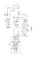
- Figure 3 is a schematic diagram of the electrical circuit of the hair dryer.
- Referring firstly to Figures 1 and 2, a hair dryer 10 for mounting on a surface such as a wall has a
moulded plastics casing 12. Thecasing 12 is provided at its top and bottom withflanges 14 and 16 in which are providedapertures casing 12 is anair intake 24 which is covered by acowl 26. Thecowl 26 overlaps theintake 24 and prevents water which is splashed onto thecasing 12 from entering the hair dryer 10, when, for instance, the hair dryer 10 is used in a bathroom. Also provided on the front of thecasing 12 are outlets 28 and 30 for use, for example, with electric shavers. - Attached to the
casing 12 near the bottom thereof is anair hose 32 of tough, heat resistant ABS (acrytonitrite-butadiene-styrene copolymer) plastics material. Thehose 32 terminates in ahandle 34 which has an air outlet 36 therein, through which heated air is exhausted when the hair dryer 10 is in operation. Thehandle 34 is mounted rotatably on the end of thehose 32. The air passage in thehandle 34 is defined by a tube (not shown) which connects the end of thehose 32 to the outlet 36. The air passage is sealed from the body of thehandle 34 and a layer of insulating material such as mica-impregnated sheeting or other insulating material insulates thehandle 34 thermally from the tube. This prevents thehandle 34 from becoming uncomfortably hot during use and permits the use of a heating element of higher rating than would otherwise be possible. - The part of the
handle 34 carrying the outlet 36 is shaped to fit in arecess 38 provided in thecasing 12. Magnets (not shown) in therecess 38 attract a metal grille which is fixed across the outlet 36 and thereby hold the handle firmly against thecasing 12 when the hair dryer 10 is not in use - The
casing 12 contains the active components of the hair dryer, including a motor and impeller assembly, a heater element with a thermostatic switch, a micro-switch, a transformer for supplying power to the outlets 28 and 30, and an electronic circuit for controlling the operation of the hair dryer 10. - Referring now to Figure 3, the electrical circuit of the hair dryer 10 is seen to comprise three basic sections. The first section includes the motor and heater element, the second section is a circuit for controlling the operation of the first section, and the third section is an independent circuit for supplying power to the outlets 28 and 30. All three sections are connected to the mains electrical supply.
- A
heater element 40 and its associatedthermostatic switch 42 are connected in series with amotor circuit 44, a micro-switch 46, and the contacts 48 of arelay 50. Themicro-switch 46 is arranged to be operated by an actuating button protruding into therecess 38 in thecasing 12, and is closed when thehandle 34 is removed from therecess 38, thereby connecting theheater element 40 and themotor circuit 44 to the electrical supply. The control circuit, comprising a 12volt transformer 52, arectifier bridge 54, atimer circuit 56 and therelay 50 are also connected to the supply. Thetimer circuit 56, which is a conventional electronic circuit assembled on a printed circuit board, immediately pulls in therelay 50, closing the normally open contacts 48. The circuit including theheater element 40 and themotor circuit 44 is thus completed and the hair dryer 10 operates, providing a stream of heated air via thehose 32 and the outlet 36. Thethermostatic switch 42 is mounted in close proximity to theheater element 40 and the normally closed contacts of theswitch 42 open if the temperature in the vicinity thereof is above a predetermined limit, for example if the outlet 36 should be blocked. After a predetermined time period has elapsed thetimer circuit 56 will de-activate therelay 50, even if thehandle 34 is not returned to its rest-position in therecess 38, thereby turning off the hair dryer 10. Normally, however, the user will replace thehandle 34 in therecess 38, thereby opening themicro-switch 46, turning off the hair dryer 10, and resetting thetimer circuit 56. - The
motor circuit 44 comprises aDC motor 58 connected between a bridge of four diodes 60, 62, 64 and 66. In series with themotor 58 and the bridge are twochokes 68 and 70, while acapacitor 72 and aresistor 74 are connected in parallel across the input to the bridge. Connected between the positive and negative leads of themotor 58 and a screen surrounding themotor 58 are two capacitors 76 and 78. Thediodes 60, 62, 64 and 66 rectify the current supplied to themotor 58, while thechokes 68 and 70, thecapacitor 72 and theresistor 74, and the capacitors 76 and 78 filter electrical noise generated by themotor 58. - Although the
motor 56 is a relatively low voltage DC motor (typically of 12 to 24 volt rating), the use of thediodes 60, 62, 64 and 66 permit it to be used on an AC supply. The relative voltage drops across the motor circuiit 44 and theheater element 40, which are connected in series and therefore form a voltage divider, are calculated so as to prevent the maximum rating of themotor 58 from being exceeded. - Independent of the above circuitry is a circuit for supplying the outlets 28 and 30 and comprising a centre- tapped
transformer 80, the primary winding of which is connected to the mains electrical supply in series with anoverload cutout 82. The secondary windings of the transformer are connected to the outlets 28 and 30, with one outlet being supplied with the normal mains voltage and the other being supplied with either half or double the mains voltage, depending on whether the nominal mains voltage is higher or lower than that required. For example, if the mains voltage is 220 V, one outlet will be supplied with 220 V, while the other will be supplied by one half of the centre- tapped secondary winding with 110 V. Thecutout 82 prevents more than a predetermined current, say 0,1A from being drawn from the sockets.
Claims (10)
Priority Applications (1)
| Application Number | Priority Date | Filing Date | Title |
|---|---|---|---|
| AT85305748T ATE36227T1 (en) | 1984-08-13 | 1985-08-13 | WALL MOUNTED HAIR DRYER. |
Applications Claiming Priority (2)
| Application Number | Priority Date | Filing Date | Title |
|---|---|---|---|
| ZA846270 | 1984-08-13 | ||
| ZA846270 | 1984-08-13 |
Publications (3)
| Publication Number | Publication Date |
|---|---|
| EP0172020A2 true EP0172020A2 (en) | 1986-02-19 |
| EP0172020A3 EP0172020A3 (en) | 1986-09-24 |
| EP0172020B1 EP0172020B1 (en) | 1988-08-10 |
Family
ID=25577465
Family Applications (1)
| Application Number | Title | Priority Date | Filing Date |
|---|---|---|---|
| EP85305748A Expired EP0172020B1 (en) | 1984-08-13 | 1985-08-13 | Wall-mounted hair dryer |
Country Status (4)
| Country | Link |
|---|---|
| US (1) | US4700049A (en) |
| EP (1) | EP0172020B1 (en) |
| AT (1) | ATE36227T1 (en) |
| DE (1) | DE3564180D1 (en) |
Cited By (5)
| Publication number | Priority date | Publication date | Assignee | Title |
|---|---|---|---|---|
| DE3904904A1 (en) * | 1988-02-19 | 1989-08-31 | Shivendra Varma | HAIR DRYER |
| US5404419A (en) * | 1993-06-25 | 1995-04-04 | Artis, Jr.; Amos | Wall-mounted cordless dryer for the hands with battery charging circuit, AM/FM radio, and vertical positioning means |
| KR200336373Y1 (en) * | 2003-06-16 | 2003-12-24 | 변정석 | Body Dryer With Hand Dryer |
| EP3366157A1 (en) * | 2017-02-24 | 2018-08-29 | Panasonic Intellectual Property Management Co., Ltd. | Handheld personal care device |
| FR3082694A1 (en) * | 2018-06-13 | 2019-12-20 | Atlantic Industrie | ELECTRIC HEATER COMPRISING AT LEAST ONE FEMALE ELECTRICAL OUTLET |
Families Citing this family (28)
| Publication number | Priority date | Publication date | Assignee | Title |
|---|---|---|---|---|
| DK173359B1 (en) * | 1988-02-04 | 2000-08-14 | Mo El Srl | Appliance for supplying hot air |
| US4873422A (en) * | 1988-05-05 | 1989-10-10 | Arvin Industries, Inc. | Wall mounted heater with plug mount and support |
| USD317514S (en) | 1988-11-04 | 1991-06-11 | Elite S.R.L. | Wall mounted hair dryer |
| DE69026477T2 (en) * | 1989-12-05 | 1996-11-28 | David Tabraham | Damper for clothes |
| USD345818S (en) | 1991-03-06 | 1994-04-05 | Aliseo Diffusion S.A. | Combined wall mounted hair dryer and mirror |
| USD353018S (en) | 1992-03-24 | 1994-11-29 | Aliseo Diffusion S.A. | Wall hair dryer |
| US5351417A (en) | 1992-09-22 | 1994-10-04 | Secajo, Ltd. | Hair dryer apparatus adapted for multi-functional usage |
| US5568691A (en) * | 1992-09-22 | 1996-10-29 | Secajo, Ltd. | Hair dryer apparatus adapted for multi-functional usage |
| US5438763A (en) * | 1994-11-29 | 1995-08-08 | Yang; Chiung-Hsiang | Multipurpose electric dryer |
| US5590475A (en) * | 1995-04-25 | 1997-01-07 | Andis Company | Hand held appliance and holder assembly |
| US5609047A (en) * | 1995-06-06 | 1997-03-11 | Nadia Wechsler | Garment steaming device with safety nozzle |
| US5823869A (en) * | 1997-08-22 | 1998-10-20 | Paturzo; Renato | Extendable air nozzle for use within a vehicle's interior |
| USD446349S1 (en) | 1998-04-02 | 2001-08-07 | Elite S.R.L. | Wall hung hair drier |
| AU5060599A (en) * | 1998-08-06 | 2000-02-28 | Castlegate Trading Limited | Control means for air emitting apparatus |
| USD451653S1 (en) | 2000-11-16 | 2001-12-04 | Sunbeam Products, Inc. | Clothes steamer |
| US6750747B2 (en) | 2002-08-29 | 2004-06-15 | Ljm Associates, Inc. | Proximity safety switch suitable for use in a hair dryer for disabling operation |
| US6784775B2 (en) * | 2002-08-29 | 2004-08-31 | Ljm Associates, Inc. | Proximity safety switch suitable for use in a hair dryer for disabling operation |
| FR2907642B1 (en) * | 2006-10-31 | 2009-01-23 | Seb Sa | HAIR DRYER COMPRISING A DISMANTABLE GRID |
| GB2467661B (en) | 2007-09-20 | 2013-02-13 | Bradley Fixtures Corp | Lavatory system |
| WO2011044247A1 (en) | 2009-10-07 | 2011-04-14 | Bradley Fixtures Corporation | Lavatory system with hand dryer |
| US9170148B2 (en) | 2011-04-18 | 2015-10-27 | Bradley Fixtures Corporation | Soap dispenser having fluid level sensor |
| US9267736B2 (en) | 2011-04-18 | 2016-02-23 | Bradley Fixtures Corporation | Hand dryer with point of ingress dependent air delay and filter sensor |
| CA2873015C (en) | 2012-03-21 | 2018-11-13 | Bradley Fixtures Corporation | Basin and hand drying system |
| US10100501B2 (en) | 2012-08-24 | 2018-10-16 | Bradley Fixtures Corporation | Multi-purpose hand washing station |
| US9982942B2 (en) * | 2014-02-10 | 2018-05-29 | World Dryer Corporation | Dryer with universal voltage controller |
| KR101601465B1 (en) * | 2014-08-13 | 2016-03-09 | 주식회사 아임 | Hair dryer |
| US10041236B2 (en) | 2016-06-08 | 2018-08-07 | Bradley Corporation | Multi-function fixture for a lavatory system |
| US11015329B2 (en) | 2016-06-08 | 2021-05-25 | Bradley Corporation | Lavatory drain system |
Citations (3)
| Publication number | Priority date | Publication date | Assignee | Title |
|---|---|---|---|---|
| FR2297387A1 (en) | 1975-01-10 | 1976-08-06 | Boccardi Carla | Wall mounted electric hair dryer - has hand piece retained in recess by magnets and actuating switch when removed |
| FR2395677A7 (en) | 1977-06-22 | 1979-01-19 | Handydryer Products Ltd | HAIR DRYER |
| US4366366A (en) | 1980-09-05 | 1982-12-28 | Ekblad Carl A | Electric iron stand with time delay safety switch arrangement |
Family Cites Families (13)
| Publication number | Priority date | Publication date | Assignee | Title |
|---|---|---|---|---|
| US1452085A (en) * | 1923-04-17 | Dental syringe | ||
| FR794827A (en) * | 1934-11-27 | 1936-02-26 | Automatic dryer | |
| GB487425A (en) * | 1937-01-28 | 1938-06-21 | Samuel Smith | Improvements in hair drying apparatus |
| US2646496A (en) * | 1951-01-10 | 1953-07-21 | Takach Sigmund | Combination speaker and heater for outdoor theaters |
| US2698894A (en) * | 1953-11-06 | 1955-01-04 | Stein Joseph | Electric hand and hair drier |
| US3076887A (en) * | 1959-12-30 | 1963-02-05 | Interstate Sanitation Company | Dryer |
| US3384977A (en) * | 1966-05-25 | 1968-05-28 | Rosenberg Raymond | Combined light fixture and blower |
| US3449838A (en) * | 1966-09-09 | 1969-06-17 | Chancellor Chair Co | Combination wall mounted dryer and heater |
| US4195416A (en) * | 1977-05-30 | 1980-04-01 | Hall Marshall J | Combination hair/hand/body dryer and vapor dispenser |
| US4276631A (en) * | 1978-04-03 | 1981-06-30 | Izumi Denki Corporation | Electronic timer |
| FR2478973A1 (en) * | 1980-03-26 | 1981-10-02 | Velecta Sa | Flexible hose attachment for hair-dryer - comprises two spaced coaxial corrugated tubes joined at their end by two rings |
| FR2492064B1 (en) * | 1980-10-09 | 1985-10-11 | Moulinex Sa | HOT AIR GENERATOR FOR HOUSEHOLD USE |
| US4493975A (en) * | 1982-09-30 | 1985-01-15 | Yamada Electric Industries Co., Ltd. | Hang-up hair dryer |
-
1985
- 1985-08-12 US US06/764,867 patent/US4700049A/en not_active Expired - Lifetime
- 1985-08-13 DE DE8585305748T patent/DE3564180D1/en not_active Expired
- 1985-08-13 EP EP85305748A patent/EP0172020B1/en not_active Expired
- 1985-08-13 AT AT85305748T patent/ATE36227T1/en not_active IP Right Cessation
Patent Citations (3)
| Publication number | Priority date | Publication date | Assignee | Title |
|---|---|---|---|---|
| FR2297387A1 (en) | 1975-01-10 | 1976-08-06 | Boccardi Carla | Wall mounted electric hair dryer - has hand piece retained in recess by magnets and actuating switch when removed |
| FR2395677A7 (en) | 1977-06-22 | 1979-01-19 | Handydryer Products Ltd | HAIR DRYER |
| US4366366A (en) | 1980-09-05 | 1982-12-28 | Ekblad Carl A | Electric iron stand with time delay safety switch arrangement |
Cited By (7)
| Publication number | Priority date | Publication date | Assignee | Title |
|---|---|---|---|---|
| DE3904904A1 (en) * | 1988-02-19 | 1989-08-31 | Shivendra Varma | HAIR DRYER |
| US5404419A (en) * | 1993-06-25 | 1995-04-04 | Artis, Jr.; Amos | Wall-mounted cordless dryer for the hands with battery charging circuit, AM/FM radio, and vertical positioning means |
| KR200336373Y1 (en) * | 2003-06-16 | 2003-12-24 | 변정석 | Body Dryer With Hand Dryer |
| EP3366157A1 (en) * | 2017-02-24 | 2018-08-29 | Panasonic Intellectual Property Management Co., Ltd. | Handheld personal care device |
| CN108501049A (en) * | 2017-02-24 | 2018-09-07 | 松下知识产权经营株式会社 | Handheld Personal Care Devices |
| US10543607B2 (en) | 2017-02-24 | 2020-01-28 | Panasonic Intellectual Property Management Co., Ltd. | Handheld personal care device |
| FR3082694A1 (en) * | 2018-06-13 | 2019-12-20 | Atlantic Industrie | ELECTRIC HEATER COMPRISING AT LEAST ONE FEMALE ELECTRICAL OUTLET |
Also Published As
| Publication number | Publication date |
|---|---|
| US4700049A (en) | 1987-10-13 |
| EP0172020B1 (en) | 1988-08-10 |
| ATE36227T1 (en) | 1988-08-15 |
| DE3564180D1 (en) | 1988-09-15 |
| EP0172020A3 (en) | 1986-09-24 |
Similar Documents
| Publication | Publication Date | Title |
|---|---|---|
| US4700049A (en) | Wall-mounted electric hair dryer incorporating dual-voltage electric shaver outlets | |
| US5146695A (en) | Hand or hair dryer | |
| US4347428A (en) | Handle and supporting structure for an electric pressing iron having electronic temperature control | |
| EP0784442B1 (en) | Apparatus adapted for multi-functional usage | |
| US5175791A (en) | Fragrance diffuser having stepped power levels | |
| KR100311649B1 (en) | Multipurpose Hair Dryer | |
| US5673360A (en) | Travel Humidifier | |
| EP0190080B1 (en) | Inhaler device | |
| GB2149985A (en) | Protection of electric hair dressing implements | |
| US6026590A (en) | Hair dryer with night light | |
| US3473859A (en) | Support structure for domestic appliance | |
| WO2004055847A1 (en) | Electrical device with a safety switch | |
| CA1210069A (en) | Electrical appliance with delayed warning alarm | |
| JP2557075B2 (en) | Electric iron | |
| JPH10257994A (en) | Hot air dryer | |
| EP0382521A1 (en) | Hand or hair dryer | |
| KR970003987Y1 (en) | A small iron combined with a hair dryer | |
| JPS6320885Y2 (en) | ||
| JPH0450875Y2 (en) | ||
| JP2578962B2 (en) | Digging kotatsu heater | |
| JPH0426545Y2 (en) | ||
| EP0342161A2 (en) | Apparatus to deliver hot air | |
| JPS58112587A (en) | Electronic control type iron | |
| JPH10248944A (en) | Infrared therapeutic apparatus | |
| MXPA97002440A (en) | Dryer apparatus for hair adapted for multifunction use |
Legal Events
| Date | Code | Title | Description |
|---|---|---|---|
| PUAI | Public reference made under article 153(3) epc to a published international application that has entered the european phase |
Free format text: ORIGINAL CODE: 0009012 |
|
| AK | Designated contracting states |
Kind code of ref document: A2 Designated state(s): AT BE CH DE FR GB IT LI LU NL SE |
|
| PUAL | Search report despatched |
Free format text: ORIGINAL CODE: 0009013 |
|
| AK | Designated contracting states |
Kind code of ref document: A3 Designated state(s): AT BE CH DE FR GB IT LI LU NL SE |
|
| 17P | Request for examination filed |
Effective date: 19870209 |
|
| 17Q | First examination report despatched |
Effective date: 19870601 |
|
| GRAA | (expected) grant |
Free format text: ORIGINAL CODE: 0009210 |
|
| AK | Designated contracting states |
Kind code of ref document: B1 Designated state(s): AT BE CH DE FR GB IT LI LU NL SE |
|
| REF | Corresponds to: |
Ref document number: 36227 Country of ref document: AT Date of ref document: 19880815 Kind code of ref document: T |
|
| REF | Corresponds to: |
Ref document number: 3564180 Country of ref document: DE Date of ref document: 19880915 |
|
| ITF | It: translation for a ep patent filed | ||
| ET | Fr: translation filed | ||
| PLBI | Opposition filed |
Free format text: ORIGINAL CODE: 0009260 |
|
| PLBI | Opposition filed |
Free format text: ORIGINAL CODE: 0009260 |
|
| 26 | Opposition filed |
Opponent name: HENDON INTERNATIONAL HOTEL & LEISURE PRODUCTS LIMI Effective date: 19890505 Opponent name: ELECTROSTAR SCHOETTLE GMBH & CO. Effective date: 19890505 Opponent name: ELITE S.R.L. Effective date: 19890505 |
|
| 26 | Opposition filed |
Opponent name: ALISEO DIFFUSION S.A. Effective date: 19890510 Opponent name: HENDON INTERNATIONAL HOTEL & LEISURE PRODUCTS LIMI Effective date: 19890505 Opponent name: ELECTROSTAR SCHOETTLE GMBH & CO. Effective date: 19890505 Opponent name: ELITE S.R.L. Effective date: 19890505 |
|
| NLR1 | Nl: opposition has been filed with the epo |
Opponent name: HENDON INTERNATIONAL HOTEL & LEISURE PRODUCTS LIM Opponent name: ELECTROSTAR SCHOETTLE GMBH & CO. Opponent name: ELITE S.R.L. |
|
| NLR1 | Nl: opposition has been filed with the epo |
Opponent name: ALISEO DIFFUSION S.A. |
|
| ITTA | It: last paid annual fee | ||
| PLAB | Opposition data, opponent's data or that of the opponent's representative modified |
Free format text: ORIGINAL CODE: 0009299OPPO |
|
| PLAB | Opposition data, opponent's data or that of the opponent's representative modified |
Free format text: ORIGINAL CODE: 0009299OPPO |
|
| R26 | Opposition filed (corrected) |
Opponent name: ELITE S.R.L. * 890505 ELECTROSTAR SCHOETTLE GMBH & Effective date: 19890505 |
|
| R26 | Opposition filed (corrected) |
Opponent name: ELITE S.R.L. * 890505 ELECTROSTAR SCHOETTLE GMBH & Effective date: 19890505 |
|
| NLXE | Nl: other communications concerning ep-patents (part 3 heading xe) |
Free format text: IN PAT.BUL.17/89,CORR.:HENDON INTERNATIONAL HOTEL & LEISURE PRODUCTS LIMITED/CHIIPS INC. |
|
| PGFP | Annual fee paid to national office [announced via postgrant information from national office to epo] |
Ref country code: GB Payment date: 19920812 Year of fee payment: 8 |
|
| PGFP | Annual fee paid to national office [announced via postgrant information from national office to epo] |
Ref country code: FR Payment date: 19920818 Year of fee payment: 8 |
|
| PGFP | Annual fee paid to national office [announced via postgrant information from national office to epo] |
Ref country code: SE Payment date: 19920820 Year of fee payment: 8 |
|
| PGFP | Annual fee paid to national office [announced via postgrant information from national office to epo] |
Ref country code: CH Payment date: 19920826 Year of fee payment: 8 |
|
| PGFP | Annual fee paid to national office [announced via postgrant information from national office to epo] |
Ref country code: NL Payment date: 19920831 Year of fee payment: 8 |
|
| PGFP | Annual fee paid to national office [announced via postgrant information from national office to epo] |
Ref country code: AT Payment date: 19920901 Year of fee payment: 8 |
|
| PGFP | Annual fee paid to national office [announced via postgrant information from national office to epo] |
Ref country code: DE Payment date: 19920909 Year of fee payment: 8 Ref country code: BE Payment date: 19920909 Year of fee payment: 8 |
|
| PGFP | Annual fee paid to national office [announced via postgrant information from national office to epo] |
Ref country code: LU Payment date: 19920914 Year of fee payment: 8 |
|
| EPTA | Lu: last paid annual fee | ||
| PG25 | Lapsed in a contracting state [announced via postgrant information from national office to epo] |
Ref country code: LU Free format text: LAPSE BECAUSE OF NON-PAYMENT OF DUE FEES Effective date: 19930813 Ref country code: GB Effective date: 19930813 Ref country code: AT Effective date: 19930813 |
|
| PG25 | Lapsed in a contracting state [announced via postgrant information from national office to epo] |
Ref country code: SE Effective date: 19930814 |
|
| PG25 | Lapsed in a contracting state [announced via postgrant information from national office to epo] |
Ref country code: LI Free format text: LAPSE BECAUSE OF NON-PAYMENT OF DUE FEES Effective date: 19930831 Ref country code: CH Free format text: LAPSE BECAUSE OF NON-PAYMENT OF DUE FEES Effective date: 19930831 Ref country code: BE Effective date: 19930831 |
|
| BERE | Be: lapsed |
Owner name: PANACHE PROMOTIONS LTD Effective date: 19930831 |
|
| PG25 | Lapsed in a contracting state [announced via postgrant information from national office to epo] |
Ref country code: NL Effective date: 19940301 |
|
| GBPC | Gb: european patent ceased through non-payment of renewal fee |
Effective date: 19930813 |
|
| NLV4 | Nl: lapsed or anulled due to non-payment of the annual fee | ||
| PG25 | Lapsed in a contracting state [announced via postgrant information from national office to epo] |
Ref country code: FR Effective date: 19940429 |
|
| REG | Reference to a national code |
Ref country code: CH Ref legal event code: PL |
|
| PG25 | Lapsed in a contracting state [announced via postgrant information from national office to epo] |
Ref country code: DE Effective date: 19940503 |
|
| REG | Reference to a national code |
Ref country code: FR Ref legal event code: ST |
|
| RDAG | Patent revoked |
Free format text: ORIGINAL CODE: 0009271 |
|
| STAA | Information on the status of an ep patent application or granted ep patent |
Free format text: STATUS: PATENT REVOKED |
|
| EUG | Se: european patent has lapsed |
Ref document number: 85305748.7 Effective date: 19940310 |
|
| 27W | Patent revoked |
Effective date: 19941219 |
|
| APAH | Appeal reference modified |
Free format text: ORIGINAL CODE: EPIDOSCREFNO |
|
| PLAB | Opposition data, opponent's data or that of the opponent's representative modified |
Free format text: ORIGINAL CODE: 0009299OPPO |
|
| PLAB | Opposition data, opponent's data or that of the opponent's representative modified |
Free format text: ORIGINAL CODE: 0009299OPPO |