EP0172024A2 - Steuereinrichtung für einen Laser - Google Patents
Steuereinrichtung für einen Laser Download PDFInfo
- Publication number
- EP0172024A2 EP0172024A2 EP85305766A EP85305766A EP0172024A2 EP 0172024 A2 EP0172024 A2 EP 0172024A2 EP 85305766 A EP85305766 A EP 85305766A EP 85305766 A EP85305766 A EP 85305766A EP 0172024 A2 EP0172024 A2 EP 0172024A2
- Authority
- EP
- European Patent Office
- Prior art keywords
- laser beam
- control signal
- laser
- disc
- sample
- Prior art date
- Legal status (The legal status is an assumption and is not a legal conclusion. Google has not performed a legal analysis and makes no representation as to the accuracy of the status listed.)
- Ceased
Links
Images


Classifications
-
- H—ELECTRICITY
- H01—ELECTRIC ELEMENTS
- H01S—DEVICES USING THE PROCESS OF LIGHT AMPLIFICATION BY STIMULATED EMISSION OF RADIATION [LASER] TO AMPLIFY OR GENERATE LIGHT; DEVICES USING STIMULATED EMISSION OF ELECTROMAGNETIC RADIATION IN WAVE RANGES OTHER THAN OPTICAL
- H01S3/00—Lasers, i.e. devices using stimulated emission of electromagnetic radiation in the infrared, visible or ultraviolet wave range
- H01S3/10—Controlling the intensity, frequency, phase, polarisation or direction of the emitted radiation, e.g. switching, gating, modulating or demodulating
- H01S3/13—Stabilisation of laser output parameters, e.g. frequency or amplitude
-
- G—PHYSICS
- G01—MEASURING; TESTING
- G01J—MEASUREMENT OF INTENSITY, VELOCITY, SPECTRAL CONTENT, POLARISATION, PHASE OR PULSE CHARACTERISTICS OF INFRARED, VISIBLE OR ULTRAVIOLET LIGHT; COLORIMETRY; RADIATION PYROMETRY
- G01J1/00—Photometry, e.g. photographic exposure meter
- G01J1/42—Photometry, e.g. photographic exposure meter using electric radiation detectors
- G01J1/4257—Photometry, e.g. photographic exposure meter using electric radiation detectors applied to monitoring the characteristics of a beam, e.g. laser beam, headlamp beam
-
- G—PHYSICS
- G02—OPTICS
- G02B—OPTICAL ELEMENTS, SYSTEMS OR APPARATUS
- G02B26/00—Optical devices or arrangements for the control of light using movable or deformable optical elements
- G02B26/02—Optical devices or arrangements for the control of light using movable or deformable optical elements for controlling the intensity of light
- G02B26/04—Optical devices or arrangements for the control of light using movable or deformable optical elements for controlling the intensity of light by periodically varying the intensity of light, e.g. using choppers
-
- G—PHYSICS
- G02—OPTICS
- G02B—OPTICAL ELEMENTS, SYSTEMS OR APPARATUS
- G02B26/00—Optical devices or arrangements for the control of light using movable or deformable optical elements
- G02B26/08—Optical devices or arrangements for the control of light using movable or deformable optical elements for controlling the direction of light
- G02B26/0875—Optical devices or arrangements for the control of light using movable or deformable optical elements for controlling the direction of light by means of one or more refracting elements
- G02B26/0883—Optical devices or arrangements for the control of light using movable or deformable optical elements for controlling the direction of light by means of one or more refracting elements the refracting element being a prism
- G02B26/0891—Optical devices or arrangements for the control of light using movable or deformable optical elements for controlling the direction of light by means of one or more refracting elements the refracting element being a prism forming an optical wedge
Definitions
- the present invention relates to the control of the- quality of a laser beam.
- Lasers are becoming used more and more in industry in circumstances where it is of the greatest importance that the maximum use is made of the power which is available, nominally, from the laser. To do this it is necessary to monitor continuously the laser beam quality, and alter the operating parameters of the laser to maximise the usable power in the laser beam.
- an apparatus for monitoring and controlling a beam of radiation from a laser comprising means for directing at least a portion of the laser beam at a means for determining the transverse distribution of energy within the laser beam under near field conditions and producing a first control signal related thereto, means for directing a second portion of the laser beam at a means for determining the transverse distribution of energy within the laser beam under far field conditions and producing a second control signal related thereto, and means for directing a known proportion of the laser beam at a means for measuring the total power within the said proportion of the laser beam and producing a third control signal related thereto, means responsive to the first control signal to alter the position of a mirror which forms part of an optical cavity within the laser structure, means responsive to the first and second control signals, to direct the laser beam along a predetermined path, means responsive to the second control signal to maintain the divergence of the laser beam within predetermined limits, and means responsive to the third control signal to vary the amount of power supplied to the laser.
- Figure 1 shows schematically the optical arrangement of a laser beam diagnostic system.
- a laser beam 1 from a laser L is diverted by an input mirror 2 to a beam expander mirror 3 via a safety isolator 4.
- the beam expander mirror 3 reflects the laser beam 1 to a second beam expander mirror 5.
- the beam expander mirror 5 reflects the laser beam 1 to a partially transmitting mirror 6, whence the major part is reflected to an output mirror 7 via an output shutter 8, and thence to a work station, which is not shown.
- the beam expander mirror 3 has a rectangular matrix of bales formed in it, so that in effect the laser beam 1 is sampled spatially.
- Light passing through the beam expander mirror 3 passes through an imaging lens 9 to a beam folding mirror 10 and a switching mirror 11.
- the switching mirror 11 directs the laser beam sample 1' to a sheet of plastic 12, upon which it is brought to a focus and produces a burn pattern corresponding to the distribution of energy in the original laser beam 1.
- the switching mirror 11 directs the laser beam sample 1' to a far field monitor 13, to be described later.
- the portion 1" of the laser beam 1 which is transmitted by the mirror 6 is directed by a series of mirrors 14, one of which 14', is partially reflecting only, to a near field monitor 15, and a power monitor 16, both of which will be described later.
- the far field monitor 13 and near field monitor 15 have their operating sequences, data aquisition, storage, processing and display controlled by a microprocessor based system 17 which also generates control signals for a drive system 18 for a mirror (not shown) which form of part of the optical cavity of the laser, and a laser power supply 19 and pointing mirror drive 20.
- the far field monitor 15 consists of a pair of optical wedges 21 and 22 which are arranged to rotate around a common axis.
- the angle of the wedge 21 is less than that of the wedge 22.
- Their apices lie in the same plane but on opposite sides of their axis of rotation.
- the wedge 21 also can be moved axially with respect to the wedge 22.
- a detector plane 23 has a hole 24 some 20wm in diameter centred on the axis of rotation of the wedges 21 and 22. Behind the detector plane 23 is a pyroelectric detector 25. Initially the wedges 21 and 22 are positioned so that the sampled laser beam 1' is stationary and centred on the hole 24 in the detector plane 23.
- the wedges 21 and 22 are set in motion, the wedge 21 being reciprocated axially with respect to the wedge 22, as well as being rotated. As the wedge 21 moves away from the wedge 22, the sampled laser beam 1' is caused to travel in a spiral path around the hole 24, in turn causing the sampled beam 1' effectively to travel in a spiral path on the cross-section of the sampled laser beam 1'.
- the output from the detector 25 is digitised at regular intervals by the microprocessor system 17 so as to produce 16 digitised beam samples along each of 18 radii.
- Quantitative analysis of the output of the detector 25 gives graphical displays such as those shown in Figure 3.
- the display 3(a) is self explanatory.
- the radial plot 3(b) is a series of intensity profiles across each of the nine diameters contained in the spiral scan of the sampled laser beam 1'. This form of display clearly shows the diffraction rings and their intensity relative to the central peak, the position of the centre of the sampled laser beam 1 1 , and hence the main laser beam 1, and any variations in the axial symmetry of the laser beam 1.
- the power characteristic display 3(c) shows the enclosed power as a function of the radius. Two other parameters also are displayed. One is the maximum intensity of the central peak, which is indicated by the pointer on the left ordinate axis; the other is the power enclosed by the maximum radius, which is indicate by the position of the pointer on the right hand ordinate axis.
- the near field monitor consists of a radius disc assembly 40 centred on the portion 1" of the laser beam 1 transmitted by the mirror 6.
- the radius disc assembly 40 includes a radius disc 41 which has a radial slit 42 in it which defines a radius of the input aperture of the near field monitor 15.
- a fiduciary mark 43 On the periphery of the radius disc 41 there is a fiduciary mark 43 and a sensor 44 which sense the beginning of each scan of the beam 1" as the radius disc 41 is rotated.
- Mounted on the radius disc 41 is a scanning slit 45 which has six regularly spaced radial slits 46 and is arranged to rotate at three times the rate of the radius disc 41.
- the combined motion of the two discs 41 and 45 causes an aperture to pass sequentially along 18 regularly spaced radii of the entrance aperture of the near field monitor 15 for each rotation of the radius disc assembly 40.
- Any part of the beam 1" passing through the aperture produced by the movement of the combined slits 42 and 46 is directed by a lens 47 to a detector 48.
- a chopper wheel 49 is placed in front of the detector 48 and is arranged to rotate at such a rate in relation to the rotation of the radius disc assembly 40 that 16 samples along each radial sample are produced by that assembly.
- the output from the near field monitor 15 also is digitised and processed by the microprocessor system 17.
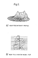
- a typical three-dimensional plot of the output from the near field monitor 15 is shown in Figure 5(a).
- Figure 5(b) shows corresponding radial plots, two of which, approximately orthogonal to each other, are emphasised.
- Quantitative analysis of the output information from the near field monitor 15 gives the diameter of the beam 1", and hence the unfocussed laser beam 1, and its position in relation to the polar scanning matrix of the radius disc assembly 40.
- a control signal derived from this data by the microprocessor system 17 is used to alter the position of the input mirror 2.
- the fraction 1111 of the laser beam 1 which is transmitted by the partially reflecting mirrors 6 and 14' is reduced in diameter by the final mirror 14 before entering the power monitor 16.
- the first is a 100 watt power meter disc
- the second a pyroelectric detector having a removable polarising element or grid polariser and arranged to monitor transients or oscillations in the intensity of the laser beam to a frequency of 100 kH z .
- the third detector is arranged to monitor mode beating to a frequency of 60 MH z .
- the outputs from the second and third detectors are displayed on an oscilloscope or processed by a frequency analyser within the microprocessor unit 17.
- the output from the first detector is used to provide a control signal which is applied to a laser power supply system 19.
- One application of the invention is in the continuous monitoring of a laser beam used in cutting and welding operations in a nuclear fuel reprocessing plant, for example in a fast reactor fuel reprocessing plant.
- the laser beam might be used for cutting through a portion of a wall of a transport canister containing a fast reactor fuel sub assembly, and subsequently dismantling the sub assembly by selected cuts of a wrapper about the sub assembly. It is essential that a closely controlled laser beam be used, particularly for the sub assembly dismantling, with the automatic control of the laser beam by use of a feedback circuit from the monitor, for example to control the power level of the laser beam.
Landscapes
- Physics & Mathematics (AREA)
- Optics & Photonics (AREA)
- General Physics & Mathematics (AREA)
- Electromagnetism (AREA)
- Spectroscopy & Molecular Physics (AREA)
- Engineering & Computer Science (AREA)
- Plasma & Fusion (AREA)
- Lasers (AREA)
- Photometry And Measurement Of Optical Pulse Characteristics (AREA)
- Testing Of Optical Devices Or Fibers (AREA)
- Laser Beam Processing (AREA)
Applications Claiming Priority (2)
| Application Number | Priority Date | Filing Date | Title |
|---|---|---|---|
| GB8420861 | 1984-08-16 | ||
| GB848420861A GB8420861D0 (en) | 1984-08-16 | 1984-08-16 | Laser control system |
Publications (2)
| Publication Number | Publication Date |
|---|---|
| EP0172024A2 true EP0172024A2 (de) | 1986-02-19 |
| EP0172024A3 EP0172024A3 (de) | 1988-01-27 |
Family
ID=10565431
Family Applications (1)
| Application Number | Title | Priority Date | Filing Date |
|---|---|---|---|
| EP85305766A Ceased EP0172024A3 (de) | 1984-08-16 | 1985-08-14 | Steuereinrichtung für einen Laser |
Country Status (4)
| Country | Link |
|---|---|
| US (1) | US4707836A (de) |
| EP (1) | EP0172024A3 (de) |
| JP (1) | JPS61116890A (de) |
| GB (1) | GB8420861D0 (de) |
Cited By (3)
| Publication number | Priority date | Publication date | Assignee | Title |
|---|---|---|---|---|
| EP0319345A3 (de) * | 1987-12-03 | 1990-08-16 | Westinghouse Electric Corporation | Vorrichtung zur Abbildung der Intensitätsverteilung in einem Hochleistungs-Laserstrahl |
| FR2736762A1 (fr) * | 1995-07-11 | 1997-01-17 | Thomson Csf | Systeme de controle de faisceau laser |
| DE10223319A1 (de) * | 2002-05-24 | 2003-12-04 | Zeiss Carl Laser Optics Gmbh | Optisches Abbildungssystem zum Abbilden zumindest zweier in Strahlrichtung beabstandeter Ebenen eines Lichtstrahls |
Families Citing this family (8)
| Publication number | Priority date | Publication date | Assignee | Title |
|---|---|---|---|---|
| WO2001059414A1 (en) * | 2000-02-09 | 2001-08-16 | Lambda Physik Ag | Vuv laser beam characterization system |
| US6624424B2 (en) * | 2000-02-09 | 2003-09-23 | Lambda Physik Ag | VUV laser beam characterization system |
| DE10033071A1 (de) * | 2000-07-07 | 2002-01-17 | Trumpf Lasertechnik Gmbh | Laseranordnung für die Materialbearbeitung |
| US6339608B1 (en) | 2000-10-18 | 2002-01-15 | The Regents Of The University Of California | Method for beam steering compensation in an ultra-high power liquid laser |
| US10072971B2 (en) | 2010-04-16 | 2018-09-11 | Metal Improvement Company, Llc | Flexible beam delivery system for high power laser systems |
| DE102012212354B4 (de) * | 2012-07-13 | 2024-05-16 | Asml Netherlands B.V. | Messvorrichtung zur Vermessung und Überwachung mindestens eines Laserstrahls, Strahlführungssystem zur Führung mindestens eines Laserstrahls mit einer derartigen Messvorrichtung sowie Verwendung einer derartigen Messvorrichtung |
| US9976947B1 (en) * | 2014-11-24 | 2018-05-22 | TVS Holdings, LLC | Position measurement device |
| CN107884389A (zh) | 2017-12-26 | 2018-04-06 | 同方威视技术股份有限公司 | 拉曼光谱检测设备和方法 |
Family Cites Families (9)
| Publication number | Priority date | Publication date | Assignee | Title |
|---|---|---|---|---|
| US3746429A (en) * | 1971-08-05 | 1973-07-17 | Recognition Systems | Linear variable light attenuator |
| US4018535A (en) * | 1975-10-28 | 1977-04-19 | The United States Of America As Represented By The Secretary Of The Army | Device for measuring energy transfer rates during lasing |
| US4008444A (en) * | 1976-01-19 | 1977-02-15 | Avco Everett Research Laboratory, Inc. | Feedback control of a laser output |
| US4144505A (en) * | 1977-10-25 | 1979-03-13 | The United States Of America As Represented By The Secretary Of The Navy | Autoalignment system for laser with unstable resonator |
| US4272734A (en) * | 1979-05-29 | 1981-06-09 | Spectra-Physics, Inc. | Dual reference interferometer for dye laser stabilization |
| US4260225A (en) * | 1979-06-18 | 1981-04-07 | The Dow Chemical Company | Energy saving radiant insulative device |
| DE2939697A1 (de) * | 1979-09-29 | 1981-04-16 | Kabel- und Metallwerke Gutehoffnungshütte AG, 3000 Hannover | Richtantenne |
| US4329659A (en) * | 1979-12-27 | 1982-05-11 | Bell Telephone Laboratories, Incorporated | Feedback control of lasers in fiber optic systems |
| US4344707A (en) * | 1980-05-14 | 1982-08-17 | Rockwell International Corporation | Modal sensor |
-
1984
- 1984-08-16 GB GB848420861A patent/GB8420861D0/en active Pending
-
1985
- 1985-08-12 US US06/764,643 patent/US4707836A/en not_active Expired - Fee Related
- 1985-08-14 EP EP85305766A patent/EP0172024A3/de not_active Ceased
- 1985-08-15 JP JP60180003A patent/JPS61116890A/ja active Pending
Cited By (5)
| Publication number | Priority date | Publication date | Assignee | Title |
|---|---|---|---|---|
| EP0319345A3 (de) * | 1987-12-03 | 1990-08-16 | Westinghouse Electric Corporation | Vorrichtung zur Abbildung der Intensitätsverteilung in einem Hochleistungs-Laserstrahl |
| FR2736762A1 (fr) * | 1995-07-11 | 1997-01-17 | Thomson Csf | Systeme de controle de faisceau laser |
| DE10223319A1 (de) * | 2002-05-24 | 2003-12-04 | Zeiss Carl Laser Optics Gmbh | Optisches Abbildungssystem zum Abbilden zumindest zweier in Strahlrichtung beabstandeter Ebenen eines Lichtstrahls |
| DE10223319B4 (de) * | 2002-05-24 | 2004-04-01 | Carl Zeiss Laser Optics Gmbh | Optisches Abbildungssystem zum Abbilden zumindest zweier in Strahlrichtung beabstandeter Ebenen eines Lichtstrahls |
| US7477438B2 (en) | 2002-05-24 | 2009-01-13 | Carl Zeiss Laser Optics Gmbh | Optical imaging system for imaging at least two planes of a light beam spaced apart in the beam direction |
Also Published As
| Publication number | Publication date |
|---|---|
| US4707836A (en) | 1987-11-17 |
| GB8420861D0 (en) | 1984-09-19 |
| EP0172024A3 (de) | 1988-01-27 |
| JPS61116890A (ja) | 1986-06-04 |
Similar Documents
| Publication | Publication Date | Title |
|---|---|---|
| US4707836A (en) | Laser control system | |
| US4828384A (en) | High power laser beam intensity mapping apparatus | |
| DE69115914T2 (de) | Interferenzmikroskop | |
| EP0022263B1 (de) | Lichtvorhangvorrichtung mit Mitteln zur Erzeugung zyklisch wechselnden Massstabsignals | |
| EP0067554B1 (de) | Messung der Teilchengrösse | |
| EP0352133A2 (de) | Optisches Polarimeter | |
| EP0412581A2 (de) | Gerät zum Kontrollieren des Fokuszustands eines Aufzeichnungslichtstrahls | |
| US4319839A (en) | Beam alignment system | |
| JPH07501397A (ja) | 測定方法および装置 | |
| EP0129150A2 (de) | Verfahren zur berührungslosen, emissionsgradunabhängigen Strahlungsmessung der Temperatur eines Objekts und Vorrichtung zur Durchführung der Verfahren | |
| US4777341A (en) | Back reflection monitor and method | |
| US3586865A (en) | Method of,and apparatus for,inspecting the shape of small objects | |
| US3675016A (en) | Flying spot scanning | |
| US5909274A (en) | Device for the characterization of laser beams | |
| US4848902A (en) | Device for measuring the intensity profile of a laser beam | |
| EP4035818A1 (de) | Verfahren und vorrichtung zur laserbearbeitungsüberwachung | |
| Lim et al. | Instrument for instantaneous in situ analysis of the mode structure of a high-power laser beam | |
| JPH06106378A (ja) | レーザ加工装置 | |
| US4054388A (en) | Optical control means | |
| EP0236008A1 (de) | Überwachung eines Laserstrahlenbündels | |
| Scaggs et al. | Real-time monitoring of thermal lensing of a multikilowatt fiber laser optical system | |
| US4941733A (en) | Optical correlator system | |
| Suzaki et al. | Measurement of the Gaussian laser beam divergence | |
| US3250174A (en) | Method and apparatus for comparing radiation in one spectral region with radiation in another spectral region | |
| US4676597A (en) | Imaging monochromator |
Legal Events
| Date | Code | Title | Description |
|---|---|---|---|
| PUAI | Public reference made under article 153(3) epc to a published international application that has entered the european phase |
Free format text: ORIGINAL CODE: 0009012 |
|
| AK | Designated contracting states |
Designated state(s): DE FR GB |
|
| PUAL | Search report despatched |
Free format text: ORIGINAL CODE: 0009013 |
|
| AK | Designated contracting states |
Kind code of ref document: A3 Designated state(s): DE FR GB |
|
| 17P | Request for examination filed |
Effective date: 19880722 |
|
| 17Q | First examination report despatched |
Effective date: 19910603 |
|
| STAA | Information on the status of an ep patent application or granted ep patent |
Free format text: STATUS: THE APPLICATION HAS BEEN REFUSED |
|
| 18R | Application refused |
Effective date: 19911205 |
|
| RIN1 | Information on inventor provided before grant (corrected) |
Inventor name: TRAVIS, ALAN JOHN BASIL |