EP0172043A1 - Ensemble de bobines d'inducteur de machine electrique tournante - Google Patents
Ensemble de bobines d'inducteur de machine electrique tournante Download PDFInfo
- Publication number
- EP0172043A1 EP0172043A1 EP85401164A EP85401164A EP0172043A1 EP 0172043 A1 EP0172043 A1 EP 0172043A1 EP 85401164 A EP85401164 A EP 85401164A EP 85401164 A EP85401164 A EP 85401164A EP 0172043 A1 EP0172043 A1 EP 0172043A1
- Authority
- EP
- European Patent Office
- Prior art keywords
- coils
- turns
- assembly
- coil
- assembly according
- Prior art date
- Legal status (The legal status is an assumption and is not a legal conclusion. Google has not performed a legal analysis and makes no representation as to the accuracy of the status listed.)
- Granted
Links
Images
Classifications
-
- H—ELECTRICITY
- H02—GENERATION; CONVERSION OR DISTRIBUTION OF ELECTRIC POWER
- H02K—DYNAMO-ELECTRIC MACHINES
- H02K15/00—Processes or apparatus specially adapted for manufacturing, assembling, maintaining or repairing of dynamo-electric machines
- H02K15/04—Processes or apparatus specially adapted for manufacturing, assembling, maintaining or repairing of dynamo-electric machines of windings prior to their mounting into the machines
- H02K15/043—Processes or apparatus specially adapted for manufacturing, assembling, maintaining or repairing of dynamo-electric machines of windings prior to their mounting into the machines winding flat conductive wires or sheets
-
- H—ELECTRICITY
- H02—GENERATION; CONVERSION OR DISTRIBUTION OF ELECTRIC POWER
- H02K—DYNAMO-ELECTRIC MACHINES
- H02K3/00—Details of windings
- H02K3/04—Windings characterised by the conductor shape, form or construction, e.g. with bar conductors
- H02K3/18—Windings for salient poles
Definitions
- the present invention relates to a set of inductor coils of a rotating electrical machine, in particular for a motor vehicle starter.
- the inductors of such starters generally consist of coils of a shape suitable for the dimensions of the polar masses, and whose turns of conductors in flat wire are insulated from each other by a paper insulator, or the like, and held together by an adhesive tape.
- the coils thus obtained are then shaped to conform to the internal shape of the machine carcass around the polar masses, then immersed in a plasticizing bath which, after polymerization, ensures the final maintenance.
- the object of the present invention is to remedy these drawbacks and to this end relates to a set of inductor coils of a rotating electric machine, in particular for motor vehicle starter, each coil of which is produced from a conductive strip wound in coils maintained stationary with respect to each other by mechanical means, assembly characterized in that the end of the inner turn of at least one of the coils is arched in the shape of a stirrup in which is clamped all the turns constituting the coil.
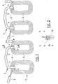
- the inductor assembly 1 represented in FIG. 1 is made up in a known manner of four coils 3 connected to each other which are produced between them which are produced from a strip of conductive metal wound in turns separated by insulators and kept stationary the relative to each other by mechanical means.
- the conductive strip preferably has a cross section such that after winding, the turns forming the coils fit into one another and can be in particular in the form of a chevron, as shown in FIG. 2, or in the form of 'arc of circle or trigger guard as in the patent application FR. 78.04345.
- the end of the inner turn 11 of the coil 3, shown in FIG. 2 is arched in the shape of a stirrup 6 which keeps the turns stationary between them by their pinching between the branhes 9 and 10 of the stirrup 6, the central part of which is pressed against one of the edges 3a of the turns, and the branches 9 and 10 of which are shaped on the outer chevron shape of the conductive strip.
- the two pairs of coils 2 are identical and their free ends 7 and 8 are arched and directed flat so as to facilitate the electrical junction of the end free 7 of one of the pairs of coils 2 with the free end 8 of the other pair of coils.
- Such an assembly is then shaped by bending and immersed in a plasticizing bath in a known manner.
Landscapes
- Engineering & Computer Science (AREA)
- Power Engineering (AREA)
- Manufacturing & Machinery (AREA)
- Windings For Motors And Generators (AREA)
- Manufacture Of Motors, Generators (AREA)
- Insulation, Fastening Of Motor, Generator Windings (AREA)
Abstract
Description
- La présente invention concerne un ensemble de bobines d'inducteur de machine électrique tournante notamment pour démarreur de véhicule automobile.
- Les inducteurs de tels démarreurs sont constitués généralement de bobines de forme appropriée aux dimensions des masses polaires, et dont les spires de conducteurs en fil plat sont isolées entre elles par un isolant papier, ou autre, et maintenue ensemble par un ruban adhésif. Les bobines ainsi obtenues sont ensuite conformées pour épouser la forme intérieure de la carcasse de la machine autour des masses polaires, puis immergées dans un bain plastifiant qui, après polymérisation assure le maintien définitif.
- Il en résulte parfois une rupture du ruban adhésif lors du cambrage des bobines et conséquemment une augmentation notable de l'encombrement desdites bobines. Il devient alors impossible d'effectuer l'assemblage de l'ensemble du démarrreur.
- Il est connu dans la demande de brevet n° 7924584 un procédé d'immobilisation des spires formant les bobines qui consiste à poser le ruban adhésif sur les bobines préalablement cambrées suivant la forme de leur support, l'ensemble étant ensuite plongé dans un bain plastifiant. Bien que ce procédé donne des résultats satisfaisants il nécessite une mise en oeuvre importante et conséquemment entraîne un prix de revient élevé.
- La présente invention a pour but de remédier à ces inconvénients et concerne à cet effet un ensemble de bobines d'inducteur de machine électrique tournante, notamment pour démarreur de véhicules automobiles dont chaque bobine est réalisée à partir d'une bande conductrice enroulée en spires maintenues immobiles les unes par rapport aux autres par des des moyens mécaniques, ensemble caractérisé en ce que l'extrémité de la spire intérieure d'au moins une des bobines est cambrée en forme d'étrier dans lequel est pincé l'ensemble des spires constitutives de la bobine.
- La description qui va suivre en regard des figures annexées fera mieux comprendre comment l'invention peut être réalisée.
- La figure 1 représente en plan un ensemble de bobines d'inducteur conforme à l'invention.
- La figure 2 représente, suivant la coupe II II de la figure 1, le maintien des spires de bobines par un étrier de pincement.
- L'ensemble inducteur 1 représenté à la figure 1 est constitué de façon connue de quatre bobines 3 reliées entre elles qui sont réalisées entre elles qui sont réalisées à partir d'une bande de métal conducteur enroulée en spires séparées par des isolants et maintenues immobiles les unes par rapport aux autres par des moyens mécaniques.
- La bande conductrice présente de préférence une section droite telle qu'après bobinage, les spires formant les bobines s'encastrent les unes dans les autres et peut se présenter notamment sous forme de chevron, tel que représenté à la figure 2, ou sous forme d'arc de cercle ou de pontet tel que dans la demande de brevet FR. 78.04345.
- Conformément à l'invention l'extrémité de la spire intérieure 11de la bobine 3, représentée à la figure 2 est cambrée en forme d'étrier 6 qui maintient immobiles les spires entre elles par leur pincement entre les branhes 9 et 10 de l'étrier 6 dont la partie centrale est plaquée contre une des tranches3a des spires, et dont les branches 9 et 10 sont conformées sur la forme extérieure en chevron de la bande conductrice.
- Deux bobines 3 consécutives sont avantageusement maintenues entre elles par un pontet 5 qui relie les étriers 6 des bobines. Ce pontet est réalisé de matière avec la paire de bobines 2 ainsi obtenue.
- Afin de faciliter la liaison de deux paires de bobines 2 pour former un ensemble inducteur 1, les deux paires de bbbines 2 sont identiques et leurs extrémités libres 7 et 8 sont cambrées et dirigées à plat de façon à faciliter la jonction électrique de l'extrémité libre 7 d'une des paires de bobines 2 avec l'extrémité libre 8 de l'autre paire de bobines.
- Un tel ensemble est alors mis en forme par cambrage et plongé dans un bain plastifiant de façon connue.
Claims (5)
Applications Claiming Priority (2)
| Application Number | Priority Date | Filing Date | Title |
|---|---|---|---|
| FR8411844A FR2568426B1 (fr) | 1984-07-26 | 1984-07-26 | Ensemble de bobines d'inducteur de machine electrique tournante. |
| FR8411844 | 1984-07-26 |
Publications (2)
| Publication Number | Publication Date |
|---|---|
| EP0172043A1 true EP0172043A1 (fr) | 1986-02-19 |
| EP0172043B1 EP0172043B1 (fr) | 1988-05-18 |
Family
ID=9306510
Family Applications (1)
| Application Number | Title | Priority Date | Filing Date |
|---|---|---|---|
| EP85401164A Expired EP0172043B1 (fr) | 1984-07-26 | 1985-06-13 | Ensemble de bobines d'inducteur de machine electrique tournante |
Country Status (4)
| Country | Link |
|---|---|
| EP (1) | EP0172043B1 (fr) |
| DE (1) | DE3562848D1 (fr) |
| ES (1) | ES295872Y (fr) |
| FR (1) | FR2568426B1 (fr) |
Cited By (3)
| Publication number | Priority date | Publication date | Assignee | Title |
|---|---|---|---|---|
| EP0371933A1 (fr) * | 1988-11-30 | 1990-06-06 | INDUSTRIE MAGNETI MARELLI S.p.A. | Méthode de fabrication d'un enroulement pour le stator d'une machine électrique à courant continu |
| FR2644304A1 (fr) * | 1989-03-08 | 1990-09-14 | Le Proizv | Rotor de machine electrique avec enroulement d'excitation supraconducteur |
| WO1992002982A1 (fr) * | 1990-08-08 | 1992-02-20 | Zahnradfabrik Friedrichshafen Ag | Moteur a champ magnetique rotatif |
Citations (6)
| Publication number | Priority date | Publication date | Assignee | Title |
|---|---|---|---|---|
| AT124543B (de) * | 1926-07-16 | 1931-09-25 | Vormals Skodawerke Ag | Permutierter Leiter für elektrische Maschinen und Apparate. |
| FR1198390A (fr) * | 1957-08-10 | 1959-12-07 | Bosch Gmbh Robert | Bobine pour enroulements électriques et notamment bobine d'excitation pour machinesà courant continu basse tension |
| GB877762A (en) * | 1957-10-04 | 1961-09-20 | English Electric Co Ltd | Improvements relating to wound magnetic core structures |
| FR1317071A (fr) * | 1962-03-08 | 1963-02-01 | Cav Ltd | Machine électrodynamique |
| US3452230A (en) * | 1967-12-15 | 1969-06-24 | Gen Electric | Electromagnetic coil structure for dynamoelectric machine stators |
| FR2417878A1 (fr) * | 1978-02-16 | 1979-09-14 | Ducellier & Cie | Bobine et inducteur a fil plat de machine electrique tournante |
Family Cites Families (1)
| Publication number | Priority date | Publication date | Assignee | Title |
|---|---|---|---|---|
| DE410043C (de) * | 1921-10-18 | 1925-02-23 | H Cuenod S A Atel | Induktionsmotor |
-
1984
- 1984-07-26 FR FR8411844A patent/FR2568426B1/fr not_active Expired
-
1985
- 1985-06-13 DE DE8585401164T patent/DE3562848D1/de not_active Expired
- 1985-06-13 EP EP85401164A patent/EP0172043B1/fr not_active Expired
- 1985-07-24 ES ES1985295872U patent/ES295872Y/es not_active Expired
Patent Citations (6)
| Publication number | Priority date | Publication date | Assignee | Title |
|---|---|---|---|---|
| AT124543B (de) * | 1926-07-16 | 1931-09-25 | Vormals Skodawerke Ag | Permutierter Leiter für elektrische Maschinen und Apparate. |
| FR1198390A (fr) * | 1957-08-10 | 1959-12-07 | Bosch Gmbh Robert | Bobine pour enroulements électriques et notamment bobine d'excitation pour machinesà courant continu basse tension |
| GB877762A (en) * | 1957-10-04 | 1961-09-20 | English Electric Co Ltd | Improvements relating to wound magnetic core structures |
| FR1317071A (fr) * | 1962-03-08 | 1963-02-01 | Cav Ltd | Machine électrodynamique |
| US3452230A (en) * | 1967-12-15 | 1969-06-24 | Gen Electric | Electromagnetic coil structure for dynamoelectric machine stators |
| FR2417878A1 (fr) * | 1978-02-16 | 1979-09-14 | Ducellier & Cie | Bobine et inducteur a fil plat de machine electrique tournante |
Cited By (3)
| Publication number | Priority date | Publication date | Assignee | Title |
|---|---|---|---|---|
| EP0371933A1 (fr) * | 1988-11-30 | 1990-06-06 | INDUSTRIE MAGNETI MARELLI S.p.A. | Méthode de fabrication d'un enroulement pour le stator d'une machine électrique à courant continu |
| FR2644304A1 (fr) * | 1989-03-08 | 1990-09-14 | Le Proizv | Rotor de machine electrique avec enroulement d'excitation supraconducteur |
| WO1992002982A1 (fr) * | 1990-08-08 | 1992-02-20 | Zahnradfabrik Friedrichshafen Ag | Moteur a champ magnetique rotatif |
Also Published As
| Publication number | Publication date |
|---|---|
| EP0172043B1 (fr) | 1988-05-18 |
| FR2568426A1 (fr) | 1986-01-31 |
| ES295872U (es) | 1987-06-16 |
| FR2568426B1 (fr) | 1988-11-18 |
| ES295872Y (es) | 1987-12-16 |
| DE3562848D1 (en) | 1988-06-23 |
Similar Documents
| Publication | Publication Date | Title |
|---|---|---|
| US4446393A (en) | Dynamoelectric field assembly and winding therefor | |
| US10032544B2 (en) | Terminal treatment apparatus for a coaxial cable to separate a sheath from a conductor | |
| US9240662B2 (en) | Terminal treatment method and terminal treatment apparatus for coaxial cable | |
| JPH05328674A (ja) | 電機子及び電機子の巻線の接続方法 | |
| HU203621B (en) | Stator for electric machines | |
| US9293960B2 (en) | Electrical collecting and distributing ring | |
| EP0878032B1 (fr) | Connecteur de derivation pour cable souterrain | |
| US5445535A (en) | Insulation displacement terminal | |
| US20140319945A1 (en) | Electrical collecting and distributing ring | |
| EP0159930A1 (fr) | Stator pour petits moteurs électriques | |
| FR2507827A1 (fr) | Embout coude de raccordement electrique | |
| CN1021679C (zh) | 一种电枢 | |
| US11368074B2 (en) | Rotor and method for producing a rotor | |
| EP0172043B1 (fr) | Ensemble de bobines d'inducteur de machine electrique tournante | |
| JP3692722B2 (ja) | モータの固定子 | |
| JP2020503693A (ja) | サーマルプロテクタ | |
| JP2002315265A (ja) | 平面カーボンセグメント整流子 | |
| US4975612A (en) | Commutator with armature winding connections | |
| WO2019004214A1 (fr) | Trajet conducteur et faisceau de fils | |
| GB2200066A (en) | Commutator connection in an electric motor | |
| KR102538543B1 (ko) | 전기에너지 통전용 부스 바의 제작방법 | |
| FR3028677A1 (fr) | Assemblage d'un ensemble de raccordement electrique | |
| JP2633722B2 (ja) | 電線の端末心線折り曲げ装置 | |
| GB2189352A (en) | Commutator segment terminal arrangement | |
| FR2466896A1 (fr) | Procede d'immobilisation de spires d'inducteur et inducteur ainsi obtenu |
Legal Events
| Date | Code | Title | Description |
|---|---|---|---|
| PUAI | Public reference made under article 153(3) epc to a published international application that has entered the european phase |
Free format text: ORIGINAL CODE: 0009012 |
|
| AK | Designated contracting states |
Designated state(s): DE GB IT |
|
| 17P | Request for examination filed |
Effective date: 19860513 |
|
| 17Q | First examination report despatched |
Effective date: 19870914 |
|
| GRAA | (expected) grant |
Free format text: ORIGINAL CODE: 0009210 |
|
| AK | Designated contracting states |
Kind code of ref document: B1 Designated state(s): DE GB IT |
|
| ITF | It: translation for a ep patent filed | ||
| GBT | Gb: translation of ep patent filed (gb section 77(6)(a)/1977) | ||
| REF | Corresponds to: |
Ref document number: 3562848 Country of ref document: DE Date of ref document: 19880623 |
|
| PLBE | No opposition filed within time limit |
Free format text: ORIGINAL CODE: 0009261 |
|
| STAA | Information on the status of an ep patent application or granted ep patent |
Free format text: STATUS: NO OPPOSITION FILED WITHIN TIME LIMIT |
|
| 26N | No opposition filed | ||
| PG25 | Lapsed in a contracting state [announced via postgrant information from national office to epo] |
Ref country code: GB Effective date: 19890613 |
|
| GBPC | Gb: european patent ceased through non-payment of renewal fee | ||
| PG25 | Lapsed in a contracting state [announced via postgrant information from national office to epo] |
Ref country code: DE Effective date: 19900301 |
|
| ITTA | It: last paid annual fee |