EP0172348B1 - Joint d'étanchéité - Google Patents
Joint d'étanchéité Download PDFInfo
- Publication number
- EP0172348B1 EP0172348B1 EP85107382A EP85107382A EP0172348B1 EP 0172348 B1 EP0172348 B1 EP 0172348B1 EP 85107382 A EP85107382 A EP 85107382A EP 85107382 A EP85107382 A EP 85107382A EP 0172348 B1 EP0172348 B1 EP 0172348B1
- Authority
- EP
- European Patent Office
- Prior art keywords
- band
- seal
- support
- seal according
- union
- Prior art date
- Legal status (The legal status is an assumption and is not a legal conclusion. Google has not performed a legal analysis and makes no representation as to the accuracy of the status listed.)
- Expired
Links
- 239000010410 layer Substances 0.000 claims description 13
- 239000000463 material Substances 0.000 claims description 9
- 238000007789 sealing Methods 0.000 claims description 6
- 239000012790 adhesive layer Substances 0.000 claims description 4
- 238000003466 welding Methods 0.000 claims description 4
- 230000002093 peripheral effect Effects 0.000 claims 3
- 238000004026 adhesive bonding Methods 0.000 description 3
- 230000007797 corrosion Effects 0.000 description 2
- 238000005260 corrosion Methods 0.000 description 2
- 239000000835 fiber Substances 0.000 description 2
- 239000003365 glass fiber Substances 0.000 description 2
- 238000005516 engineering process Methods 0.000 description 1
- 210000003746 feather Anatomy 0.000 description 1
- 230000012447 hatching Effects 0.000 description 1
- 238000009434 installation Methods 0.000 description 1
- 238000004519 manufacturing process Methods 0.000 description 1
- 239000002184 metal Substances 0.000 description 1
- 230000002787 reinforcement Effects 0.000 description 1
Images
Classifications
-
- F—MECHANICAL ENGINEERING; LIGHTING; HEATING; WEAPONS; BLASTING
- F16—ENGINEERING ELEMENTS AND UNITS; GENERAL MEASURES FOR PRODUCING AND MAINTAINING EFFECTIVE FUNCTIONING OF MACHINES OR INSTALLATIONS; THERMAL INSULATION IN GENERAL
- F16J—PISTONS; CYLINDERS; SEALINGS
- F16J15/00—Sealings
- F16J15/16—Sealings between relatively-moving surfaces
- F16J15/34—Sealings between relatively-moving surfaces with slip-ring pressed against a more or less radial face on one member
- F16J15/3436—Pressing means
- F16J15/3456—Pressing means without external means for pressing the ring against the face, e.g. slip-ring with a resilient lip
-
- F—MECHANICAL ENGINEERING; LIGHTING; HEATING; WEAPONS; BLASTING
- F16—ENGINEERING ELEMENTS AND UNITS; GENERAL MEASURES FOR PRODUCING AND MAINTAINING EFFECTIVE FUNCTIONING OF MACHINES OR INSTALLATIONS; THERMAL INSULATION IN GENERAL
- F16C—SHAFTS; FLEXIBLE SHAFTS; ELEMENTS OR CRANKSHAFT MECHANISMS; ROTARY BODIES OTHER THAN GEARING ELEMENTS; BEARINGS
- F16C33/00—Parts of bearings; Special methods for making bearings or parts thereof
- F16C33/72—Sealings
- F16C33/76—Sealings of ball or roller bearings
- F16C33/78—Sealings of ball or roller bearings with a diaphragm, disc, or ring, with or without resilient members
- F16C33/7886—Sealings of ball or roller bearings with a diaphragm, disc, or ring, with or without resilient members mounted outside the gap between the inner and outer races, e.g. sealing rings mounted to an end face or outer surface of a race
-
- F—MECHANICAL ENGINEERING; LIGHTING; HEATING; WEAPONS; BLASTING
- F16—ENGINEERING ELEMENTS AND UNITS; GENERAL MEASURES FOR PRODUCING AND MAINTAINING EFFECTIVE FUNCTIONING OF MACHINES OR INSTALLATIONS; THERMAL INSULATION IN GENERAL
- F16J—PISTONS; CYLINDERS; SEALINGS
- F16J15/00—Sealings
- F16J15/16—Sealings between relatively-moving surfaces
- F16J15/32—Sealings between relatively-moving surfaces with elastic sealings, e.g. O-rings
- F16J15/3268—Mounting of sealing rings
- F16J15/3272—Mounting of sealing rings the rings having a break or opening, e.g. to enable mounting on a shaft otherwise than from a shaft end
-
- F—MECHANICAL ENGINEERING; LIGHTING; HEATING; WEAPONS; BLASTING
- F16—ENGINEERING ELEMENTS AND UNITS; GENERAL MEASURES FOR PRODUCING AND MAINTAINING EFFECTIVE FUNCTIONING OF MACHINES OR INSTALLATIONS; THERMAL INSULATION IN GENERAL
- F16C—SHAFTS; FLEXIBLE SHAFTS; ELEMENTS OR CRANKSHAFT MECHANISMS; ROTARY BODIES OTHER THAN GEARING ELEMENTS; BEARINGS
- F16C19/00—Bearings with rolling contact, for exclusively rotary movement
- F16C19/02—Bearings with rolling contact, for exclusively rotary movement with bearing balls essentially of the same size in one or more circular rows
- F16C19/14—Bearings with rolling contact, for exclusively rotary movement with bearing balls essentially of the same size in one or more circular rows for both radial and axial load
- F16C19/16—Bearings with rolling contact, for exclusively rotary movement with bearing balls essentially of the same size in one or more circular rows for both radial and axial load with a single row of balls
- F16C19/163—Bearings with rolling contact, for exclusively rotary movement with bearing balls essentially of the same size in one or more circular rows for both radial and axial load with a single row of balls with angular contact
- F16C19/166—Four-point-contact ball bearings
-
- F—MECHANICAL ENGINEERING; LIGHTING; HEATING; WEAPONS; BLASTING
- F16—ENGINEERING ELEMENTS AND UNITS; GENERAL MEASURES FOR PRODUCING AND MAINTAINING EFFECTIVE FUNCTIONING OF MACHINES OR INSTALLATIONS; THERMAL INSULATION IN GENERAL
- F16C—SHAFTS; FLEXIBLE SHAFTS; ELEMENTS OR CRANKSHAFT MECHANISMS; ROTARY BODIES OTHER THAN GEARING ELEMENTS; BEARINGS
- F16C2300/00—Application independent of particular apparatuses
- F16C2300/10—Application independent of particular apparatuses related to size
- F16C2300/14—Large applications, e.g. bearings having an inner diameter exceeding 500 mm
-
- F—MECHANICAL ENGINEERING; LIGHTING; HEATING; WEAPONS; BLASTING
- F16—ENGINEERING ELEMENTS AND UNITS; GENERAL MEASURES FOR PRODUCING AND MAINTAINING EFFECTIVE FUNCTIONING OF MACHINES OR INSTALLATIONS; THERMAL INSULATION IN GENERAL
- F16C—SHAFTS; FLEXIBLE SHAFTS; ELEMENTS OR CRANKSHAFT MECHANISMS; ROTARY BODIES OTHER THAN GEARING ELEMENTS; BEARINGS
- F16C33/00—Parts of bearings; Special methods for making bearings or parts thereof
- F16C33/72—Sealings
- F16C33/76—Sealings of ball or roller bearings
-
- Y—GENERAL TAGGING OF NEW TECHNOLOGICAL DEVELOPMENTS; GENERAL TAGGING OF CROSS-SECTIONAL TECHNOLOGIES SPANNING OVER SEVERAL SECTIONS OF THE IPC; TECHNICAL SUBJECTS COVERED BY FORMER USPC CROSS-REFERENCE ART COLLECTIONS [XRACs] AND DIGESTS
- Y10—TECHNICAL SUBJECTS COVERED BY FORMER USPC
- Y10S—TECHNICAL SUBJECTS COVERED BY FORMER USPC CROSS-REFERENCE ART COLLECTIONS [XRACs] AND DIGESTS
- Y10S277/00—Seal for a joint or juncture
- Y10S277/922—Bonding or joining for manufacture of seal
Definitions
- the invention relates to a seal between two parts, one of which carries a seal made of elastic, preferably polymeric material, which consists of a hollow cylindrical support from which a sealing lip protrudes on at least one end face, which bears against the other part, the Carrier of the sealing lip rests on the one hand against a cylindrical outer surface of one part and on the other hand is surrounded by a tension band.
- Such seals are used both between mutually movable and stationary parts.
- a metal hose tie is provided as the tensioning strap, the two ends of which have radially projecting tabs through which a tensioning screw passes.
- the additional radial space required for the brackets and the clamping screw is particularly disturbing. In many cases there is no space for this.
- the arrangement of these tabs and the clamping screw at only one circumferential point creates an imbalance, which is noticeably noticeable in the case of rapidly rotating parts (FR-A-12 06 985).
- the invention has for its object to provide a seal of the type specified above, which is inexpensive to manufacture and assemble and which does not take up any additional installation space.
- the tension band is designed as an elastic band made of polymeric material, which is wound around the support of the seal and the outer free end of which is cohesively connected to the band below, such as by gluing or welding or positively.
- the seal Since the seal has a seal with a hollow cylindrical carrier, on the end face of which the sealing lip protrudes, the seal can be securely fastened to the component carrying it by means of the band spanning the carrier in the manner of a bandage, without the band incurring costs associated with would be comparable to that caused by a reinforcement ring.
- the provision of tapes with a predetermined diameter is superfluous, since the tape for seals of different diameters only has to be cut to the required length and connected at its ends.
- An embodiment of the invention provides that the band comprising the carrier is reinforced by fibers running in particular in the longitudinal direction of the band, glass fibers being particularly suitable as fibers, the length of which corresponds to that of the band.
- Another embodiment of the invention provides that the band is wound in several layers around the carrier in a spiral manner.
- a comparatively thin band can then be used, which can also have an adhesive layer on its side adjacent to the carrier, as a result of which the band is fixed to the carrier or the individual layers of the band with respect to one another and the tension of the band is also maintained.
- At least the outer layers of the tape are integrally bonded at least at one circumferential point by spot welding or by a fastening means, e.g. in the manner of a clamp, are positively connected to one another. These measures also serve to maintain the tension of the belt and to secure the individual layers of the belt relative to one another.
- one embodiment of the invention provides that the bore surface of the carrier and the cylindrical outer surface of one part are provided with projections and recesses running in the circumferential direction, which are form-fitting mesh.
- the seal Due to the specified cross-sectional shape of the seal, according to a variant of the invention, it can be replaced by a seal at its ends, e.g. be formed by gluing or vulcanizing cohesively connected section of a cross section corresponding to the profile of the seal.
- the seal is manufactured as an extruded profile, cut to the length required for the respective seal and connected at its ends, so that special seals do not have to be manufactured for seals of different diameters.
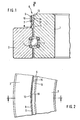
- the seal according to the invention shown in FIG. 1 is arranged between the concentrically arranged races 1 and 2 of a roller bearing rotary connection, between which balls 3 roll on running wires 4.
- the carrier 7 of the seal 6 is spanned by an elastic band 9 made of polymeric material, the ends 10 and 11 of which, as FIG. 2 shows, overlap one another.
- the mutually facing surfaces of the ends 10 and 11 are welded together.
- the seal 6 consists of a at its ends 15 and 16 e.g. by gluing or vulcanizing cohesively connected section of a cross section corresponding to the profile of the seal 6. These measures make it unnecessary to produce special seals 6 for seals of different diameters. Rather, they can be cut to the required length from the profile and connected at their ends in the manner described.
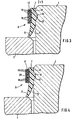
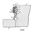
- the seals according to the invention shown in FIGS. 3 to 5 differ from the ones described above in that the band 17 or 22, which is made of a polymeric material, is spirally wound in several layers 18 or 21 around the hollow cylindrical carrier 7.
- an adhesive layer 19 is provided on the side of the band 17 facing the carrier 7, which layer serves, on the one hand, to fix the band 17 overall on the carrier 7 and the individual layers 18 of the band 17 to one another.
- the adhesive layer 19 serves to maintain the tension of the tape 17.
- a spot weld 20 is additionally provided, which covers all the layers 18 of the band 17 and forms a positive connection between them, which additionally ensures the tension of the band 17 is maintained.
- the spot welding 20 can be produced in a simple manner by means of a pin-like heated tool which is pressed onto the band 17 with its end face.
- FIG. 5 shows an embodiment in which all the layers 21 of the band 22 are penetrated by the legs 23 of a U-shaped bracket 24, which also partially penetrate into the carrier 7.
- the position of the band 22 on the carrier 7 and the position of the individual layers 21 of the band 22 are thus positively fixed to one another and the tension of the band 22 is also maintained.
- the band 22 is reinforced by glass fiber strands running in the longitudinal direction of the band 22.
Landscapes
- Engineering & Computer Science (AREA)
- General Engineering & Computer Science (AREA)
- Mechanical Engineering (AREA)
- Gasket Seals (AREA)
- Sealing With Elastic Sealing Lips (AREA)
Claims (8)
Applications Claiming Priority (2)
| Application Number | Priority Date | Filing Date | Title |
|---|---|---|---|
| DE19843426805 DE3426805A1 (de) | 1984-07-20 | 1984-07-20 | Abdichtung |
| DE3426805 | 1984-07-20 |
Publications (2)
| Publication Number | Publication Date |
|---|---|
| EP0172348A1 EP0172348A1 (fr) | 1986-02-26 |
| EP0172348B1 true EP0172348B1 (fr) | 1988-08-24 |
Family
ID=6241162
Family Applications (1)
| Application Number | Title | Priority Date | Filing Date |
|---|---|---|---|
| EP85107382A Expired EP0172348B1 (fr) | 1984-07-20 | 1985-06-14 | Joint d'étanchéité |
Country Status (3)
| Country | Link |
|---|---|
| US (1) | US4573692A (fr) |
| EP (1) | EP0172348B1 (fr) |
| DE (2) | DE3426805A1 (fr) |
Families Citing this family (16)
| Publication number | Priority date | Publication date | Assignee | Title |
|---|---|---|---|---|
| US4643439A (en) * | 1985-10-02 | 1987-02-17 | Ingersoll-Rand Company | Seal for relatively rotatable parts |
| IT1188418B (it) * | 1986-03-04 | 1988-01-14 | Forsheda Ab | Anello di tenuta |
| US4852861A (en) * | 1988-12-29 | 1989-08-01 | The Firestone Tire & Rubber Company | End cap assembly for air spring |
| US4899995A (en) * | 1988-12-29 | 1990-02-13 | Bridgestone/Firestone, Inc. | Clamp ring assembly for air spring |
| US5374037A (en) * | 1993-09-20 | 1994-12-20 | Bridgestone/Firestone, Inc. | Clamp ring assembly for air spring |
| EP0844718A3 (fr) * | 1996-11-21 | 1999-02-03 | RXS Kabelgarnituren Gesellschaft mit beschränkter Haftung | Anneau d'étanchéité en matière synthétique élastique pour accessoires de câble |
| US5941509A (en) | 1997-04-18 | 1999-08-24 | Bridgestone/Firestone, Inc. | Clamp assembly for air actuator |
| US20020011710A1 (en) | 1997-09-25 | 2002-01-31 | Oldenburg Michael R. | Retrofittable severe duty seal for a shaft |
| US6186507B1 (en) | 1997-09-25 | 2001-02-13 | Michael R. Oldenburg | Retrofittable severe duty seal for a shaft |
| US6036180A (en) | 1998-02-26 | 2000-03-14 | Bridgestone/Firestone, Inc. | Tear-drop shaped clamp assembly and tapered end cap for an air spring |
| US6692007B2 (en) | 2001-10-31 | 2004-02-17 | Transcom, Inc. | Seal for a shaft |
| US20060001218A1 (en) * | 2004-06-30 | 2006-01-05 | Rogus Thomas E | Flexible bearing seal |
| US7325794B2 (en) * | 2005-06-06 | 2008-02-05 | Bfs Diversified Products, Llc | Air spring assembly and method |
| US7404547B2 (en) * | 2005-07-27 | 2008-07-29 | Bfs Diversified Products, Llc | Multi-component end member assembly and air spring assembly including the same |
| DE102013208203A1 (de) * | 2013-05-06 | 2014-11-06 | Aktiebolaget Skf | Wälzlager |
| FR3025008B1 (fr) * | 2014-08-25 | 2016-09-16 | Skf Ab | Roulement d'orientation, notamment pour vehicule |
Family Cites Families (10)
| Publication number | Priority date | Publication date | Assignee | Title |
|---|---|---|---|---|
| US1487624A (en) * | 1920-04-26 | 1924-03-18 | Tollefson Tollak | Dust guard |
| US2639954A (en) * | 1948-05-11 | 1953-05-26 | Fafnir Bearing Co | Sealed bearing |
| US2806719A (en) * | 1953-01-12 | 1957-09-17 | Ahlstroem Oy | Sealing means for rotary constructions |
| US2908536A (en) * | 1957-09-03 | 1959-10-13 | Gen Motors Corp | Bearing seal |
| FR1206985A (fr) * | 1958-05-27 | 1960-02-12 | Infilco Inc | Joint pour distributeur rotatif de liquide |
| US3099073A (en) * | 1961-10-02 | 1963-07-30 | Keystone Engineering Company | Method of making anti-friction bearing assembly |
| GB1244171A (en) * | 1968-01-03 | 1971-08-25 | Ilford Ltd | Packages for flat film |
| SE320555B (fr) * | 1968-11-21 | 1970-02-09 | Forsheda Gummifabrik Ab | |
| US3700296A (en) * | 1971-01-15 | 1972-10-24 | Ernst Bugmann | Antifriction bearing |
| FR2296787A1 (fr) * | 1975-01-06 | 1976-07-30 | Hoesch Werke Ag | Palier |
-
1984
- 1984-07-20 DE DE19843426805 patent/DE3426805A1/de not_active Withdrawn
-
1985
- 1985-06-14 DE DE8585107382T patent/DE3564612D1/de not_active Expired
- 1985-06-14 EP EP85107382A patent/EP0172348B1/fr not_active Expired
- 1985-07-15 US US06/755,295 patent/US4573692A/en not_active Expired - Fee Related
Also Published As
| Publication number | Publication date |
|---|---|
| DE3564612D1 (en) | 1988-09-29 |
| US4573692A (en) | 1986-03-04 |
| EP0172348A1 (fr) | 1986-02-26 |
| DE3426805A1 (de) | 1986-01-23 |
Similar Documents
| Publication | Publication Date | Title |
|---|---|---|
| EP0172348B1 (fr) | Joint d'étanchéité | |
| DE3022418C2 (de) | Rahmenförmiger Federkörper | |
| WO2008104434A1 (fr) | Cage axiale en plusieurs parties pour un palier à roulement de grande dimension | |
| DE3331503A1 (de) | Aerodynamisches radiallager | |
| EP1733147B1 (fr) | Stator pour une pompe a vis sans fin excentrique ou un moteur a vis sans fin excentrique selon le principe moineau | |
| DE10317836A1 (de) | Stabilisatorstangenanordnung für ein Kraftfahrzeug | |
| DE1908374B2 (de) | Walzenzapfenabdichtung | |
| DE3445493A1 (de) | Flexibler schlauch mit rechteckigem querschnitt, insbesondere energieleitungstraeger | |
| DE2714963C3 (de) | Elastisches Rohrverbindungsstück | |
| AT391746B (de) | Verbindung fuer einen zahnriemen | |
| EP0684409B1 (fr) | Porte satellites avec anneau collecteur de lubrifiant | |
| DE19708932C1 (de) | Faltenbalg | |
| DE1425453A1 (de) | Druck- und/oder Saugschlauch | |
| EP0146101A2 (fr) | Joint d'étanchéité profilé | |
| DE3612420A1 (de) | Radialwellendichtring | |
| DE2453645C3 (de) | Elastische Verbindungsvorrichtung für zwei im wesentlichen koaxiale Teile | |
| DE2743937C3 (de) | Dichtungsbandwickel aus dauerplastischer Dichtungsmasse mit Stützelementen bei Kabelgarnituren | |
| DE3438379C2 (fr) | ||
| DE2804251A1 (de) | Schlauch, insbesondere staubsaugerschlauch und verfahren zu seiner herstellung | |
| EP3069865B1 (fr) | Conduite multicouches pour véhicules automobiles | |
| DE2604508C3 (de) | Abschlußmanschette für ein Schutzrohr | |
| DE3313907C2 (fr) | ||
| DE3820325C1 (en) | Compensator for compensating for the changes in length of plastic pipes, in particular of glass-fibre-reinforced-plastic pipes | |
| DE3734253A1 (de) | Kurvenfoerdergurt | |
| DE1996044U (de) | Rund- oder walzenbuerste |
Legal Events
| Date | Code | Title | Description |
|---|---|---|---|
| PUAI | Public reference made under article 153(3) epc to a published international application that has entered the european phase |
Free format text: ORIGINAL CODE: 0009012 |
|
| 17P | Request for examination filed |
Effective date: 19850614 |
|
| AK | Designated contracting states |
Designated state(s): DE FR GB |
|
| 17Q | First examination report despatched |
Effective date: 19870916 |
|
| GRAA | (expected) grant |
Free format text: ORIGINAL CODE: 0009210 |
|
| AK | Designated contracting states |
Kind code of ref document: B1 Designated state(s): DE FR GB |
|
| GBT | Gb: translation of ep patent filed (gb section 77(6)(a)/1977) | ||
| REF | Corresponds to: |
Ref document number: 3564612 Country of ref document: DE Date of ref document: 19880929 |
|
| ET | Fr: translation filed | ||
| PLBE | No opposition filed within time limit |
Free format text: ORIGINAL CODE: 0009261 |
|
| STAA | Information on the status of an ep patent application or granted ep patent |
Free format text: STATUS: NO OPPOSITION FILED WITHIN TIME LIMIT |
|
| 26N | No opposition filed | ||
| PGFP | Annual fee paid to national office [announced via postgrant information from national office to epo] |
Ref country code: FR Payment date: 19900522 Year of fee payment: 6 |
|
| PGFP | Annual fee paid to national office [announced via postgrant information from national office to epo] |
Ref country code: GB Payment date: 19900607 Year of fee payment: 6 |
|
| PGFP | Annual fee paid to national office [announced via postgrant information from national office to epo] |
Ref country code: DE Payment date: 19900706 Year of fee payment: 6 |
|
| PG25 | Lapsed in a contracting state [announced via postgrant information from national office to epo] |
Ref country code: GB Effective date: 19910614 |
|
| GBPC | Gb: european patent ceased through non-payment of renewal fee | ||
| PG25 | Lapsed in a contracting state [announced via postgrant information from national office to epo] |
Ref country code: FR Effective date: 19920228 |
|
| PG25 | Lapsed in a contracting state [announced via postgrant information from national office to epo] |
Ref country code: DE Effective date: 19920401 |
|
| REG | Reference to a national code |
Ref country code: FR Ref legal event code: ST |