EP0172462A2 - Dispositif de séparation de liquides de solides - Google Patents
Dispositif de séparation de liquides de solides Download PDFInfo
- Publication number
- EP0172462A2 EP0172462A2 EP85109600A EP85109600A EP0172462A2 EP 0172462 A2 EP0172462 A2 EP 0172462A2 EP 85109600 A EP85109600 A EP 85109600A EP 85109600 A EP85109600 A EP 85109600A EP 0172462 A2 EP0172462 A2 EP 0172462A2
- Authority
- EP
- European Patent Office
- Prior art keywords
- liquid
- solid material
- layer
- filtration layer
- volume filtration
- Prior art date
- Legal status (The legal status is an assumption and is not a legal conclusion. Google has not performed a legal analysis and makes no representation as to the accuracy of the status listed.)
- Withdrawn
Links
Images
Classifications
-
- B—PERFORMING OPERATIONS; TRANSPORTING
- B01—PHYSICAL OR CHEMICAL PROCESSES OR APPARATUS IN GENERAL
- B01D—SEPARATION
- B01D24/00—Filters comprising loose filtering material, i.e. filtering material without any binder between the individual particles or fibres thereof
-
- Y—GENERAL TAGGING OF NEW TECHNOLOGICAL DEVELOPMENTS; GENERAL TAGGING OF CROSS-SECTIONAL TECHNOLOGIES SPANNING OVER SEVERAL SECTIONS OF THE IPC; TECHNICAL SUBJECTS COVERED BY FORMER USPC CROSS-REFERENCE ART COLLECTIONS [XRACs] AND DIGESTS
- Y10—TECHNICAL SUBJECTS COVERED BY FORMER USPC
- Y10T—TECHNICAL SUBJECTS COVERED BY FORMER US CLASSIFICATION
- Y10T436/00—Chemistry: analytical and immunological testing
- Y10T436/25—Chemistry: analytical and immunological testing including sample preparation
- Y10T436/25375—Liberation or purification of sample or separation of material from a sample [e.g., filtering, centrifuging, etc.]
Definitions
- the present invention relates to an instrument of separating liquid from solid material in solid material-containing liquid samples and a process utilizing the instrument.
- This instrument is designed to be advantageously employable in combination with a dry analytical element.
- a blood cell filtration layer be specifically provided to trap the red blood cell therein.
- a representative blood cell filtration layer is described in Japanese Patent Publication 53(1978)-21677 and is composed of a porous material having an appropriate porosity to filter off the blood cell and the like on the surface of the layer. Accordingly, it is suggested that the pore size of the filtration layer is set to be in the range of 1 to 5 ⁇ m which is smaller than the blood cell size (i.e., 7 - 30 um).
- the blood cell and the like do not permeate the filtration layer and are left on the surface of the layer.
- This filtration is named "surface filtration).
- the liquid portion such as serum or plasma is separated from blood cell and the like.
- the analytical procedure using an analytical element provided with the filtration layer such as above is advantageous as compared with the conventional procedure involving centrifugal pretreatment of a whool blood.
- the filtration rate is not high, and further plugging sometimes occurs.
- Japanese Patent Provisional Publication No. 57(1982) -53661 discloses an instrument for recovering serum or plasma by removing solid material from a blood on a layer which is composed of specific glass fibers having a density of 0.1 to 0.5 g/cm 3 and a mean diameter of 0.2 to 0.5 U m. It is not said that this separation instrument shows satisfactory blood cell-separation ability.
- the working example in the publication shows a practical separation of serum (or plasma) from blood cell by setting the amount of serum or plasma to not more than 50% of the whole absorbing capacity of the layer and further by providing a hydrophobic barrier layer.
- An object of the present invention is to provide an instrument for separation of liquid from solid material which is almost free from plugging.
- Another object of the invention is to provide an instrument for separation of liquid from solid material which is employable in place of cetrifugal separation.
- a further object of the invention is to provide an instrument for separation of liquid from solid material which can be manufactured in a small size.
- a still further object of the invention is to provide an instrument for separation of liquid from solid material which can be handled easily without a traind skill.
- a still further object of the invention is to provide an instrument for separation of liquid from solid material which makes it possible to recover the liquid portion in a good yield.
- a still further object of the invention is to provide an instrument for separation of liquid from solid material which makes it possible to shorten the period required for the separation.
- a specific object of the invention is to provide an instrument for separation of a liquid portion out of a whole blood, a fogged urine sample or body fluid, chylous serum in a manner of almost free from plugging.
- the present invention resides in an instrument for separation of liquid from solid material comprising:
- the mechanism of separation taking place in the separation instrument of the present invention is based not on the'surface filtration but on a volume filtration.
- the volume filtration means filtration in which solid materials are trapped within a three-dimensional matrix of the layer, whereby performing efficient separation of liquid from solid material.
- the instrument for separation of liquid from solid material of the invention comprises a pressure-resistant hausing of liquid-impermeable material and a volume filtration layer of fibrous material.
- the volume filtration layer is arranged within the hausing to give a partition between the liquid entrance area space and the liquid exit area space.
- the volume filtration layer is arranged in such a manner that the side face of the volume filtration layer is tightly arranged in contact with an inner face of the hausing.
- the volume filtration layer is fixed onto the inner face of the hausing so as to prevent passage of the solid material along the interface between the side face of the volume filtration layer and the inner face of the hausing.
- the volume filtration layer is composed of fibrous material to give voids arranged at random.
- the solid material is encased within the randomly arranged voids.
- the liquid flows in the direction to the exit. This brings about certain lag of movement between the solid material and the liquid.
- the fibrous material employable for the formation of the volume filtration layer examples include inorganic fibers such as glass fibers and asbestos; natural organic fibers such as cotton fiber, pulp and silk; semisynthetic and synthetic fibers such as viscose rayon, cuprammonium rayon, cellulose acetate, partially formalized polyvinyl alcohol, polyethylene, polypropylene, polyvinyl chloride, polystyrene, polyester(e.g., polyethylene terephthalate); woven fabric composed of these fibers; and knitted material composed of these fibers.
- inorganic fibers such as glass fibers and asbestos
- natural organic fibers such as cotton fiber, pulp and silk
- semisynthetic and synthetic fibers such as viscose rayon, cuprammonium rayon, cellulose acetate, partially formalized polyvinyl alcohol, polyethylene, polypropylene, polyvinyl chloride, polystyrene, polyester(e.g., polyethylene terephthalate); woven fabric composed of these fibers; and knitted
- the employable woven fabric include a variety of fabric.
- plain weave fabrics made of warp and weft are preferred.
- plain weave fabrics thin cloth, muslin, broadcloth and poplin are preferred.
- similar fabrics of other materials such as natural fibers such as kapok, flax, hemp, ramie and silk, chemical fibers such as fibers of viscose rayon, cuprammonium rayer, cellulose acetate, vinylon and poly- etheylene terephthalate and mixtures of cotton fiber and chemical fibers are also employable.
- the glass fiber is particularly preferred.
- the fibrous materials can be subjected to any of a variety of treatments such as a treatment for rendering hydrophilic, a treatment for removing absorbing capacity, and a treatment for imparting absorbing capacity before or after the formation of layer.
- the volume filtration layer generally has a void ratio of not less than approx. 90%, preferably not less than 95% and up to 98%.
- the fibrous material preferably has a thickness in the range of approx. 0.1 to 5 ⁇ m and a length in the range of approx. 100 to 4,000 ⁇ m.
- the fibers of the preferred ranges can be obtained by classification using a sieve of approx. 100 - 200 mesh (Tyler's mesh).
- the void ratio is generally selected depending on the particle size of the solid material to be removed.
- the blood cell is preferably filtered off using a volume filtration layer of glass fibers in a density of approx. 0.02 to 0.15 g/cm 3 , particularly in a density of approx. 0.04 to 0.08 g/cm 3 .
- the hausing employed for the formation of a separation instrument of the invention is made of a liquid-impermeable material and possesses a room for encasing the aforementioned volume filtration layer therein.
- the hausing there is no specific limitation on the shape of the hausing, as far as the hausing can encase the volume filtration layer therein keeping it for preventing passing of the liquid sample along the interface between the inner face of the hausing and the side face of the volume filtration layer.
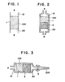
- a most advantageous and simple shape may be a narrow cylinder illustrated in Fig. 1.
- the structure having an exit of narrower diameter than the diameter of the main body encasing the volume filtration layer is preferred to efficiently recover the separated liquid.
- the separation instrument can be employed in conjunction with an independently designed adaptor for performing measurement of the volume of the liquid sample as well as the analysis.
- the entrance allows introduction of the liquid sample into the volume filtration layer. Accordingly, a simple opening can serve as the entrance.
- the separation instrument of the invention can be so shaped as to match with a liquid supplying instrument (e.g., blood collecting syringe) for employment in conjunction, as illustrated in Fig. 2.
- a liquid supplying instrument e.g., blood collecting syringe
- the liquid impermeable material employed for the preparation of the hausing may be a polymer material having a glass transition temperature of not lower than room temperature, one of other plastics, glass, and ceramic.
- a solid material-containing liquid sample such as a whole blood sample is supplied through the entrance directly or using a pipette, dispensor, syringe, etc.
- the supplied whole blood sample is subjected to the volume filtration within the volume filtration layer so that blood cells are trapped inside of the layer and plasma moves toward the exit.
- the movement of the liquid is preferably accelerated by the application of moderate pressure difference using an appropriate pressing or pressure-reducing means.
- One of these means may be installed separately from the separation instrument or attached to the separation instrument.
- the application of the pressure difference for causing rapid movement of the liquid toward the liquid exit can be adopted only in the filtration system functioning on the volume filtration of liquid from solid material.
- the pressure difference is introduced into the conventional separation system based on the surface filtration of liqud from solid material, the blood cell trapped on the upper surface of the filtration layer is broken and undergoes hemolysis. Accordingly, the difference of filtration system gives significant difference on the yield of liquid recovery.
- the separation of liquid from solid material in 1 ml. of a whole blood sample is performed under pressure difference using the separation instrument of the invention, plasma amounting to several tens % based on the theoretical amount is recovered within a short period of time such as within a few minutes.
- the recoverable plasma amounts at most to 10 % (e.g., 20 - 30 ⁇ l per 1 ml. of a whole blood sample) and the filtration requires a long period of time.
- the filtration layer is partially plugged to cause hemolysis.
- resulting plasma is.not appropriate for use in an analysis.
- the degree of the pressure difference applied on the volume filtration layer is determined depending on the viscosity of the liquid sample, nature, density, and void ratio of the material of the filtration layer, and so forth, but should be not higher than approx. 1 pressure atmosphere. Under the pressure difference up to the such level, the movement of liquid is accelerated without occurrence of hemolysis.
- the separation instrument of the present invention preferably has a solid material-trapping layer on the surface of the volume filtration layer on the exit side.
- the solid material-trapping layer traps solid materials having leaked out of the volume filtration layer. Such leakage of the solid material may accidentally happen or may be caused by wrongly set pressure difference, liquid application rate, etc.
- the solid material-trapping layer functions based on the surface filtration for preventing leakage of the solid material into the exit.
- the solid material-trapping layer is fixed onto the inner face of the hausing by its side face in the same manner as in the volume filtration layer.
- the solid material-trapping layer not only prevents leakage of the solid material but also accelerates the movement of the liquid through absorbing power caused due to a specific arrangement that the solid material-trapping layer is made more dense than the volume filtration layer.
- the solid material-trapping layer is a porous layer composed of a fibrous or non-fibrous porous material.
- the solid material-trapping layer is advantageously prepared to have more dense structure than the volume filtration layer has.
- the solid material-trapping layer preferably has a mean pore size of smaller than the void size of the volume filtration layer.
- the void ratio preferably is in the range of approx. 65 to 95%, more preferably in the range of approx. 70 to 93%, and the density of the layer preferably is in the range of 0. 1 to 0.5 g/cm 3 .
- the solid material-trapping layer can be prepared from a fibrous material as mentioned for the preparation of the volume filtration layer.
- the adjustement of the void ratio of the solid material-trapping layer can be made by pressing or the like.
- the solid material-trapping layer can be made of a not-fibrous material.
- the non-fibrous material include blushed polymers which are produced by processing polymers such as polycarbonates, polyamides and cellulose esters in a known manner.
- blushed polymers there are mentioned Microfilter (tradename, available from Fuji Photo Film Co., Ltd.), Milipore (tradename, available from Milipore Corp.) and Methylicel (tradename, available from German Instrument Corp.), all of which are commerically available.
- porous materials are described in detail in Japanese Patent Provisional Publications No. 49(1974)-53888 and No. 55(1980)-164356 and United States Patent 3,992,158. Moreover, the details of the preparation of the layer are given in the copending United States Patent Application Serial No. 728,404 and European Patent Application No. 85105215.9).
- the separation instrument of the present invention can have a net structure on the exit-side surface of the volume filtration layer, on the interface between the volume filtration layer and the solid material-trapping layer, or on the exit-side surface of the solid material-trapping layer so that the volume filtration layer can be mechanically reinforced.
- Preferred examples of the net structure include nets of polyesters, polyamides and polyurethanes, sieves thereof, nets for collecting planktons, veils, and glass filters.
- Fig. 1 is a section schematically illustrating an elemental structure of the separation instrument of the present invention.
- the numeral 100 indicates a hausing (or hollow support member).
- the numeral 1 indicates a volume filtration layer which extends along the lateral section of the hollow space of the hausing 100 to divide it into two room, that is, a room 10 on the side of the liquid entrance A and a room 20 on the side of the liquid exit B.
- the volume filtration layer 1 for instance, is prepared in the form of a disk from a glass fiber sheet of a density of 0.06 g/cm to have a volume of approx. 0.3 ml.
- the volume filtration layer is tightly fixed to the inner surface of the hausing 100 so as to prevent leakage of the solid material contained in an applied liquid sample.
- the solid material-containing liquid sample such as a whole blood sample is supplied onto the volume filtration layer 1 through the entrance A directly or indirectly. Subsequently, the upper surface of the volume filtration layer is pressed at a pressure difference of 0.025 atm. pressure.
- the blood cell is three- dimensionaly trapped inside of the layer and only the liquid portion such as serum and plasma rapidly moves toward the exit B.
- 1 ml. of a whole blood sample gives approx. 0.5 ml of a liquid portion.
- a sample amounting to 10 ⁇ 1 is enough for performing a clinical test on single item. Therefore, if the yield of the liquid portion is approx. 25% (recovery of 0.12 ml of liquid portion, i.e., plasma, from 1 ml. of blood sample), the clinical test can be performed on ten items.
- Fig. 2 is a section schematically illustrating an embodiment of the separation instrument according to the invention.
- a solid material-trapping layer 2 is provided to the surface of the volume filtration layer 1 on the exit B side (or in the room 20).
- the solid material-trapping layer 2 is prepared, for example, in the form of a disk from glass filter sheets having a density of approx. 0.21 g/cm 3 to have a volume of approx. 0.3 ml.
- the composite layer that is, a combination of the volume filtration layer and the solid material-trapping layer, has totally a volume of approx. 0.6 ml.
- the composite structure can be formed by simply combining the volume filtration layer 1 and the solid material-trapping layer 2. Otherwise, the composite structure can be formed by a paper-making process to give a single unit structure.
- formed separation instrument can be employed in the same manner as in the embodiment illustrated in Fig. 1. Since the separation instrument shown in Fig. 2 is equipped with the solid material-trapping layer 2, this instrument can be employed under larger pressure difference and moreover gives increase of the liquid recovery.
- Fig. 3 is a section schematically illustrating a combination of an embodiment of the instrument according to the invention and a liquid-receiving means (adaptor) 200.
- the liquid separated from the solid material in the layers is directly received by the adaptor. Therefore, no loss is expected on the separated liquid, and moreover the recovery of the liquid can be controlled to match with the capacity of the adaptor.
- the instrument of the invention for separating a liquid from a solid material can be employed singly or in combination with other liquid-supplying means or liquid-receiving means.
- the instrument enables to efficiently separate a liquid out of a solid material-containing liquid. Further, only a shorter period of time is required to accomplish the desired separation. Furthermore, no skill is required in the separation procedure. The operation involved in the separation procedure is very simple.
- the instrument of the invention can be formed in a simple structure, and accrodingly is available at a low cost. Further, it is very easy to prepare a compact instrument according to the invention.
- the use of the instrument of the invention makes it unnecessary to transfer the liquid sample which is generally done in the conventional separation process involving centrifugal separation. Therefore, the liquid sample can be handled without receiving biologial contamination. It may be advantageous to employ the separation instrument of the invention in combination with a known sheet-type analytical element to conduct biochemical analysis such as a clinical test.
- a glass fiber filter GA-100 (Toyo Filter Paper Co., Ltd., Japan) was cut to prepare square pieces (approx. 2 mm x 2 mm) and dispersed in 800 ml of water by means of a homogenizer (Ace Homogenizer AM-11, manufactured by Nippon Seiki Co., Ltd., Japan). The dispersion was filtered over a sieve of Tyler mesh No. 12 to remove lumps of fibers. The resulting glass fiber dispersion contained 15 mg. of glass fiber per 10 ml (determined by filtering the dispersion on a membrane filter having a pore size of 0.22 ⁇ m (Microfilter, tradename, produced by Fuji Photo Film Co., Ltd. and weighing the glass fibers collected on the filter after drying).
- a small amount of glass wool (generally employed in gas chromatographic column) to form a filter.
- the filter was placed 80 ml of the glass fiber dispersion prepared in the (1) above to form a glass fiber layer.
- the formed layer was freeze-dried in the wet conditions and then dried under reduced pressure.
- the resulting glass fiber layer (volume filtration layer) had a volume of approx. 1.5 ml.
- a blood was collected, and heparin sodium was immediately added to the blood in an amount of 1/200 of the blood.
- One ml. of the so treated blood was slowly introduced into the separation instrument prepared in the (2) above.
- a piston was introduced into the syringe and pushed slowly in such a manner that the piston advances by a length corresponding to 0.05 ml per 10 sec.
- a liquid discharged from the end of the syringe was continuously collected. When leakage of blood cell was noted, the collection was ended. Approx. 100 ul. of plasma was collected: yield approx. 20%.
- Example 2 In the same syringe of an inner diameter of 6 mm as in Example was introduced 30 sheets of disks (diameter 6 mm) of a glass fiber filter GA-100 (approx. 90 mg.) to make a voluminous layer. The resulting voluminous layer was compressed by means of a piston to give a layer having a volume of approx. 0.4 ml.
- Example 1-(1) On the solid material-trapping layer prepared in the (1) above was placed a glass fiber dispersion (solid material 8 mg/10 ml of dispersion) prepared in the same manner as in Example 1-(1) to form a glass fiber layer. The resulting layer was freeze-dried in the wet state and dried.
Landscapes
- Chemical & Material Sciences (AREA)
- Chemical Kinetics & Catalysis (AREA)
- Investigating Or Analysing Biological Materials (AREA)
- External Artificial Organs (AREA)
- Medicines Containing Material From Animals Or Micro-Organisms (AREA)
- Filtration Of Liquid (AREA)
Applications Claiming Priority (2)
| Application Number | Priority Date | Filing Date | Title |
|---|---|---|---|
| JP158784/84 | 1984-07-31 | ||
| JP15878484A JPS6138608A (ja) | 1984-07-31 | 1984-07-31 | 全血からの血漿の分離器具および分離方法 |
Publications (2)
| Publication Number | Publication Date |
|---|---|
| EP0172462A2 true EP0172462A2 (fr) | 1986-02-26 |
| EP0172462A3 EP0172462A3 (fr) | 1987-08-19 |
Family
ID=15679259
Family Applications (1)
| Application Number | Title | Priority Date | Filing Date |
|---|---|---|---|
| EP85109600A Withdrawn EP0172462A3 (fr) | 1984-07-31 | 1985-07-31 | Dispositif de séparation de liquides de solides |
Country Status (3)
| Country | Link |
|---|---|
| US (1) | US4810394A (fr) |
| EP (1) | EP0172462A3 (fr) |
| JP (1) | JPS6138608A (fr) |
Cited By (2)
| Publication number | Priority date | Publication date | Assignee | Title |
|---|---|---|---|---|
| DE10318708A1 (de) * | 2003-04-25 | 2004-11-25 | Awg Innovative Wasser- Und Abwassertechnik Gmbh | Filter für die Flüssigkeitsfiltration und Verfahren für die Flüssigkeitsfiltration und für die Reinigung solcher Filter, insbesondere für Wasseraufbereitungsanlagen |
| WO2012171560A1 (fr) * | 2011-06-15 | 2012-12-20 | Pfaff Tim | Séparateur de plasma ou de sérum |
Families Citing this family (31)
| Publication number | Priority date | Publication date | Assignee | Title |
|---|---|---|---|---|
| JPS639449A (ja) * | 1986-07-01 | 1988-01-16 | テルモ株式会社 | 血液成分分離用器具 |
| DE3635598A1 (de) * | 1986-10-20 | 1988-05-05 | Eppendorf Geraetebau Netheler | Pipettiervorrichtung mit einem aufsteckkonus fuer eine pipettenspitze sowie pipettenspitze fuer eine solche pipettiervorrichtung |
| US5423989A (en) * | 1988-05-19 | 1995-06-13 | Chemtrack, Inc. | Plasma forming device |
| DE3904872A1 (de) * | 1989-02-17 | 1990-08-23 | Gert Schlueter | Verfahren und vorrichtung zum sammeln und abtrennen von zellen, partikeln od. dgl. aus koerperfluessigkeit fuer die mikroskopische diagnostik |
| US5156811A (en) * | 1990-11-07 | 1992-10-20 | Continental Laboratory Products, Inc. | Pipette device |
| AU643089B2 (en) * | 1991-02-15 | 1993-11-04 | Toa Medical Electronics Co., Ltd. | Apparatus for regulating liquid temperature |
| US5186843A (en) * | 1991-07-22 | 1993-02-16 | Ahlstrom Filtration, Inc. | Blood separation media and method for separating plasma from whole blood |
| JPH05188053A (ja) * | 1992-01-10 | 1993-07-27 | Sanwa Kagaku Kenkyusho Co Ltd | 血液から血清又は血漿成分を分離する器具 |
| US5460974A (en) * | 1992-10-13 | 1995-10-24 | Miles Inc. | Method of assaying whole blood for HDL cholesterol |
| US5766552A (en) * | 1993-04-20 | 1998-06-16 | Actimed Laboratories, Inc. | Apparatus for red blood cell separation |
| US5660798A (en) * | 1993-04-20 | 1997-08-26 | Actimed Laboratories, Inc. | Apparatus for red blood cell separation |
| US5652148A (en) * | 1993-04-20 | 1997-07-29 | Actimed Laboratories, Inc. | Method and apparatus for red blood cell separation |
| AU695988B2 (en) * | 1994-05-19 | 1998-08-27 | Vaughan Clift | Method and apparatus for the collection, storage, and real time analysis of blood and other bodily fluids |
| US6241886B1 (en) | 1995-06-09 | 2001-06-05 | Toyo Boseki Kabushiki Kaisha | Plasma separation filter |
| JP3664328B2 (ja) | 1996-01-19 | 2005-06-22 | 富士写真フイルム株式会社 | 血漿または血清試料の調製方法 |
| JP3664286B2 (ja) * | 1996-12-24 | 2005-06-22 | 富士写真フイルム株式会社 | 血液濾過ユニット |
| JP3685283B2 (ja) * | 1997-02-13 | 2005-08-17 | 富士写真フイルム株式会社 | 血漿採取具 |
| JP3903098B2 (ja) * | 1997-07-18 | 2007-04-11 | 富士フイルム株式会社 | 血液濾過方法 |
| JP3932639B2 (ja) * | 1998-01-19 | 2007-06-20 | 東洋紡績株式会社 | 血漿あるいは血清分離フィルター |
| US6241947B1 (en) * | 1998-01-27 | 2001-06-05 | Fuji Photo Film Co., Ltd. | Chemical analysis system and blood filtering unit |
| JPH11237378A (ja) * | 1998-02-19 | 1999-08-31 | Fuji Photo Film Co Ltd | 全血から血清を分離する方法 |
| US6471868B1 (en) * | 1998-04-10 | 2002-10-29 | Fuji Photo Film Co., Ltd. | Method of preparing glass fiber filter |
| US6068775A (en) * | 1998-04-13 | 2000-05-30 | Circe Biomedical, Inc. | Removal of agent from cell suspension |
| US6036659A (en) * | 1998-10-09 | 2000-03-14 | Flexsite Diagnostics, Inc. | Collection device for biological samples and methods of use |
| JP3990505B2 (ja) * | 1999-02-02 | 2007-10-17 | 富士フイルム株式会社 | 血液成分の分析方法 |
| US6659288B2 (en) | 2000-05-16 | 2003-12-09 | Fuji Photo Film Co., Ltd. | Plasma- or serum-collecting device |
| US6869405B2 (en) * | 2001-03-30 | 2005-03-22 | Becton, Dickinson And Company | Blunt cannula and filter assembly and method of use with point-of-care testing cartridge |
| US7407742B2 (en) | 2002-02-27 | 2008-08-05 | Sanko Junyaku Co., Ltd. | Plasma or serum separator, plasma or serum sampling method, plasma or serum separating method, test carrier and glass fiber |
| US7228973B2 (en) * | 2003-05-23 | 2007-06-12 | Ahlstrom Mt. Holly Springs, Llc | Nonwoven fibrous media especially useful for the separation of blood constituents |
| USD679826S1 (en) * | 2005-07-11 | 2013-04-09 | Eppendorf Ag | Filter pipette tip |
| JP6954865B2 (ja) * | 2018-05-15 | 2021-10-27 | 富士フイルム株式会社 | ファイバーロッド、血液採取器具、及び血液検査キット |
Family Cites Families (10)
| Publication number | Priority date | Publication date | Assignee | Title |
|---|---|---|---|---|
| US3050373A (en) * | 1959-12-09 | 1962-08-21 | Miles Lab | Diagnostic composition for detecting glucose |
| US3448041A (en) * | 1965-06-14 | 1969-06-03 | Roy L Swank | Method and apparatus for treating blood preliminary to its use in transfusions |
| US4032688A (en) * | 1973-08-31 | 1977-06-28 | Pall Corporation | Seamless tubular nonwoven webs and filters thereof |
| IL51209A (en) * | 1976-03-25 | 1981-02-27 | Baxter Travenol Lab | Blood filter |
| US4073723A (en) * | 1976-11-15 | 1978-02-14 | Swank Roy L | Anti-coagulating and filtering blood |
| US4116845A (en) * | 1977-06-17 | 1978-09-26 | Pioneer Filters, Inc. | High capacity blood transfusion micro filter |
| GB2018151B (en) * | 1978-03-06 | 1982-12-08 | Asahi Chemical Ind | Seperation of leukocytes from leukocyte-containing suspension by filtration |
| US4246107A (en) * | 1978-03-06 | 1981-01-20 | Asahi Kasei Kogyo Kabushiki Kaisha | Separation of lymphocytes from lymphocyte-containing suspension by filtration |
| JPS603367B2 (ja) * | 1979-10-09 | 1985-01-28 | 旭化成株式会社 | 白血球分離法および白血球分離材 |
| JPS56176012U (fr) * | 1980-12-23 | 1981-12-25 |
-
1984
- 1984-07-31 JP JP15878484A patent/JPS6138608A/ja active Granted
-
1985
- 1985-07-31 EP EP85109600A patent/EP0172462A3/fr not_active Withdrawn
-
1987
- 1987-09-02 US US07/094,034 patent/US4810394A/en not_active Expired - Lifetime
Cited By (4)
| Publication number | Priority date | Publication date | Assignee | Title |
|---|---|---|---|---|
| DE10318708A1 (de) * | 2003-04-25 | 2004-11-25 | Awg Innovative Wasser- Und Abwassertechnik Gmbh | Filter für die Flüssigkeitsfiltration und Verfahren für die Flüssigkeitsfiltration und für die Reinigung solcher Filter, insbesondere für Wasseraufbereitungsanlagen |
| DE10318708B4 (de) * | 2003-04-25 | 2005-09-15 | Awg Innovative Wasser- Und Abwassertechnik Gmbh | Filter für die Flüssigkeitsfiltration und Verfahren für die Flüssigkeitsfiltration und für die Reinigung solcher Filter, insbesondere für Wasseraufbereitungsanlagen |
| WO2012171560A1 (fr) * | 2011-06-15 | 2012-12-20 | Pfaff Tim | Séparateur de plasma ou de sérum |
| US9222931B2 (en) | 2011-06-15 | 2015-12-29 | Tim Pfaff | Plasma or serum separator |
Also Published As
| Publication number | Publication date |
|---|---|
| JPS6138608A (ja) | 1986-02-24 |
| JPH0552463B2 (fr) | 1993-08-05 |
| EP0172462A3 (fr) | 1987-08-19 |
| US4810394A (en) | 1989-03-07 |
Similar Documents
| Publication | Publication Date | Title |
|---|---|---|
| US4810394A (en) | Process and apparatus for removing solid material including blood cells from whole blood | |
| EP0160916B1 (fr) | Membre d'un élément de test pour l'analyse d'un solide dans un échantillon liquide | |
| CA1307448C (fr) | Appareil pour la separation du sang a basse pression | |
| US5368729A (en) | Solid phase extraction device | |
| US20010044615A1 (en) | Plasma collecting device | |
| KR100446030B1 (ko) | 혈액여과장치 | |
| DE69623180T2 (de) | Filter zum Trennen von Plasma, Verfahren zur Plasmatrennung unter Verwendung dieses Filters und Trennungsvorrichtung für Plasma | |
| JP3903098B2 (ja) | 血液濾過方法 | |
| CA1102710A (fr) | Traduction non-disponible | |
| US20110168645A1 (en) | Method for preparing a fluid fraction from blood | |
| US6225130B1 (en) | Method of separating serum from whole blood | |
| US6375856B1 (en) | Method of recovering blood filtration residues | |
| US6328167B1 (en) | Blood filter cartridge | |
| US20010035375A1 (en) | Filter for arrayable micro-centrifuge | |
| JPH0223831B2 (fr) | ||
| JP3870468B2 (ja) | 血漿又は血清分離フィルター | |
| CN220040471U (zh) | 一种微流控芯片 | |
| JP3644169B2 (ja) | 血漿あるいは血清分離フィルターおよび血漿あるいは血清分離方法 | |
| JP4006551B2 (ja) | 血漿あるいは血清分離フィルター | |
| JP3551080B2 (ja) | 分離装置 | |
| US20020185429A1 (en) | Filter for arrayable micro-centrifuge | |
| JPH058383B2 (fr) | ||
| JPH058384B2 (fr) | ||
| JPH1138001A (ja) | 血液濾過ユニット | |
| KR920007851B1 (ko) | 크로마토그래피 분리관 |
Legal Events
| Date | Code | Title | Description |
|---|---|---|---|
| PUAI | Public reference made under article 153(3) epc to a published international application that has entered the european phase |
Free format text: ORIGINAL CODE: 0009012 |
|
| AK | Designated contracting states |
Designated state(s): DE GB |
|
| PUAL | Search report despatched |
Free format text: ORIGINAL CODE: 0009013 |
|
| AK | Designated contracting states |
Kind code of ref document: A3 Designated state(s): DE GB |
|
| 17P | Request for examination filed |
Effective date: 19871016 |
|
| 17Q | First examination report despatched |
Effective date: 19880317 |
|
| STAA | Information on the status of an ep patent application or granted ep patent |
Free format text: STATUS: THE APPLICATION HAS BEEN WITHDRAWN |
|
| 18W | Application withdrawn |
Withdrawal date: 19890621 |
|
| R18W | Application withdrawn (corrected) |
Effective date: 19890621 |
|
| RIN1 | Information on inventor provided before grant (corrected) |
Inventor name: MASUDA, NOBUHITOFUJI PHOTO FILM CO. LTD. |