EP0172753A2 - Vorrichtung zum Falten von Wäschestücken - Google Patents
Vorrichtung zum Falten von Wäschestücken Download PDFInfo
- Publication number
- EP0172753A2 EP0172753A2 EP85305949A EP85305949A EP0172753A2 EP 0172753 A2 EP0172753 A2 EP 0172753A2 EP 85305949 A EP85305949 A EP 85305949A EP 85305949 A EP85305949 A EP 85305949A EP 0172753 A2 EP0172753 A2 EP 0172753A2
- Authority
- EP
- European Patent Office
- Prior art keywords
- conveyor
- article
- feed
- transfer conveyor
- roller
- Prior art date
- Legal status (The legal status is an assumption and is not a legal conclusion. Google has not performed a legal analysis and makes no representation as to the accuracy of the status listed.)
- Granted
Links
Images


Classifications
-
- B—PERFORMING OPERATIONS; TRANSPORTING
- B65—CONVEYING; PACKING; STORING; HANDLING THIN OR FILAMENTARY MATERIAL
- B65H—HANDLING THIN OR FILAMENTARY MATERIAL, e.g. SHEETS, WEBS, CABLES
- B65H45/00—Folding thin material
- B65H45/02—Folding limp material without application of pressure to define or form crease lines
- B65H45/04—Folding sheets
-
- D—TEXTILES; PAPER
- D06—TREATMENT OF TEXTILES OR THE LIKE; LAUNDERING; FLEXIBLE MATERIALS NOT OTHERWISE PROVIDED FOR
- D06F—LAUNDERING, DRYING, IRONING, PRESSING OR FOLDING TEXTILE ARTICLES
- D06F89/00—Apparatus for folding textile articles with or without stapling
Definitions
- the invention relates to a laundry folding unit, particularly for flat-work articles such as sheets, table-cloths etc.
- Adjacent lanes should be capable of operating together to process wider articles which may occupy two or more lanes.
- An article may need to be laterally folded once or twice, or not at all.
- a laundry folding unit for receiving articles to be folded from an ironing machine, which unit can be combined with another for single or double folds; by- passed when no fold is required; and which is capable of running independently or in conjunction with parallel units to give the facility of flexible multi-lane operation.
- Other mechanisms sometimes employed include plate devices which insert a fold line of an article into the nip of contra-rotating rollers.
- Another arrangement includes hinged plates or blades to which free-running wheels or rollers are mounted. The article is guided over the mechanism and at the appropriate time the plate or blade is raised and the free-running wheels or rollers engage with an overhead contra-rotating roller which grips a portion of the article causing it to reverse and pass folded under the plate mechanism.
- the mechanical movements become noisy and unstable.
- the weight of the mechanisms makes it difficult to synchronise a number for combined operation of several lanes of a multi-lane machine.
- the present invention seeks to provide an improved folding system.
- a laundry folding unit in the feed path of articles in a laundry machine, the unit comprising a feed conveyor on which articles to be folded are received; a roller which runs against the feed conveyor to present a folding nip therewith; a transfer conveyor located above the roller; drive means for driving the transfer conveyor at least as fast as the feed conveyor and in the same direction; a bridging mechanism operable to feed articles from the feed conveyor to the transfer conveyor, the transfer conveyor being arranged to transfer articles from the feed conveyor and on to the feed path of the machine beyond the roller to bypass the foller if desired; a brake for stopping the transfer conveyor; and a timing mechanism responsive to the passage of an article through the machine, the arrangement-being such that (a) a fold in an article may be effected by operating the bridging mechanism to feed the leading part of the article on to the transfer conveyor, withdrawing the bridging mechanism and braking the transfer conveyor to allow the feed conveyor to continue to feed the trailing part of the article towards the roller so that a fold line of the article is
- Double folds or multiple folds may be effected by arranging a second or further fold units similar to the first further along the feed path for the articles.
- the feed.conveyor has a downwardly inclined portion and the said roller runs against this downwardly inclined portion. It is to be understood that the downwardly inclined portion, although preferable, is not essential.
- the preferred unit of the present invention is compact and allows units to be arranged one immediately above the next. Thus, two or more lateral folds may be made, and it is important to note that the mechanism is particularly suitable for making one-third folds.
- the unit readily gives the type of fold which folds the article with the side in contact with the feed conveyor (in practice the ironed side), and which delivers it with the edges underneath after two folds have been made. From the point of view of neatness and customer acceptability this type of fold is best.
- the drive arrangement required can be so simplified that adjacent units can be assembled side by side across a multi-lane machine to operate independently or together.
- the drive mechanism may comprise a shaft running across the machine to which one of each of the transfer conveyor rollers is clutched when drive is required.
- a preferred alternative is to drive the transfer conveyor via frictional co-operation with a drive conveyor running over said roller. When the brake is operated the transfer conveyor slips on the drive conveyor.
- the bridging mechanism is preferably a set of fingers displaceable to project between bands of the feed conveyor.
- the braking mechanism is preferably an electromagnetic brake acting on a roller over which the transfer conveyor passes.
- the unit comprises a feed conveyor 1 along which are fed articles to be folded.
- Conveyor 1 consists of a set of parallel bands with spaces between, and runs over a guide 2 and a folding roller 3.
- the folding roller is the end roller of a drive conveyor 4 which passes over a tubular support 5 and around another end roller 6.
- a transfer conveyor 7 which runs around two end rollers 8 and 9 and a large brake roller 10.
- Drive conveyor 4 is positively driven by a drive shaft and transfer conveyor 7 is driven by contact with the drive conveyor.
- a fold gap 11 exists between the feed conveyor 1 and the transit conveyor 7, and a bridging mechanism is provided to controllably bridge the gap when required.
- the bridging mechanism comprises a set of fingers 12 which in the position shown project between the bands of conveyor 1. The fingers are mounted to pivot about the axis of guide 2 and are moved between the bridging position shown and a related position where they lie beneath the conveyor belt 1 by means of a pneumatic ram 13.
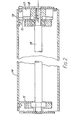
- roller 10 in cross-section.
- the roller is a hollow tube 14 mounted on end brackets 15 which rotate on a spindle 16.
- an armature 17 which is fixed to the frame of the machine by an anchor plate 18.
- a brake plate 19 is coupled to one of the rotary brackets 15. Operation of the brake attracts the brake plate to the armature and stops the roller.
- a timing mechanism (not shown in Figure 3) detects the article 20 to be folded and measures its length and position. As shown in Figure 3a the bridging fingers 12 are operated to bridge the gap to the transfer conveyor and the leading edge of the article is thus fed on to the transfer conveyor. After a time determined by the timing mechanism the brake of roller 10 is operated. This stops the conveyor which then slips with respect to the drive conveyor.
- the bridging mechanism is operated to withdraw the fingers and open the fold gap just prior to the braking of the transfer conveyor and the trailing part of the article is fed down by the feed conveyor to form a loop which tucks into the folding nip between the feed conveyor and the folding roller 3.
- the brake can be released and the transfer conveyor restarted. This can be after a very short delay - perhaps as little as 100 mSec.
- the article will be drawn back against the drag of the restarted transfer conveyor and in many circumstances this actually reduces frictional resistance and helps draw out creases.
- the article is thus drawn between the feed conveyor and the folding roller and a fold is effected. It will be seen that the article may be laterally folded at any required point depending on the setting of the timing mechanism. Usually articles will be folded in half, but the system is suitable for forming a one-third fold, for example.
- FIG. 4 there is shown the arrangement of two units of the kind shown in Figure 1 in a machine for effecting two folds successively if necessary.
- the folding units are illustrated generally at A and B.
- the feed conveyor serves both. Units A and B and finally delivers the laundry articles to a delivery table 23.
- An important feature of the invention is the bypass facility, which can be seen from Figure 4. Normally, the bridging fingers are in the lowered position. Thus, if the bridging fingers are not operated, either deliberately because no fold is required or accidentally because the article has missed being detected by the measuring sensors, then the article passes on through the folding nip and is not folded. In these circumstances continuous running of the machine is not impeded. This is a fail-safe feature. Alternatively, an article can be deliberately by-passed around a t'old station by raising the bridging fingers and feeding it to the transfer conveyor.
- the transfer conveyor is not stopped and instead of the article being drawn back between the feed conveyor and the folding roller the article is carried over the braking roller 10 and fed from Unit A to unit B or from unit B back to the feed conveyor 1 and thence to the delivery table.
- a useful feature of this by-pass mode is that it can be employed for a long article, the trailing part of which may still be engaged in a previous and slower machine, for example an ironer. The leading part of the article may slip relative to the transfer conveyor. If, on the other hand, such an article were by-passed through the folding nip, the positive pull on the article may cause tearing. Thus, it will be seen that by appropriate control an article may be folded once, twice, or not at all. With this arrangement by- pass is effected merely by control of the bridging fingers and non-activation of the brake. No physical movement of substantial components is necessary.
- Figure 4 shows the positions of the sensing switches of the turning mechanism.
- the switches can be mechanical micro-switches or optical switches, for example.
- Two sensor switches Sl and S2 are located prior to the first fold station A. The switches detect the leading and trailing edges of an article. They are connected to a measuring circuit which in known manner determines the length of the article, and also the position of the required fold line, whether it be half, quarter or third the way along the article, for example.
- the bridging finger mechanism As the article approaches the transfer conveyor and is detected by switch S2 the bridging finger mechanism is operated. When the fold line of the article as determined by the measuring circuit reaches the appropriate position the bridging fingers are retracted and the conveyor brake is applied. At this point the article forms a loop and the fold line is conveyed into the folding nip. The brake is released and the fold cycle completed. Brake release can be effected a short fixed time after brake operation, to allow for the fold line to be engaged in the folding nip.
- the measuring circuit When the measuring circuit is adjusted to establish the half-length of an article, the article will be folded in half. To fold in thirds, the control is adjusted to establish the leading third length and make the first fold. This is followed by a half-length measurement to make the second fold. The article is then folded to one third of its size. For the second fold station, only one additional switch, S3, is required, since the length of the article has already been established by the first two sensors and the measuring circuit.
- Simultaneous parallel operation of folding units in adjacent lanes of a multi-lane machine can be achieved as follows.
- Switching sensors are located on the conveyor between the lanes. When an article is wide enough to contact these sensors the respective lanes are automatically combined for simultaneous operation. Alternatively the selection to combine lanes can be made manually by the machine operator from a control panel.
- FIG 5 there is shown the machine of Figure 4 in schematic plan view, to illustrate the multi-lane operation.
- the feed conveyor 1 and delivery table are four lanes wide. For convenience the individual conveyor bands are not shown.
- the lanes are marked P,Q,R,S.
- Each lane has an independent pair of folding units A and B, marked PA, PB etc., with associated independent measuring and timing equipment.
- the lanes can be run as two pairs, one pair and two singles, one triple and one single or one quadruple width lane. No complicated coupling or uncoupling is necessary for this, since the necessary drive in the embodiment described is taken by friction from the feed conveyor and the timing controls can be effective to operate the bridging fingers and conveyor brakes independently or in unison.
Landscapes
- Engineering & Computer Science (AREA)
- Textile Engineering (AREA)
- Folding Of Thin Sheet-Like Materials, Special Discharging Devices, And Others (AREA)
- Control And Other Processes For Unpacking Of Materials (AREA)
- Treatment Of Fiber Materials (AREA)
- Centrifugal Separators (AREA)
- Holders For Apparel And Elements Relating To Apparel (AREA)
Priority Applications (1)
| Application Number | Priority Date | Filing Date | Title |
|---|---|---|---|
| AT85305949T ATE62890T1 (de) | 1984-08-22 | 1985-08-21 | Vorrichtung zum falten von waeschestuecken. |
Applications Claiming Priority (2)
| Application Number | Priority Date | Filing Date | Title |
|---|---|---|---|
| GB848421346A GB8421346D0 (en) | 1984-08-22 | 1984-08-22 | Laundry folding mechanism |
| GB8421346 | 1984-08-22 |
Publications (3)
| Publication Number | Publication Date |
|---|---|
| EP0172753A2 true EP0172753A2 (de) | 1986-02-26 |
| EP0172753A3 EP0172753A3 (en) | 1987-09-16 |
| EP0172753B1 EP0172753B1 (de) | 1991-04-24 |
Family
ID=10565689
Family Applications (1)
| Application Number | Title | Priority Date | Filing Date |
|---|---|---|---|
| EP85305949A Expired - Lifetime EP0172753B1 (de) | 1984-08-22 | 1985-08-21 | Vorrichtung zum Falten von Wäschestücken |
Country Status (5)
| Country | Link |
|---|---|
| US (1) | US4738440A (de) |
| EP (1) | EP0172753B1 (de) |
| AT (1) | ATE62890T1 (de) |
| DE (2) | DE3582631D1 (de) |
| GB (1) | GB8421346D0 (de) |
Cited By (3)
| Publication number | Priority date | Publication date | Assignee | Title |
|---|---|---|---|---|
| DE4300712A1 (de) * | 1993-01-13 | 1994-07-14 | Kuhn Waeschereimaschinen Gmbh | Faltmaschine für rechteckige Textilien |
| EP3686339A1 (de) * | 2019-01-24 | 2020-07-29 | Herbert Kannegiesser GmbH | Verfahren und vorrichtung zum mangeln und falten von wäschestücken |
| WO2020182254A1 (de) * | 2019-03-08 | 2020-09-17 | Schmale-Holding Gmbh & Co. | Vorrichtung und verfahren zum automatischen falten und stapeln von tüchern |
Families Citing this family (11)
| Publication number | Priority date | Publication date | Assignee | Title |
|---|---|---|---|---|
| US5556360A (en) * | 1991-03-27 | 1996-09-17 | Chicago Dryer Company | High production folder construction |
| JP4073556B2 (ja) * | 1998-09-21 | 2008-04-09 | 株式会社小森コーポレーション | 折機の平行折装置 |
| US7137554B2 (en) * | 2000-02-23 | 2006-11-21 | Dynetics Engineering Corporation, Inc. | Card mailer system and method of preparing card packages for mailing |
| US20070021283A1 (en) * | 2005-07-19 | 2007-01-25 | Richard Leifer | System and method for the automated folding of textiles |
| US7617656B2 (en) * | 2007-03-16 | 2009-11-17 | The Procter & Gamble Company | Method and apparatus for selective folding or redirecting |
| JP5096261B2 (ja) * | 2008-08-19 | 2012-12-12 | 株式会社プレックス | 布片処理装置 |
| WO2011051868A1 (en) * | 2009-10-29 | 2011-05-05 | Fameccanica.Data S.P.A. | Pants-type diaper and corresponding manufacturing process |
| US9248056B2 (en) | 2011-01-13 | 2016-02-02 | Fameccanica.Data S.P.A. | Pant-type diaper and corresponding manufacturing process and apparatus |
| US8672824B2 (en) | 2011-03-17 | 2014-03-18 | Fameccanica.Data S.P.A. | Process and equipment for folding a pant type diaper |
| US10065831B2 (en) | 2013-05-16 | 2018-09-04 | The Procter & Gamble Company | Methods and apparatuses for folding absorbent articles |
| NL2023841B1 (en) * | 2019-09-18 | 2021-05-18 | Vega Systems B V | An apparatus for sorting and stacking textile products |
Family Cites Families (18)
| Publication number | Priority date | Publication date | Assignee | Title |
|---|---|---|---|---|
| US2011934A (en) * | 1930-05-31 | 1935-08-20 | American Laundry Mach Co | Folding machine |
| US2158896A (en) * | 1938-03-15 | 1939-05-16 | Roland W Charles | Automatic folding machine |
| GB516222A (en) * | 1938-05-23 | 1939-12-28 | Leo Marcus Kahn | Improvements in and relating to machines for folding towels, sheets and the like |
| DE1066535B (de) * | 1952-06-27 | |||
| US3154726A (en) * | 1961-10-12 | 1964-10-27 | Super Laundry Mach Co | Folding machine controller |
| DE1929411A1 (de) * | 1969-06-10 | 1970-12-17 | Grantham Frederick W | Waeschefaltmaschine |
| US3642270A (en) * | 1969-09-26 | 1972-02-15 | Super Laundry Machinery Co | Small piece laundry folding machine |
| US3684274A (en) * | 1970-06-10 | 1972-08-15 | Frederick W Grentham | Laundry folder with wicket clamp |
| US3744785A (en) * | 1971-06-07 | 1973-07-10 | C Grantham | Shop towel folder |
| US3980290A (en) * | 1972-01-06 | 1976-09-14 | Team Industries | Towel folder |
| DE2610778A1 (de) * | 1976-03-15 | 1977-09-29 | Frankenthal Ag Albert | Schwertfalzwerk |
| DE2815599C2 (de) * | 1978-04-11 | 1985-01-03 | Kleindienst GmbH, 8900 Augsburg | Vorrichtung zum Falten von Wäschestücken |
| DE2944638C2 (de) * | 1979-11-05 | 1984-11-22 | E. & E. Peters, U. Wenck & Co Vertriebsgesellschaft Mbh, 2000 Hamburg | Faltvorrichtung für Wäschestücke od.dgl. |
| DK146301C (da) * | 1981-03-25 | 1984-03-26 | Jensen Ejnar & Soen As | Foldemaskine til foldning af boejelige ark, f.eks. toejstykker, langs en foldelinie, der forloeber vinkelret paa den retning, hvori arket fremfoeres |
| FR2520665B1 (fr) * | 1982-02-04 | 1987-12-24 | Martin Sa | Machine de pliage de plaques |
| US4650173A (en) * | 1984-07-13 | 1987-03-17 | Paper Converting Machine Co. | Method of operating a diaper producing machine and apparatus |
| US4678173A (en) * | 1985-12-11 | 1987-07-07 | Fieldcrest Cannon, Inc. | Apparatus for automatically and continuously feeding and folding textile articles |
| US4682977A (en) * | 1986-07-21 | 1987-07-28 | Paper Converting Machine Company | Apparatus for folding spaced segments of web material |
-
1984
- 1984-08-22 GB GB848421346A patent/GB8421346D0/en active Pending
-
1985
- 1985-08-21 AT AT85305949T patent/ATE62890T1/de active
- 1985-08-21 DE DE8585305949T patent/DE3582631D1/de not_active Expired - Lifetime
- 1985-08-21 EP EP85305949A patent/EP0172753B1/de not_active Expired - Lifetime
- 1985-08-21 DE DE198585305949T patent/DE172753T1/de active Pending
-
1987
- 1987-06-03 US US07/057,779 patent/US4738440A/en not_active Expired - Fee Related
Cited By (4)
| Publication number | Priority date | Publication date | Assignee | Title |
|---|---|---|---|---|
| DE4300712A1 (de) * | 1993-01-13 | 1994-07-14 | Kuhn Waeschereimaschinen Gmbh | Faltmaschine für rechteckige Textilien |
| EP3686339A1 (de) * | 2019-01-24 | 2020-07-29 | Herbert Kannegiesser GmbH | Verfahren und vorrichtung zum mangeln und falten von wäschestücken |
| US11208757B2 (en) | 2019-01-24 | 2021-12-28 | Herbert Kannegiesser Gmbh | Method and apparatus for ironing and folding laundry items |
| WO2020182254A1 (de) * | 2019-03-08 | 2020-09-17 | Schmale-Holding Gmbh & Co. | Vorrichtung und verfahren zum automatischen falten und stapeln von tüchern |
Also Published As
| Publication number | Publication date |
|---|---|
| ATE62890T1 (de) | 1991-05-15 |
| GB8421346D0 (en) | 1984-09-26 |
| EP0172753B1 (de) | 1991-04-24 |
| EP0172753A3 (en) | 1987-09-16 |
| DE172753T1 (de) | 1987-04-30 |
| US4738440A (en) | 1988-04-19 |
| DE3582631D1 (de) | 1991-05-29 |
Similar Documents
| Publication | Publication Date | Title |
|---|---|---|
| EP0172753B1 (de) | Vorrichtung zum Falten von Wäschestücken | |
| US4701155A (en) | Buckle chute folder with clamp | |
| US4885853A (en) | Spreader feeder apparatus | |
| US4234179A (en) | Laundry folding machine | |
| US4059258A (en) | Double fold automatic folding apparatus | |
| US4954203A (en) | Labelling system | |
| US3361424A (en) | Cross folder with sheet elevating means | |
| US4093205A (en) | French folder construction | |
| US4502676A (en) | Document handling machine with double collector and method of operation | |
| US5628718A (en) | Method of operating a folder | |
| US3260518A (en) | Small piece folder | |
| US3462138A (en) | Laundry folder | |
| GB2221226A (en) | Feeding pieces of laundry to a mangle | |
| US4109902A (en) | Apparatus for the continuous zigzag folding of a material web | |
| GB1582082A (en) | Sheet folding machine and method | |
| WO1993010032A1 (en) | Apparatus for the high speed stacking of paper sheets both by accordion-like folding of a continuous band and by superimposing separate sheets | |
| US3829081A (en) | Small piece folder | |
| US5617804A (en) | Conveying device for feeding textile articles from multiple feed stations | |
| US4300896A (en) | Device for folding materials to be folded | |
| US7703756B2 (en) | Machine for converting a fabric from a rolled fabric into a superimposingly folded fabric for delivery to a dyeing machine | |
| GB1111690A (en) | Mechanism for automatically producing prefolded diapers | |
| US2750186A (en) | Folding apparatus | |
| US3476379A (en) | Laundry folding devices | |
| JPH0753123B2 (ja) | 生地付きスライドフアスナーチエーンの切断加工装置 | |
| US4729555A (en) | Compact high speed stacker |
Legal Events
| Date | Code | Title | Description |
|---|---|---|---|
| PUAI | Public reference made under article 153(3) epc to a published international application that has entered the european phase |
Free format text: ORIGINAL CODE: 0009012 |
|
| AK | Designated contracting states |
Designated state(s): AT BE CH DE FR GB IT LI LU NL SE |
|
| RAP1 | Party data changed (applicant data changed or rights of an application transferred) |
Owner name: WEIR, HENRY JOHN |
|
| ITCL | It: translation for ep claims filed |
Representative=s name: BARZANO' E ZANARDO MILANO S.P.A. |
|
| EL | Fr: translation of claims filed | ||
| TCNL | Nl: translation of patent claims filed | ||
| DET | De: translation of patent claims | ||
| PUAL | Search report despatched |
Free format text: ORIGINAL CODE: 0009013 |
|
| AK | Designated contracting states |
Kind code of ref document: A3 Designated state(s): AT BE CH DE FR GB IT LI LU NL SE |
|
| 17P | Request for examination filed |
Effective date: 19880310 |
|
| 17Q | First examination report despatched |
Effective date: 19881201 |
|
| GRAA | (expected) grant |
Free format text: ORIGINAL CODE: 0009210 |
|
| AK | Designated contracting states |
Kind code of ref document: B1 Designated state(s): AT BE CH DE FR GB IT LI LU NL SE |
|
| PG25 | Lapsed in a contracting state [announced via postgrant information from national office to epo] |
Ref country code: BE Effective date: 19910424 Ref country code: AT Effective date: 19910424 |
|
| REF | Corresponds to: |
Ref document number: 62890 Country of ref document: AT Date of ref document: 19910515 Kind code of ref document: T |
|
| REF | Corresponds to: |
Ref document number: 3582631 Country of ref document: DE Date of ref document: 19910529 |
|
| ITF | It: translation for a ep patent filed | ||
| ET | Fr: translation filed | ||
| PGFP | Annual fee paid to national office [announced via postgrant information from national office to epo] |
Ref country code: CH Payment date: 19910724 Year of fee payment: 7 |
|
| PGFP | Annual fee paid to national office [announced via postgrant information from national office to epo] |
Ref country code: SE Payment date: 19910816 Year of fee payment: 7 |
|
| PG25 | Lapsed in a contracting state [announced via postgrant information from national office to epo] |
Ref country code: LU Free format text: LAPSE BECAUSE OF NON-PAYMENT OF DUE FEES Effective date: 19910831 |
|
| PLBE | No opposition filed within time limit |
Free format text: ORIGINAL CODE: 0009261 |
|
| STAA | Information on the status of an ep patent application or granted ep patent |
Free format text: STATUS: NO OPPOSITION FILED WITHIN TIME LIMIT |
|
| 26N | No opposition filed | ||
| PG25 | Lapsed in a contracting state [announced via postgrant information from national office to epo] |
Ref country code: SE Effective date: 19920822 |
|
| PG25 | Lapsed in a contracting state [announced via postgrant information from national office to epo] |
Ref country code: LI Effective date: 19920831 Ref country code: CH Effective date: 19920831 |
|
| REG | Reference to a national code |
Ref country code: CH Ref legal event code: PL |
|
| EUG | Se: european patent has lapsed |
Ref document number: 85305949.1 Effective date: 19930307 |
|
| PGFP | Annual fee paid to national office [announced via postgrant information from national office to epo] |
Ref country code: FR Payment date: 19970827 Year of fee payment: 13 |
|
| PGFP | Annual fee paid to national office [announced via postgrant information from national office to epo] |
Ref country code: NL Payment date: 19970831 Year of fee payment: 13 |
|
| PGFP | Annual fee paid to national office [announced via postgrant information from national office to epo] |
Ref country code: DE Payment date: 19970927 Year of fee payment: 13 |
|
| PG25 | Lapsed in a contracting state [announced via postgrant information from national office to epo] |
Ref country code: NL Free format text: LAPSE BECAUSE OF NON-PAYMENT OF DUE FEES Effective date: 19990301 |
|
| PG25 | Lapsed in a contracting state [announced via postgrant information from national office to epo] |
Ref country code: FR Free format text: LAPSE BECAUSE OF NON-PAYMENT OF DUE FEES Effective date: 19990430 |
|
| NLV4 | Nl: lapsed or anulled due to non-payment of the annual fee |
Effective date: 19990301 |
|
| PG25 | Lapsed in a contracting state [announced via postgrant information from national office to epo] |
Ref country code: DE Free format text: LAPSE BECAUSE OF NON-PAYMENT OF DUE FEES Effective date: 19990601 |
|
| REG | Reference to a national code |
Ref country code: FR Ref legal event code: ST |
|
| PGFP | Annual fee paid to national office [announced via postgrant information from national office to epo] |
Ref country code: GB Payment date: 19990810 Year of fee payment: 15 |
|
| PG25 | Lapsed in a contracting state [announced via postgrant information from national office to epo] |
Ref country code: GB Free format text: LAPSE BECAUSE OF NON-PAYMENT OF DUE FEES Effective date: 20000821 |
|
| GBPC | Gb: european patent ceased through non-payment of renewal fee |
Effective date: 20000821 |