EP0173029A2 - Verfahren zur Programmsteuerung der Kristallisation in einem Vakuumbehälter - Google Patents
Verfahren zur Programmsteuerung der Kristallisation in einem Vakuumbehälter Download PDFInfo
- Publication number
- EP0173029A2 EP0173029A2 EP85108125A EP85108125A EP0173029A2 EP 0173029 A2 EP0173029 A2 EP 0173029A2 EP 85108125 A EP85108125 A EP 85108125A EP 85108125 A EP85108125 A EP 85108125A EP 0173029 A2 EP0173029 A2 EP 0173029A2
- Authority
- EP
- European Patent Office
- Prior art keywords
- consistency
- set value
- value
- curve
- time
- Prior art date
- Legal status (The legal status is an assumption and is not a legal conclusion. Google has not performed a legal analysis and makes no representation as to the accuracy of the status listed.)
- Granted
Links
Images


Classifications
-
- C—CHEMISTRY; METALLURGY
- C13—SUGAR INDUSTRY
- C13B—PRODUCTION OF SUCROSE; APPARATUS SPECIALLY ADAPTED THEREFOR
- C13B30/00—Crystallisation; Crystallising apparatus; Separating crystals from mother liquors ; Evaporating or boiling sugar juice
- C13B30/02—Crystallisation; Crystallising apparatus
- C13B30/022—Continuous processes, apparatus therefor
- C13B30/025—Continuous processes, apparatus therefor combined with measuring instruments for effecting control of the process
-
- C—CHEMISTRY; METALLURGY
- C13—SUGAR INDUSTRY
- C13B—PRODUCTION OF SUCROSE; APPARATUS SPECIALLY ADAPTED THEREFOR
- C13B25/00—Evaporators or boiling pans specially adapted for sugar juices; Evaporating or boiling sugar juices
- C13B25/06—Evaporators or boiling pans specially adapted for sugar juices; Evaporating or boiling sugar juices combined with measuring instruments for effecting control of the process
Definitions
- This invention relates to a method of programing the consistency of massecuite to be controlled intermittently in an automatic boiling apparatus in a pan.
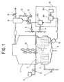
- a vacuum boiling apparatus is shown by way of example in FIGURE 1. It comprises a parallel side pan 1 having a calandria type heating area 2.
- the solution F e.g., syrup
- Heating steam S is supplied to the heating area 2 through a control valve 4 to heat and concentrate the solution by vaporization.
- the solution continues to be supplied until a concentration enabling crystallization is reached.
- a seed is added from a feeder 5 through a valve 6 to form appropriate nuclear grains. While the interior of the pan is watched, water or the solution is supplied to avoid the bonding of the nuclear grains and the formation of undesirable nuclear grains (false grains), so that the concentration of the solution and the growing of crystals may be continued.
- the solution is further concentrated to facilitate the growth of crystals.
- the solution is added to increase its volume in the pan to a certain level, and when a predetermined crystal size has been obtained, the massecuite 7 is discharged through a discharge valve 8.
- the massecuite is separated by a centrifugal separator into the crystals and the solution.
- the solution is recycled for boiling.
- a signal e indicating the consistency of massecuite is transmitted from a consistency meter 15, such as a rheometer, to the control portion 161 of a sequence control system 16.
- the system 16 also includes a program setter 162 for feeding a set value e s of consistency to the control portion 161, and a valve actuator 163 for opening or closing the solution control valve 3 or the water control valve 9 in accordance with the output of the control portion 161.
- a level gage for determining the level of the massecuite 7 in the pan, a pressure control device for maintaining an appropriate vacuum degree in the pan, etc. are also provided, though not shown in FIGURE 1.
- FIGURE 7 A conventional method for the program control of the boiling operation is shown in FIGURE 7.
- Part (A) shows the changes in the measured value e m and set value e s of consistency in a specific area of the crystal growing process in which the solution is boiled, and part (B) shows the operation of the solution control valve 3.
- the ideal curve C can, however, be maintained only when various parameters, including the amount of steam in the pan, its vacuum degree and the purity of the solution, are maintained at appropriate levels. It is difficult to maintain any such ideal pattern of control if, for example, the amount of the steam S in the pan or its vacuum degree has greatly changed.
- This speed of crystal growth under ideal conditions is expressed by an upper limit curve for consistency if a sensor (consistency meter) is used for detecting the ratio of crystallization and the factors dictating the growth of crystals from the solution (its concentration, supersaturation, etc.).
- This object is attained by a method which comprises establishing curves defining the upper and lower limits of an allowable range of consistency and starting from each point at which the measured value of consistency coincides with a set value, increasing the set value along the curve defining the upper limit, holding the set value when it has been increased to a specific degree, or when a specific length of time has passed, and increasing the set value along the curve defining the lower limit after a line representing the set value has crossed the curve defining the lower limit.
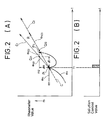
- FIGURE 2 A method embodying this invention is shown in FIGURE 2.
- the measured value e m of consistency is shown by way of example as having reached the level m 1 of a set value e s at time t l .
- the measured value e m has a peak P 1 .
- the inventors of this invention know from their experience of actual operation that no single curve is sufficient to define the consistency of massecuite, but that there exists a specific peak range in which the/value of consistency changes from one point to another.
- This range is shown as a region R defined by and between two curves both starting from the point P 1 , i.e., a curve C 1 defining the upper limit of the range (upper limit curve) and a curve C 2 defining its lower limit (lower limit curve).
- ⁇ m and ⁇ t which determine points Q 21 and Q 22' are so selected based on experience that the point at which the value of e m is expected to reach another peak P 2 may fall on the line e s22 between points Q 21 and Q 22 .
- the program is established to define a pair of limit curves starting from each peak of the value e m substantially as hereinabove described. It enables the achievement of the results of program control comparable to those obtained in accordance with any conventional control curve, since all of the peaks P 1 , P 2 , ... of the value e m fall within the respective ranges R unless there is any disorder in the parameters dictating the boiling operation in the pan.
- the shift of the peak value of consistency from P 1 to P 2 is equivalent to the shift from m 1 to m 2 in FIGURE 7.
- the peak P 2 may appear earlier than at point Q 21 and not fall on the horizontal line e s22 .
- the consistency is, however, so programed as to increase in proportion to time along the curve e s21 which coincides with curve C 1 , and which represents smaller values than m 2 . Therefore, the value e m and hence the peak P 2 thereof are kept from rising above the upper limit defined by curve C 1 .
- the peak of the value e m is so corrected as to fall on the horizontal line e s22 and maintained at least on the upper or lower limit curve as hereinabove set forth, it is possible to maintain the value e m of consistency within the allowable range R throughout each cycle of boiling operation and thereby improve greatly any serious variation in boiling time and the production of defective products which have hitherto been unavoidable.
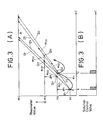
- FIGURE 3 An embodiment of this invention which can simplify the algorithm is shown in FIGURE 3. This method can effectively be employed to establish a program without affecting the advantages of this invention.
- the area in which boiling is carried out is appropriately divided into a plurality of regions.
- the initial value of massecuite consistency in a particular region is shown at m l , and its final value at m n . If the consistency of massecuite reaches m 1 at time t 1 , there are established two straight lines D 1 and D 2 starting from the peak P 1 defined by t 1 and m l , and defining an allowable range R therebetween.
- the set value after time t 1 is given by a one-dot chain line e s21 coinciding with the upper limit line D 1 until it increases by ⁇ m to m 2 .
- the value increasing along line e s21 reaches m 2 at point Q 21 and is thereafter maintained at m 2 as shown by a horizontal line es22.
- Line e s22 meets the lower limit line D 2 at point Q22 and the value is thereafter given by a straight line e s23 coinciding with line D 2 .
- the next program is set when the peak P 2 of the value e m has fallen on any of lines e s21 to e s23 at time t 2 .
- the set value after t 2 is given by a two-dot chain line e s31 coinciding with the upper limit line D' 1 until it increases by ⁇ m from m 2 to m 3 .
- the value reaches m 3 at point Q31 and is maintained at m 3 as shown by a horizontal line es32.
- the line e s32 meets the lower limit line D' 2 at point Q32 and the set value is thereafter given by a line e s33 coinciding with the lower limit line D' 2 .
- the foregoing procedure is repeated whenever the value e m has reached the set value, so that each peak of the value e m may be maintained within the range R until the consistency of massecuite reaches the level m n .
- the same procedure is repeated for establishing two lines for the program control of consistency in the next region.
- FIGURE 4 Another embodiment of this invention is shown in FIGURE 4, and characterized by a still simpler algorithm.
- the arer in which boiling is carried out is appropriately divided into a plurality of regions, and the initial value of massecuite consistency in a particular region is shown at m l , and its final value at m n , as is the case with the method shown in FIGURE 3.
- an upper limit curve or line D 1 is established as starting from the peak P 1 defined by t 1 and m 1 .
- the set value after time t 1 is given by a one-dot chain line e s21 coinciding with the upper limit curve or line D 1 until it increases by ⁇ m to m 2 .
- the value reaches m 2 at point Q 21 and is thereafter maintained at m 2 as shown by a horizontal line e s22 .
- the length of time from P 1 to Q 21 is shown as ⁇ t.
- the constant value represented by the horizontal line e s22 is maintained for a specific length of time t 0 . Therefore, the time at which point Q 22 appears with the lapse of time t 0 after point Q 21 is expressed as t 1 +-t+t 0 .
- a second feature of the method shown in FIGURE 4 resides in the procedure for establishing the lower limit curves D 2 , D 2 ', ...
- the first lower limit curve D 1 is defined by a straight line extending from point P 1 to Q 22 and has a gradient expressed as ⁇ m/(-t + t 0 ).
- the line e s23 is so established as to extend from the line as hereinabove defined.
- the program for the next cycle of operation is so set as to start at the peak P 2 which appears at time t 2 when the measured value e m of consistency falls on any of lines e s21 to e s23 .
- the program for each further cycle is set in accordance with the upper and lower limit lines which are based on either a specific increment ⁇ m in consistency over the peak, or a specific length of time ⁇ t which has passed after the peak.
- the method shown in FIGURE 4 is based on a specific increment ⁇ m in consistency.
- the consistency increases by ⁇ m from m 2 to m 3 at point Q 31 on the upper limit curve or line D 1 starting from peak P 2 .
- the straight line e s31 extending from P 2 to Q 31 defines the second upper limit line D 1 '.
- the length of time required for the consistency to increase from P 2 to Q 31 is expressed as ⁇ t'.
- the set value after point Q 31 is maintained constant for the same length of time t 0 along a horizontal line e s32 as along the horizontal line es22.
- the line e s32 meets at point Q 32 the lower limit line D 2 ' which is defined by a straight line extending from P 2 to Q 32 .
- a line e s33 extends from point Q 32 .
- point Q 31 appears on the upper limit curve or line D 1 with the lapse of time -t after peak P 2 .
- the increase m' in consistency from m 2 to m 3 is greater than -m, and the upper limit line set for each cycle of operation is closer to D 1 . Therefore, it is possible to decrease the number of the regions into which the whole process for boiling from the beginning to completion of crystallization is divided.
- the horizontal and lower limit lines are established in the same way as when they are based on ⁇ m.
- FIGURE 5 A still simpler procedure for establishing the lower limit lines is shown in FIGURE 5, while the procedure shown in FIGURE 4 is repeated for establishing the upper limit line D 1 .
- the method of FIGURE 5 is characterized by a lower limit line which is defined by a straight line D 2 extending below line D 1 and representing a specific difference m 0 therefrom. While the lines e s21' e s22 and e s23 starting from point P1 and the lines e s31' es32 and es33 starting from point P 2 are established in accordance with exactly the same procedure as those shown in FIGURE 4, only the upper limit line is established as starting from each peak, and the lower limit line D 2 is not varied.
- point Q 31 is that point on the upper limit curve or line D 1 at which the consistency m 3 which is m higher than m 2 at point P 2 is obtained. It is, however, possible to select that point on D 1 which is reached with the lapse of time t after P 2 . In this case, if the consistency increases by m' from m 2 to m 3 , m' is greater than m, and the upper limit line D 1' is closer to D 1 . Therefore, it is possible to decrease the number of the regions into which the whole boiling process from the beginning to completion of crystallization is divided.
- the horizontal and lower limit lines are established in the same way as is shown in FIGURE 5.
- the lower limit line D 2 is finalized as initially defined and does not vary. Therefore, it can be established by a still simpler algorithm.
- FIGURES 3 to 5 have been described as showing a method for programing consistency only in a particular portion of the boiling area
- FIGURE 6 shows the program control of consistency over the whole boiling area which is divided into a plurality of regions T 1 , T 2 , ... and T n .
- the upper limit curves or lines y 1 to y n for the regions T 1 to T nr respectively are defined by a combination of curves or lines which gradually increase in gradient.
- the method of this invention provides the following advantages; (1) It is possible to decrease drastically the possibility of abnormal change in boiling time and defective production that might otherwise result from a great deviation, from the limit curves, of the curve joining the peak values of massecuite consistency in the event any variation has developed in any of the parameters, such as the amount of steam or pressure in the pan, or the purity of the solution.
- the curves defining the set value of consistency are automatically corrected so as to fall within the allowable range to prevent any defective production unless the disorder in the parameters is fatal. Therefore, the method of this invention is easy to carry out even by an unskilled operator and drastically mitigates the mental burden which the job of watching the operation of a pan has hitherto imposed on even a highly skilled person.
- the method of this invention can be carried out by employing a simplified procedure as shown in FIGURES 3 to 5.
- the stability of operation is ensured only if a program is set by two lines for each particular region. As no complicated programing is required, the method of this invention can be carried out by an inexpensive apparatus.
Landscapes
- Chemical & Material Sciences (AREA)
- Life Sciences & Earth Sciences (AREA)
- Biochemistry (AREA)
- Organic Chemistry (AREA)
- Crystallography & Structural Chemistry (AREA)
- Feedback Control In General (AREA)
- Saccharide Compounds (AREA)
- Control Of Steam Boilers And Waste-Gas Boilers (AREA)
Applications Claiming Priority (2)
| Application Number | Priority Date | Filing Date | Title |
|---|---|---|---|
| JP137439/84 | 1984-07-03 | ||
| JP59137439A JPS6115700A (ja) | 1984-07-03 | 1984-07-03 | 結晶缶プログラム制御方法 |
Publications (3)
| Publication Number | Publication Date |
|---|---|
| EP0173029A2 true EP0173029A2 (de) | 1986-03-05 |
| EP0173029A3 EP0173029A3 (en) | 1989-02-15 |
| EP0173029B1 EP0173029B1 (de) | 1991-10-09 |
Family
ID=15198647
Family Applications (1)
| Application Number | Title | Priority Date | Filing Date |
|---|---|---|---|
| EP85108125A Expired - Lifetime EP0173029B1 (de) | 1984-07-03 | 1985-07-01 | Verfahren zur Programmsteuerung der Kristallisation in einem Vakuumbehälter |
Country Status (6)
| Country | Link |
|---|---|
| US (1) | US4848321A (de) |
| EP (1) | EP0173029B1 (de) |
| JP (1) | JPS6115700A (de) |
| AU (1) | AU577602B2 (de) |
| DE (1) | DE3584337D1 (de) |
| DK (1) | DK299185A (de) |
Cited By (1)
| Publication number | Priority date | Publication date | Assignee | Title |
|---|---|---|---|---|
| EP0244079A3 (en) * | 1986-03-25 | 1989-02-22 | Nabisco Brands, Inc. | Process and apparatus for controlling the composition of a mixture leaving an evaporator |
Families Citing this family (4)
| Publication number | Priority date | Publication date | Assignee | Title |
|---|---|---|---|---|
| JPH01293878A (ja) * | 1988-05-23 | 1989-11-27 | Nikkiso Co Ltd | 筒型ケーシング用弾性キャップおよびその筒型ケーシング用弾性キャップを使用した筒型ケーシングの液漏れ防止方法 |
| FR2669510B1 (fr) * | 1990-11-22 | 1993-01-22 | Fcb | Procede discontinu de cristalisation d'un sirop et appareil pour la mise en óoeuvre de ce procede. |
| US20040258589A1 (en) * | 2003-06-23 | 2004-12-23 | Golovanoff Gregory W. | Method and apparatus for crystal growth |
| US9309576B2 (en) * | 2013-03-13 | 2016-04-12 | Rockwell Automation Technologies, Inc. | Sugar crystallization control system and method |
Family Cites Families (11)
| Publication number | Priority date | Publication date | Assignee | Title |
|---|---|---|---|---|
| DE1004110B (de) * | 1954-09-11 | 1957-03-07 | Ditmar Zonen N V | Kontrollvorrichtung an Siedepfannen, insbesondere zum Verkochen von Zuckersaeften auf Kristall |
| CH447980A (fr) * | 1964-06-05 | 1967-11-30 | Soc D Raffineries De Sucre De | Appareil pour la régulation de la cristallisation du saccharose |
| FR1455912A (fr) * | 1965-06-01 | 1966-10-21 | Bull General Electric | Perfectionnements aux systèmes d'exploitation d'un signal d'information binaire |
| CH483272A (fr) * | 1967-05-02 | 1969-12-31 | Belge Atel Reunies | Appareil de cuisson pour la cristallisation en continu |
| FR2101257A5 (de) * | 1970-03-19 | 1972-03-31 | Fives Lille Cail | |
| DE2311231C3 (de) * | 1973-03-07 | 1984-01-12 | Siemens AG, 1000 Berlin und 8000 München | Verfahren zur Regelung des Kristallisationsprozesses von Zuckerlösungen in einem diskontinuierlich arbeitenden Kochapparat |
| US4056364A (en) * | 1974-08-30 | 1977-11-01 | Amstar Corporation | Two stage continuous crystallization apparatus with controls |
| US4155774A (en) * | 1977-08-09 | 1979-05-22 | Randolph Ellwood A | Process for controlling the rate of growth of particulate masses |
| JPS5912279A (ja) * | 1982-07-09 | 1984-01-21 | 株式会社東芝 | 冷蔵庫 |
| FR2562908B1 (fr) * | 1984-04-11 | 1986-06-27 | Fives Cail Babcock | Procede de conduite automatisee d'un appareil de cristallisation a marche continue pour la production de sucre |
| DE3563981D1 (de) * | 1984-04-19 | 1988-09-01 | Tongaat Hulett Group Ltd | Massecuite supersaturation monitor |
-
1984
- 1984-07-03 JP JP59137439A patent/JPS6115700A/ja active Granted
-
1985
- 1985-06-28 AU AU44424/85A patent/AU577602B2/en not_active Ceased
- 1985-07-01 DE DE8585108125T patent/DE3584337D1/de not_active Expired - Lifetime
- 1985-07-01 DK DK299185A patent/DK299185A/da not_active Application Discontinuation
- 1985-07-01 EP EP85108125A patent/EP0173029B1/de not_active Expired - Lifetime
-
1988
- 1988-11-17 US US07/272,438 patent/US4848321A/en not_active Expired - Fee Related
Cited By (1)
| Publication number | Priority date | Publication date | Assignee | Title |
|---|---|---|---|---|
| EP0244079A3 (en) * | 1986-03-25 | 1989-02-22 | Nabisco Brands, Inc. | Process and apparatus for controlling the composition of a mixture leaving an evaporator |
Also Published As
| Publication number | Publication date |
|---|---|
| EP0173029B1 (de) | 1991-10-09 |
| US4848321A (en) | 1989-07-18 |
| DK299185D0 (da) | 1985-07-01 |
| JPS6115700A (ja) | 1986-01-23 |
| JPS6365317B2 (de) | 1988-12-15 |
| EP0173029A3 (en) | 1989-02-15 |
| DE3584337D1 (de) | 1991-11-14 |
| AU577602B2 (en) | 1988-09-29 |
| AU4442485A (en) | 1986-01-09 |
| DK299185A (da) | 1987-01-02 |
Similar Documents
| Publication | Publication Date | Title |
|---|---|---|
| US10822666B2 (en) | Method for obtaining crystals from a mother solution, and crystallization device suitable for this purpose | |
| EP2778238A2 (de) | Zuckerkristallisationssteuerungssystem und Verfahren | |
| EP0173029A2 (de) | Verfahren zur Programmsteuerung der Kristallisation in einem Vakuumbehälter | |
| US4009045A (en) | Continuous crystallization process and apparatus | |
| US20040258589A1 (en) | Method and apparatus for crystal growth | |
| JP5024578B2 (ja) | 非スクロース物質の結晶化方法 | |
| JPS6337080B2 (de) | ||
| SU1124035A1 (ru) | Способ регулировани процесса кристаллизации сахаросодержащих растворов | |
| Broadfoot et al. | Planning for improved control of batch high-grade strikes | |
| JPS62104600A (ja) | 結晶缶プログラム制御方法 | |
| JPS6365318B2 (de) | ||
| FR2562908B1 (fr) | Procede de conduite automatisee d'un appareil de cristallisation a marche continue pour la production de sucre | |
| JPS60259200A (ja) | 結晶缶プログラム制御方法 | |
| SU1013479A1 (ru) | Способ автоматического регулировани процесса непрерывного уваривани сахарных утфелей | |
| SU1124036A1 (ru) | Способ автоматического управлени процессом уваривани сахарных утфелей | |
| JPS584919B2 (ja) | 結晶罐制御方法 | |
| JPS60256400A (ja) | 結晶缶自動煎糖装置 | |
| Moor et al. | Strategies to optimise continuous pan performance. | |
| JPS5912279B2 (ja) | 結晶鑵自動煎糖におけるプログラム設定方式 | |
| SU1428406A1 (ru) | Способ регулировани процесса кристаллизации в циркул ционном кристаллизаторе | |
| Ziegler | Sugar Boiling | |
| SU863641A1 (ru) | Способ автоматического управлени процессом кристаллизации утфел | |
| SU682567A1 (ru) | Способ автоматического управлени процессом уваривани сахарных утфелей | |
| JPS5819280B2 (ja) | 結晶罐制御方法 | |
| SU553290A2 (ru) | Способ кристаллизации растворов |
Legal Events
| Date | Code | Title | Description |
|---|---|---|---|
| PUAI | Public reference made under article 153(3) epc to a published international application that has entered the european phase |
Free format text: ORIGINAL CODE: 0009012 |
|
| 17P | Request for examination filed |
Effective date: 19850726 |
|
| AK | Designated contracting states |
Kind code of ref document: A2 Designated state(s): BE DE FR GB IT NL |
|
| RAP1 | Party data changed (applicant data changed or rights of an application transferred) |
Owner name: ENSUIKO SUGAR REFINING COMPANY, LIMITED Owner name: YOKOGAWA ELECTRIC CORPORATION |
|
| PUAL | Search report despatched |
Free format text: ORIGINAL CODE: 0009013 |
|
| RHK1 | Main classification (correction) |
Ipc: C13F 1/02 |
|
| AK | Designated contracting states |
Kind code of ref document: A3 Designated state(s): BE DE FR GB IT NL |
|
| 16A | New documents despatched to applicant after publication of the search report | ||
| 17Q | First examination report despatched |
Effective date: 19891227 |
|
| GRAA | (expected) grant |
Free format text: ORIGINAL CODE: 0009210 |
|
| AK | Designated contracting states |
Kind code of ref document: B1 Designated state(s): BE DE FR GB IT NL |
|
| ITF | It: translation for a ep patent filed | ||
| REF | Corresponds to: |
Ref document number: 3584337 Country of ref document: DE Date of ref document: 19911114 |
|
| ET | Fr: translation filed | ||
| PLBE | No opposition filed within time limit |
Free format text: ORIGINAL CODE: 0009261 |
|
| STAA | Information on the status of an ep patent application or granted ep patent |
Free format text: STATUS: NO OPPOSITION FILED WITHIN TIME LIMIT |
|
| 26N | No opposition filed | ||
| PGFP | Annual fee paid to national office [announced via postgrant information from national office to epo] |
Ref country code: GB Payment date: 19990630 Year of fee payment: 15 |
|
| PGFP | Annual fee paid to national office [announced via postgrant information from national office to epo] |
Ref country code: DE Payment date: 19990706 Year of fee payment: 15 |
|
| PGFP | Annual fee paid to national office [announced via postgrant information from national office to epo] |
Ref country code: FR Payment date: 19990709 Year of fee payment: 15 |
|
| PGFP | Annual fee paid to national office [announced via postgrant information from national office to epo] |
Ref country code: NL Payment date: 19990730 Year of fee payment: 15 |
|
| PGFP | Annual fee paid to national office [announced via postgrant information from national office to epo] |
Ref country code: BE Payment date: 19990819 Year of fee payment: 15 |
|
| PG25 | Lapsed in a contracting state [announced via postgrant information from national office to epo] |
Ref country code: GB Free format text: LAPSE BECAUSE OF NON-PAYMENT OF DUE FEES Effective date: 20000701 |
|
| PG25 | Lapsed in a contracting state [announced via postgrant information from national office to epo] |
Ref country code: BE Free format text: LAPSE BECAUSE OF NON-PAYMENT OF DUE FEES Effective date: 20000731 |
|
| BERE | Be: lapsed |
Owner name: ENSUIKO SUGAR REFINING CY LTD Effective date: 20000731 Owner name: YOKOGAWA ELECTRIC CORP. Effective date: 20000731 |
|
| PG25 | Lapsed in a contracting state [announced via postgrant information from national office to epo] |
Ref country code: NL Free format text: LAPSE BECAUSE OF NON-PAYMENT OF DUE FEES Effective date: 20010201 |
|
| GBPC | Gb: european patent ceased through non-payment of renewal fee |
Effective date: 20000701 |
|
| PG25 | Lapsed in a contracting state [announced via postgrant information from national office to epo] |
Ref country code: FR Free format text: LAPSE BECAUSE OF NON-PAYMENT OF DUE FEES Effective date: 20010330 |
|
| NLV4 | Nl: lapsed or anulled due to non-payment of the annual fee |
Effective date: 20010201 |
|
| REG | Reference to a national code |
Ref country code: FR Ref legal event code: ST |
|
| PG25 | Lapsed in a contracting state [announced via postgrant information from national office to epo] |
Ref country code: DE Free format text: LAPSE BECAUSE OF NON-PAYMENT OF DUE FEES Effective date: 20010501 |