EP0173030A2 - Pumpe ohne Dichtung - Google Patents
Pumpe ohne Dichtung Download PDFInfo
- Publication number
- EP0173030A2 EP0173030A2 EP85108145A EP85108145A EP0173030A2 EP 0173030 A2 EP0173030 A2 EP 0173030A2 EP 85108145 A EP85108145 A EP 85108145A EP 85108145 A EP85108145 A EP 85108145A EP 0173030 A2 EP0173030 A2 EP 0173030A2
- Authority
- EP
- European Patent Office
- Prior art keywords
- ribs
- stage
- impeller
- stage impeller
- pump
- Prior art date
- Legal status (The legal status is an assumption and is not a legal conclusion. Google has not performed a legal analysis and makes no representation as to the accuracy of the status listed.)
- Granted
Links
- 239000007788 liquid Substances 0.000 abstract description 40
- 239000000126 substance Substances 0.000 abstract description 9
- 230000003405 preventing effect Effects 0.000 abstract description 3
- 230000002093 peripheral effect Effects 0.000 abstract description 2
- 239000000463 material Substances 0.000 description 4
- 230000001133 acceleration Effects 0.000 description 2
- 230000002265 prevention Effects 0.000 description 2
- 230000002159 abnormal effect Effects 0.000 description 1
- 230000002730 additional effect Effects 0.000 description 1
- 230000000694 effects Effects 0.000 description 1
- 239000012530 fluid Substances 0.000 description 1
- 239000013505 freshwater Substances 0.000 description 1
- 238000012986 modification Methods 0.000 description 1
- 230000004048 modification Effects 0.000 description 1
- 238000012856 packing Methods 0.000 description 1
- 229920005989 resin Polymers 0.000 description 1
- 239000011347 resin Substances 0.000 description 1
- 238000007789 sealing Methods 0.000 description 1
- XLYOFNOQVPJJNP-UHFFFAOYSA-N water Substances O XLYOFNOQVPJJNP-UHFFFAOYSA-N 0.000 description 1
Images



Classifications
-
- F—MECHANICAL ENGINEERING; LIGHTING; HEATING; WEAPONS; BLASTING
- F04—POSITIVE - DISPLACEMENT MACHINES FOR LIQUIDS; PUMPS FOR LIQUIDS OR ELASTIC FLUIDS
- F04D—NON-POSITIVE-DISPLACEMENT PUMPS
- F04D13/00—Pumping installations or systems
- F04D13/02—Units comprising pumps and their driving means
-
- F—MECHANICAL ENGINEERING; LIGHTING; HEATING; WEAPONS; BLASTING
- F04—POSITIVE - DISPLACEMENT MACHINES FOR LIQUIDS; PUMPS FOR LIQUIDS OR ELASTIC FLUIDS
- F04D—NON-POSITIVE-DISPLACEMENT PUMPS
- F04D29/00—Details, component parts, or accessories
- F04D29/08—Sealings
- F04D29/10—Shaft sealings
- F04D29/106—Shaft sealings especially adapted for liquid pumps
-
- F—MECHANICAL ENGINEERING; LIGHTING; HEATING; WEAPONS; BLASTING
- F04—POSITIVE - DISPLACEMENT MACHINES FOR LIQUIDS; PUMPS FOR LIQUIDS OR ELASTIC FLUIDS
- F04D—NON-POSITIVE-DISPLACEMENT PUMPS
- F04D1/00—Radial-flow pumps, e.g. centrifugal pumps; Helico-centrifugal pumps
- F04D1/06—Multi-stage pumps
-
- F—MECHANICAL ENGINEERING; LIGHTING; HEATING; WEAPONS; BLASTING
- F04—POSITIVE - DISPLACEMENT MACHINES FOR LIQUIDS; PUMPS FOR LIQUIDS OR ELASTIC FLUIDS
- F04D—NON-POSITIVE-DISPLACEMENT PUMPS
- F04D29/00—Details, component parts, or accessories
- F04D29/18—Rotors
- F04D29/22—Rotors specially for centrifugal pumps
- F04D29/2261—Rotors specially for centrifugal pumps with special measures
- F04D29/2266—Rotors specially for centrifugal pumps with special measures for sealing or thrust balance
Definitions
- the present invention relates to a seal-less pump. Particularly it relates to a high pressure multi-stage seal-less pumps not requiring any seal member, in which the liquid leak into the space section and air suction are prevented.
- a multi-stage metallic pump or plastic chemical pump which requires high pressure for transferring such a liquid as fresh water or chemical solution has required a rnechanical seal or bearing such as a magnet pump.
- Another object of the present invention is to provide a high pressure multi-stage seal-less pump which does not require any liquid seal member for preventing liquid leaks to seal the liquid in the pump, even at a multi-stage high discharge pressure.
- a further object of the present invention is to provide a mechanism which allows idling and does not require any seal selected for the chemical solution concerned.
- the present invention provides a multi-stage pump with plural impellers arranged in stages in series in a casing and rotatably supported by a shaft, comprising radial flow ribs, being provided integrally on the under surface of the 1st-stage impeller, and backside radial ribs larger than the radial flow ribs in the diameter of the circle formed by the tips of the ribs.
- a flange being formed as an extension beyond the circumference of the lst-stage impeller, and a protruded ring, being integrally provided on the upper surface of the flange, to rotate in a fixed recessed ring provided in the casing, with a constant gap kept, thereby intercepting the air from the space section provided above the Ist-stage impeller, at the gap portion.
- the liquid passes the Ist-stage impeller, internal pressure is generated, and because of the pressure applied, the liquid migrates to the backside radial ribs and is forced back, to attain sealing. Furthermore, because of the higher pressure than that in the backside portion, air is not sucked. For this reason the liquid is forced to pass the 1st-stage impeller positioned above.
- FIG. 1 is a longitudinal sectional view showing an important portion of an example in which the present invention is applied to a high pressure multi-stage cascade pump.
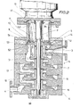
- Fig. 2 is a longitudinal sectional view showing an important portion of another example where the present invention is applied to a high pressure multi-stage volute pump.
- Fig. 3 is an enlarged expanded perspective view showing an important portion of Figs. 1 and 2, which shows the backside structure of the lst-stage impeller and the internal structure of the casing in opposite to the backside of the lst-stage impeller.
- Fig. 4 is an expanded perspective view showing the front side structure of the lst-stage impeller on the liquid suction port side.
- a casing 14 has a suction port 3 and a discharge port 4, and contains a shaft 2 supported rotatably.
- a boss 8 Around the shaft 2, a boss 8, a 3rd-stage impeller 7, a 2nd-stage impeller 6 and a 1st-stage impeller 5 are fixed in this sequence upward from the bottom with clearances.
- the shaft 2 is connected to a drive motor 1 at the top, to be driven and revolved. At the bottom end, the said boss 8 is screwed. Above it, the 3rd-stage impeller 7, 2nd-stage impeller 6 and Ist-stage impeller 5 are fitted in this sequence.
- radial flow ribs 52 are formed like curves from the center of the impeller radially toward the outside at constant intervals in the circumferential direction.
- the radial flow ribs 52 ... have a preset height.
- the protruded ring 54 is inserted in a recessed (groove) ring 10 provided on the surface of the casing 14 opposite the Ist-stage impeller 5, without any contact and with a certain gap kept, and is driven and revolved in the recessed ring (groove) 10 without any contact, according to the revolution of the shaft 2 driven by the motor 1.
- the liquid sucked from the suction port 3 is driven outward due to the centrifugal action caused by the radial flow ribs 52 ... formed on the 1st-stage impeller 5 and reaches the 2nd-stage impeller 6 through a vortex chamber 12. It is then driven outward by the centrifugal action of the 2nd-stage impeller 6 and reaches the 3rd-stage impeller 7 through a vortex chamber 13, to be further driven by its centrifugal action, thus being discharged from the discharge port 4 successively and continuously as a high pressure fluid.
- a space section 19 is formed around the shaft 2 above the lst-stage impeller 5.
- air inlets 140 and 140 are formed, to allow air to flow into the space section 19 from the inlets 140 and 140.
- the space section 19 communicates, at its bottom, to the vortex chamber 12 through the 1st-stage impeller 5.
- Fig. 2 shows another embodiment in which the present invention is applied to a multi-stage volute pump, and the same portions as in Fig. 1 are given the same symbols.
- a casing 14 is provided with a suction port 3 and a discharge port 4 for a liquid.
- the discharge port 4 is provided below the suction port 3 at the bottom of the casing 14.
- a shaft 2 driven and revolved by a motor 1 is supported vertically.
- fastening bosses 8A and 8B are screwed in, and between them, a 1st-stage-impeller 5, a 2nd-stage impeller 6, a 3rd-stage impeller 15 and a 5th-stage impeller are fitted in this sequence from above.
- the structure of the 1st-stage impeller 5 is almost the same as that shown in Figs. 3 and 4. That is, a protruded ring 54 of the lst-stage impeller is in a recessed groove 9 of the casing 14 without any contact with a constant gap kept and rotates in the recessed groove 9 according to the revolution of the shaft 2 driven by the motor 1.
- radial flow ribs 61 are formed to rise, like curves from the center of the impeller toward the outside, with intervals in the circumferential direction, to face the radial flow ribs 52 of the lst-stage impeller 5 through the suction port 3.
- the radial flow ribs 52 of the lst-stage impeller 5 and the radial flow ribs 61 of the 2nd-stage impeller 6 face each other, and the pump head increases with the increase in the number of stages.
- the liquid sucked from the suction port 3 is driven radially outward by the centrifugal action caused by the revolution of the radial flow ribs 52 provided on the lst-staae impeller 5 and by the centrifugal action caused by the planeting of the radial flow ribs 61 provided on the 2nd-stage impeller 6, and reaches the 3rd-stage impeller 7 through vortex chambers 12 and 13. It is then driven by the centrifugal action of the 3rd stage impeller 7 into a vortex chamber 7 and reaches the 4th-stage impeller 15. The liquid is further driven by the centrifugal action of the 4th-stage impeller 15, to the 5th-stage impeller 16 through a vortex chamber 18.
- the number of impellers can be increased infinitely.
- the liquid is continuously: discharged from the discharge port 4.
- the liquid seal and air leak prevention between the air suction side and the liquid suction side can be positively attained without using any special seal member. Furthermore, the present invention can be applied without any problem to either a low head high pressure cascade pump or to a high head high pressure volute pump.
Landscapes
- Engineering & Computer Science (AREA)
- Mechanical Engineering (AREA)
- General Engineering & Computer Science (AREA)
- Structures Of Non-Positive Displacement Pumps (AREA)
Applications Claiming Priority (2)
| Application Number | Priority Date | Filing Date | Title |
|---|---|---|---|
| JP155737/84 | 1984-07-26 | ||
| JP15573784A JPS6134387A (ja) | 1984-07-26 | 1984-07-26 | 高圧多段式シ−ルレスポンプ |
Publications (3)
| Publication Number | Publication Date |
|---|---|
| EP0173030A2 true EP0173030A2 (de) | 1986-03-05 |
| EP0173030A3 EP0173030A3 (en) | 1987-08-26 |
| EP0173030B1 EP0173030B1 (de) | 1990-10-10 |
Family
ID=15612340
Family Applications (1)
| Application Number | Title | Priority Date | Filing Date |
|---|---|---|---|
| EP85108145A Expired - Lifetime EP0173030B1 (de) | 1984-07-26 | 1985-07-01 | Pumpe ohne Dichtung |
Country Status (6)
| Country | Link |
|---|---|
| US (1) | US4655681A (de) |
| EP (1) | EP0173030B1 (de) |
| JP (1) | JPS6134387A (de) |
| KR (1) | KR900006403B1 (de) |
| CA (1) | CA1238520A (de) |
| DE (2) | DE173030T1 (de) |
Cited By (3)
| Publication number | Priority date | Publication date | Assignee | Title |
|---|---|---|---|---|
| DE4415566A1 (de) * | 1994-05-03 | 1995-11-09 | Sero Pumpenfabrik Gmbh | Kreiselpumpe |
| EP0867620A1 (de) * | 1997-03-24 | 1998-09-30 | Renner GmbH | Umwälzpumpe oder Rührwerk für erwärmte chemische Lösungen |
| TWI384129B (de) * | 2010-05-03 | 2013-02-01 |
Families Citing this family (21)
| Publication number | Priority date | Publication date | Assignee | Title |
|---|---|---|---|---|
| US4806080A (en) * | 1983-07-06 | 1989-02-21 | Ebara Corporation | Pump with shaftless impeller |
| JPH0197095U (de) * | 1987-12-18 | 1989-06-28 | ||
| US5358378A (en) * | 1992-11-17 | 1994-10-25 | Holscher Donald J | Multistage centrifugal compressor without seals and with axial thrust balance |
| US6034465A (en) * | 1997-08-06 | 2000-03-07 | Shurfle Pump Manufacturing Co. | Pump driven by brushless motor |
| US6132186A (en) | 1997-08-06 | 2000-10-17 | Shurflo Pump Manufacturing Co. | Impeller pump driven by a dynamo electric machine having a stator comprised of a mass of metal particles |
| US6249933B1 (en) | 1999-08-26 | 2001-06-26 | Shop Vac Corporation | Pump having sealless shaft |
| DE10004263A1 (de) * | 2000-02-01 | 2001-08-02 | Leybold Vakuum Gmbh | Dynamische Dichtung |
| JP2001329995A (ja) * | 2000-05-24 | 2001-11-30 | Ishikawajima Harima Heavy Ind Co Ltd | 可変ディフューザ付き遠心圧縮機 |
| EP1279836A1 (de) * | 2001-07-26 | 2003-01-29 | Bonferraro S.p.A. | Umsteuerbare Pumpe mit zwei Pumpenauslassen |
| KR20060039836A (ko) * | 2004-11-03 | 2006-05-09 | 강우식 | 고성능 풍, 수압 펌프 |
| EP1957800B1 (de) * | 2005-09-19 | 2010-12-29 | Ingersoll Rand Company | Antriebsrad für einen radialverdichter |
| US20070065277A1 (en) * | 2005-09-19 | 2007-03-22 | Ingersoll-Rand Company | Centrifugal compressor including a seal system |
| US20070063449A1 (en) * | 2005-09-19 | 2007-03-22 | Ingersoll-Rand Company | Stationary seal ring for a centrifugal compressor |
| WO2008085209A1 (en) * | 2006-09-08 | 2008-07-17 | Lahaye Leaon C | Apparatus and method for cleaning lumens of medical devices and lines |
| KR100868267B1 (ko) | 2008-06-09 | 2008-11-11 | 주식회사 에어젠 | 터보 블로어 |
| CN102852811B (zh) * | 2011-06-27 | 2015-08-26 | 王喜冬 | 硬质合金可空转可串联水陆两用矿用立泵 |
| CN102852812B (zh) * | 2011-06-27 | 2015-11-25 | 王喜冬 | 硬质合金可空转可串联水陆两用矿用立泵 |
| JP7202850B2 (ja) * | 2018-11-02 | 2023-01-12 | 株式会社川本製作所 | 縦型多段ポンプ |
| US11396882B2 (en) * | 2019-09-20 | 2022-07-26 | William Louis Kacin | Gas seal column pump |
| KR102115816B1 (ko) * | 2019-09-20 | 2020-05-27 | 윤홍태 | 고양정 펌프 |
| CN115949591B (zh) * | 2023-02-01 | 2023-12-08 | 广州市昕恒泵业制造有限公司 | 一种多级中开双吸离心泵 |
Citations (1)
| Publication number | Priority date | Publication date | Assignee | Title |
|---|---|---|---|---|
| DE492196C (de) | 1926-01-17 | 1930-02-20 | Basile Kamensky Dipl Ing | Mit einem die Abdichtung der Welle bewirkenden Kreiselrad versehene mehrstufige Kreiselpumpe |
Family Cites Families (16)
| Publication number | Priority date | Publication date | Assignee | Title |
|---|---|---|---|---|
| GB117558A (en) * | 1917-11-16 | 1918-07-25 | Adolf Ewald Gull | Improvement in Centrifugal Pumps. |
| US1821772A (en) * | 1926-06-04 | 1931-09-01 | Edward J Ruthman | Reversible centrifugal pump |
| US1999163A (en) * | 1929-06-04 | 1935-04-23 | Allen Sherman Hoff Co | Centrifugal pump |
| US2155452A (en) * | 1935-11-05 | 1939-04-25 | Frank E Stelzer | Pump |
| AT179275B (de) * | 1951-05-28 | 1954-08-10 | Escher Wyss Ag | Verfahren zum Fernhalten von im Betriebswasser hydraulischer Anlagen enthaltenen festen Verunreinigungen von den Labyrinth-Stopfbüschen der Maschinen solcher Anlagen |
| DE888207C (de) * | 1951-08-10 | 1953-08-31 | Siemens Ag | Selbstansaugende Pumpe |
| DE1122375B (de) * | 1960-05-10 | 1962-01-18 | Paul Bungartz | Mehrstufige Kreiselpumpe mit fliegend angeordneten Laufraedern |
| US3115097A (en) * | 1960-08-03 | 1963-12-24 | Wilfley & Sons Inc A | Corrosion resistant centrifugal pump |
| US3102680A (en) * | 1961-06-27 | 1963-09-03 | Sam F Fogleman | Multistage centrifugal gas compressor |
| US3190226A (en) * | 1963-09-13 | 1965-06-22 | Thomas E Judd | Centrifugal pumps |
| JPS5243102A (en) * | 1975-10-02 | 1977-04-04 | World Chem:Kk | Self-suction pump |
| JPS52131601U (de) * | 1975-10-25 | 1977-10-06 | ||
| SU623994A1 (ru) * | 1977-03-24 | 1978-09-15 | Предприятие П/Я А-3884 | Многоступенчатый центробежный компрессор |
| AU7989582A (en) * | 1981-01-30 | 1982-08-05 | Baker International Corp. | Centrifugal mud pump |
| US4526507A (en) * | 1982-06-14 | 1985-07-02 | Milton Roy Company | Shaft driven pump without seals |
| US4527947A (en) * | 1984-02-17 | 1985-07-09 | Elliott Eric R | Seal-free impeller pump for fluids containing abrasive materials or the like |
-
1984
- 1984-07-26 JP JP15573784A patent/JPS6134387A/ja active Granted
-
1985
- 1985-06-14 US US06/744,725 patent/US4655681A/en not_active Expired - Fee Related
- 1985-06-25 KR KR1019850004515A patent/KR900006403B1/ko not_active Expired
- 1985-06-26 CA CA000485343A patent/CA1238520A/en not_active Expired
- 1985-07-01 DE DE198585108145T patent/DE173030T1/de active Pending
- 1985-07-01 EP EP85108145A patent/EP0173030B1/de not_active Expired - Lifetime
- 1985-07-01 DE DE8585108145T patent/DE3580073D1/de not_active Expired - Fee Related
Patent Citations (1)
| Publication number | Priority date | Publication date | Assignee | Title |
|---|---|---|---|---|
| DE492196C (de) | 1926-01-17 | 1930-02-20 | Basile Kamensky Dipl Ing | Mit einem die Abdichtung der Welle bewirkenden Kreiselrad versehene mehrstufige Kreiselpumpe |
Cited By (4)
| Publication number | Priority date | Publication date | Assignee | Title |
|---|---|---|---|---|
| DE4415566A1 (de) * | 1994-05-03 | 1995-11-09 | Sero Pumpenfabrik Gmbh | Kreiselpumpe |
| DE4415566C2 (de) * | 1994-05-03 | 1999-02-18 | Sero Pumpenfabrik Gmbh | Seitenkanalpumpe |
| EP0867620A1 (de) * | 1997-03-24 | 1998-09-30 | Renner GmbH | Umwälzpumpe oder Rührwerk für erwärmte chemische Lösungen |
| TWI384129B (de) * | 2010-05-03 | 2013-02-01 |
Also Published As
| Publication number | Publication date |
|---|---|
| DE173030T1 (de) | 1986-08-14 |
| US4655681A (en) | 1987-04-07 |
| DE3580073D1 (de) | 1990-11-15 |
| EP0173030A3 (en) | 1987-08-26 |
| KR860001300A (ko) | 1986-02-24 |
| JPH0468480B2 (de) | 1992-11-02 |
| CA1238520A (en) | 1988-06-28 |
| EP0173030B1 (de) | 1990-10-10 |
| JPS6134387A (ja) | 1986-02-18 |
| KR900006403B1 (ko) | 1990-08-30 |
Similar Documents
| Publication | Publication Date | Title |
|---|---|---|
| EP0173030A2 (de) | Pumpe ohne Dichtung | |
| US5158440A (en) | Integrated centrifugal pump and motor | |
| US3265001A (en) | Centrifugal pump | |
| US5490763A (en) | Pump for shear sensitive fluids | |
| US3116696A (en) | Centrifugal pump | |
| US3123010A (en) | Centrifugal pump with thrust balancing means | |
| JPS63277900A (ja) | 遠心ポンプ用推進器 | |
| CN1131978A (zh) | 磨损小的涡轮机 | |
| CN101371047B (zh) | 用于转子动力泵的挠性浮动环密封装置 | |
| KR940021938A (ko) | 웨스트코형 펌프 | |
| GB2290113A (en) | Centrifugal pump shaft seal cooling and venting | |
| US11493053B2 (en) | Pump for conveying a fluid | |
| KR920018356A (ko) | 임펠러 환상(環狀)실(seal) | |
| US3040670A (en) | Pumps | |
| JP2546943B2 (ja) | 一体形遠心ポンプとモータ | |
| US2319776A (en) | Rotary pump | |
| US2781209A (en) | Dynamic seal for a centrifugal pump | |
| EP0380990A2 (de) | Umsteuerbare Kreiselpumpe | |
| US5071317A (en) | Centrifugal pump having a unitary one-piece diffusion casing and a unitary one piece turbine impeller unit | |
| US1065732A (en) | Centrifugal pump. | |
| KR102738215B1 (ko) | 공동공간 내에 이물질 침투를 방지하는 리어윙을 구비한 입축 또는 수중 펌프 | |
| KR0181398B1 (ko) | 펌프의 씰링장치 | |
| KR100469683B1 (ko) | 케미칼 프로세스 펌프 | |
| KR100917250B1 (ko) | 축추력 자동조절을 위한 벨로우즈장치를 구비한 터보기계 | |
| JPH085358Y2 (ja) | ガスシール型モータポンプ装置 |
Legal Events
| Date | Code | Title | Description |
|---|---|---|---|
| PUAI | Public reference made under article 153(3) epc to a published international application that has entered the european phase |
Free format text: ORIGINAL CODE: 0009012 |
|
| AK | Designated contracting states |
Kind code of ref document: A2 Designated state(s): DE FR GB IT |
|
| ITCL | It: translation for ep claims filed |
Representative=s name: STUDIO G.L.P. SAS PETRAZ GILBERTO |
|
| EL | Fr: translation of claims filed | ||
| DET | De: translation of patent claims | ||
| PUAL | Search report despatched |
Free format text: ORIGINAL CODE: 0009013 |
|
| AK | Designated contracting states |
Kind code of ref document: A3 Designated state(s): DE FR GB IT |
|
| 17P | Request for examination filed |
Effective date: 19880105 |
|
| 17Q | First examination report despatched |
Effective date: 19890216 |
|
| GRAA | (expected) grant |
Free format text: ORIGINAL CODE: 0009210 |
|
| AK | Designated contracting states |
Kind code of ref document: B1 Designated state(s): DE FR GB IT |
|
| REF | Corresponds to: |
Ref document number: 3580073 Country of ref document: DE Date of ref document: 19901115 |
|
| ITF | It: translation for a ep patent filed | ||
| ET | Fr: translation filed | ||
| ITTA | It: last paid annual fee | ||
| PLBE | No opposition filed within time limit |
Free format text: ORIGINAL CODE: 0009261 |
|
| STAA | Information on the status of an ep patent application or granted ep patent |
Free format text: STATUS: NO OPPOSITION FILED WITHIN TIME LIMIT |
|
| 26N | No opposition filed | ||
| PGFP | Annual fee paid to national office [announced via postgrant information from national office to epo] |
Ref country code: GB Payment date: 19930622 Year of fee payment: 9 |
|
| PGFP | Annual fee paid to national office [announced via postgrant information from national office to epo] |
Ref country code: FR Payment date: 19930721 Year of fee payment: 9 |
|
| PGFP | Annual fee paid to national office [announced via postgrant information from national office to epo] |
Ref country code: DE Payment date: 19930830 Year of fee payment: 9 |
|
| PG25 | Lapsed in a contracting state [announced via postgrant information from national office to epo] |
Ref country code: GB Effective date: 19940701 |
|
| GBPC | Gb: european patent ceased through non-payment of renewal fee |
Effective date: 19940701 |
|
| PG25 | Lapsed in a contracting state [announced via postgrant information from national office to epo] |
Ref country code: FR Effective date: 19950331 |
|
| PG25 | Lapsed in a contracting state [announced via postgrant information from national office to epo] |
Ref country code: DE Effective date: 19950401 |
|
| REG | Reference to a national code |
Ref country code: FR Ref legal event code: ST |