EP0173046A1 - Dispositif de protection de plantes forestières - Google Patents
Dispositif de protection de plantes forestières Download PDFInfo
- Publication number
- EP0173046A1 EP0173046A1 EP85108731A EP85108731A EP0173046A1 EP 0173046 A1 EP0173046 A1 EP 0173046A1 EP 85108731 A EP85108731 A EP 85108731A EP 85108731 A EP85108731 A EP 85108731A EP 0173046 A1 EP0173046 A1 EP 0173046A1
- Authority
- EP
- European Patent Office
- Prior art keywords
- protection device
- hood
- plant protection
- lattice
- parts
- Prior art date
- Legal status (The legal status is an assumption and is not a legal conclusion. Google has not performed a legal analysis and makes no representation as to the accuracy of the status listed.)
- Granted
Links
- 230000001012 protector Effects 0.000 title description 9
- 239000002184 metal Substances 0.000 claims description 4
- 229910052751 metal Inorganic materials 0.000 claims description 4
- 241000196324 Embryophyta Species 0.000 description 41
- XEEYBQQBJWHFJM-UHFFFAOYSA-N Iron Chemical compound [Fe] XEEYBQQBJWHFJM-UHFFFAOYSA-N 0.000 description 10
- 238000005452 bending Methods 0.000 description 6
- 229910052742 iron Inorganic materials 0.000 description 5
- 230000001681 protective effect Effects 0.000 description 5
- 238000010276 construction Methods 0.000 description 4
- 230000006378 damage Effects 0.000 description 4
- 238000003860 storage Methods 0.000 description 4
- 238000004804 winding Methods 0.000 description 4
- 238000003780 insertion Methods 0.000 description 3
- 230000037431 insertion Effects 0.000 description 3
- 238000009434 installation Methods 0.000 description 3
- 238000003801 milling Methods 0.000 description 3
- 241000282994 Cervidae Species 0.000 description 2
- 229910000831 Steel Inorganic materials 0.000 description 2
- 238000001514 detection method Methods 0.000 description 2
- 210000005069 ears Anatomy 0.000 description 2
- 238000012423 maintenance Methods 0.000 description 2
- 238000004519 manufacturing process Methods 0.000 description 2
- 239000010959 steel Substances 0.000 description 2
- 239000004575 stone Substances 0.000 description 2
- 241001465754 Metazoa Species 0.000 description 1
- 229910000746 Structural steel Inorganic materials 0.000 description 1
- 208000027418 Wounds and injury Diseases 0.000 description 1
- 238000004873 anchoring Methods 0.000 description 1
- 230000015572 biosynthetic process Effects 0.000 description 1
- 238000011161 development Methods 0.000 description 1
- 230000018109 developmental process Effects 0.000 description 1
- 208000014674 injury Diseases 0.000 description 1
- 238000009304 pastoral farming Methods 0.000 description 1
- 230000001105 regulatory effect Effects 0.000 description 1
- 238000005096 rolling process Methods 0.000 description 1
- 230000006641 stabilisation Effects 0.000 description 1
- 238000011105 stabilization Methods 0.000 description 1
- 238000009333 weeding Methods 0.000 description 1
Images



Classifications
-
- A—HUMAN NECESSITIES
- A01—AGRICULTURE; FORESTRY; ANIMAL HUSBANDRY; HUNTING; TRAPPING; FISHING
- A01G—HORTICULTURE; CULTIVATION OF VEGETABLES, FLOWERS, RICE, FRUIT, VINES, HOPS OR SEAWEED; FORESTRY; WATERING
- A01G13/00—Protection of plants
- A01G13/20—Protective coverings for plants
- A01G13/28—Protective coverings for plants protecting young plants
Definitions
- the invention relates to a plant protection device according to the preamble of claim 1.
- plant protection devices are used in particular as tree protectors in forest crops to protect against bite by wild animals and the disruption of young plants.
- wire pants can be used to protect the young plants, which are placed around the plant and cramped on a wooden stake. If necessary, several pegs are also hammered in, which leads to a small fence around the young plant.
- Wired pants have the advantage over fences that the grazing area between the plants remains free for the game and that falling trees do less damage. Compared to the planting with hay, the taproot formation is ensured.
- the conventional wire pants have a considerable assembly time, the assembly and later dismantling are time-consuming and therefore cost-intensive. They also do not technically fully meet the requirements because, on the one hand, they are not stable; the wooden posts are lifted out by frost or rot over time.
- the wire pants themselves can be deformed, e.g. B. by snow on a slope, and then only imperfectly protects the plant.
- Small plants can be suffocated by weeds that grow in the wire pants, where they are not cut off by the game and are difficult to remove by hand.
- wire pants can grow out laterally through wire mesh and can hardly be retrieved without damage.
- wire pants When the wire pants are disassembled, when the plant has grown large, it is cut up, which prevents reuse, or it is pulled over the ears of the plant, which can damage the plant.
- a known tree protector (DE-PS 130902) consists of a wire spiral which is pulled apart into a cone and placed over the tree, which essentially carries its weight. A side support is inserted into the floor for stabilization. The tree can easily be damaged both when this wire spiral is put on and when the tree protector is too heavy, for example due to wet leaves, snow etc. The top must grow out to the side.
- Another known tree protector (DE-PS 814071) consists of a grid that sits on two short stakes and is inelastically bent around the tree. Such a tree protector can be gently placed around the tree, but due to its weak anchoring and easy bendability, it offers insufficient protection. It has an inflexible segment between the pegs. If a stake could be driven into the ground while the other hit a stone or a root, the entire installation had to be loosened and repositioned with the risk of bending.
- protective sleeves for protecting tree trunks are known (DE-OS 2231875), which are cut open along a surface line and can be resiliently bent apart so that they can be placed around the trunk. Such pods, however, are less suitable for protecting young forest plants.
- the invention has for its object to provide a crop protection device that has the properties of easy assembly and disassembly, low maintenance and damage-free crop protection combined.
- This object is achieved by the invention characterized in claim 1.
- This design creates a completely prefabricable plant protection device, the protective grille in the form of the grille of the plant does not have to be pulled "over the ears" during construction or dismantling, but is placed around it in a gentle manner and by re-opening all or part of it Detection of the top or individual branches can be easily adjusted.
- the one stake which must be insertable deep enough in the ground to provide the required support, results in the only fixed line of the lattice hood, so that there is no obstacle to the bending along the circumference of the hood and also the dependence on insertion obstacles in the ground, such as stones, is low.
- a special design is a resiliently bendable lattice hood, z.
- B. a known (DE-PS 130902) conical shape or a multi-part design come into question.
- the parts can be circumferentially or axially separated, the latter approximately according to claim 3, ie with pants and jacket, a lower conical part being called pants and an upper cylindrical part being called a jacket.
- the requirements can be adapted even more precisely to the respective plant, in particular the tree protector can still be used even after a long summit shoot has been pushed and its protective effect can be developed.
- This axially two-part design requires a somewhat higher outlay for production and storage.
- a helical design in particular made of wire, can be used, which is cut open along the open gap.
- the lattice hood may consist of ring-shaped or semi-ring-shaped sheet metal strips, each ending at the gap and lying vertically in its sheet metal plane or running in the cone surface, which can be resiliently bent outwards. If the wires or sheet metal strips end individually at the gap, the individual wire or strip can be bent outwards at any height. This can be useful, for example, for regulating the position of individual shoots or branches, but on the other hand leads to sharp edges or tips which are undesirable because of the risk of injury.
- the gap can be delimited by edge strips which are connected to the individual lattice bars or wires coming up to the gap.
- edge strips which are connected to the individual lattice bars or wires coming up to the gap.
- the halves of the lattice hood connected by these edge strips can only be bent up or spring back again as a whole.
- the construction of the lattice expediently looks such that the individual windings or rings of the lattice hood have a back line along an axis-parallel line at which there are points for connection to the stake. If the gap is not lined with edge strips that hold the individual resilient windings or rings together, or other grating options are provided, the back line in the form of a rod attached to the windings or rings also fulfills the purpose of mutual connection and thus the grating of the individual hood elements.
- Preferred forms of the lattice hood are those with circular horizontal sections which enable the plant to develop in all directions, those with oval horizontal sections for cases in which the stake is to be inserted at a greater distance from the plant base, or polygonal cross sections which are light and stable Allow stacking of circumferentially divided grid parts called.
- a crop protection device which combines the properties of easy assembly and disassembly, low maintenance, damage-free crop protection and space-saving storage.
- This design creates a plant protection device, the protective grille of which is put together in the form of the lattice hood and is placed gently around the plant, and if necessary, can be easily adjusted with respect to the detection of the tree top or individual branches by opening all or part of it again.
- the individual parts require considerably less volume than the total volume of the eventual tubular shape of the lattice hood, in particular the parts can be stacked, which is very important for larger forest areas because of the often required large number of pieces.
- the longitudinal lines are surface lines, but they can also be oblique lines, zigzag lines or the like with a longitudinal component.
- the lattice hood can be composed of two parts, but for larger or specially designed lattice hoods, a different number of parts, for example three, can also be advantageous in order to achieve stackable parts.
- the parts are, based on the general tube shape, preferably tubular segments.
- two parts are present, the connection of which is carried out along the one longitudinal line through the mutual attachment to the stake.
- the other longitudinal line can be accomplished according to claim 12 by connecting tabs approximately in the form of brackets or clips.
- the measure according to claim 13 has the advantage that only a single version of the part has to be kept ready, the grille hood can be assembled from two or possibly more than two ellipses of this version.
- the stackability and handling is also improved by the prism or pyramid shape according to claim 16.
- the lattice hood and / or on the peg at different heights, so that the lattice hood or the parts of the lattice hood can be attached to the peg at variable heights.
- a protective device that grows with the growth of the young tree by adjusting the height over several years.
- the height variability can be achieved relatively easily by means of fastening points in the form of milled portions and fastening tabs or in the form of incisions for inserting wire mesh, so that the mesh meshes result in the adjustability grid.
- This height adjustability is particularly useful when the stake has a defined insertion depth, which can be determined with the aid of a footrest that makes insertion easier.
- the stake is not quite he has sunk or has lifted himself out a bit again, this is immediately visible and can be remedied by stepping in with the footrest.
- the measure according to claim 18 keeps the plant protection device secured against twisting, so that no significant lateral forces exerted by the grille hood, which can lead to bent growth, act on the plant.
- the detachability of the lattice hood from the stake in particular the possibility of quickly dismantling and reassembling without tools or, if necessary, using a pair of pliers, also allows the lattice hood to be temporarily removed, for example when weeding out or during felling and rear working.
- the additional grid parts according to claim 19 prevent a bite by deer from above.
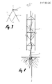
- the plant protection device according to FIG. 1, which is to be used as a tree protector, consists of a lattice hood 1 and a peg 2 which are detachably connected to one another at fastening points 3.
- the lattice hood 1 consists of two parts 4 and 5 in the form of curved wire mesh fields made of wire with a diameter of 3 mm and possibly somewhat thicker wire along axis-parallel longitudinal lines 6 and 7, on which the two parts of the lattice hood are detachably connected to one another to form them.
- the grid hood shown has meshes in the form of horizontal hexagon rings, which are connected at the corners by vertical wires. With eleven rings at a distance of 7 cm, the total height is 70 cm.
- the lattice hood 1 has the overall shape of a hexagonal prism, each of the parts 4 and 5 comprises three surfaces of this prism.
- Wires 8 and 9 are welded to the hexagonal top of the lattice hood, in each case between the end hexagon edges of the individual part 4 and 5, respectively, which prevent a deer bite of the plant from above.
- the two parts 4 and 5 can be completely identical in shape, a single stack of such parts can be piled up for storage and transport. It must then be easily interchangeable for both parts 4 and 5 above and below and / or right and left. In the embodiment shown in FIG. 1, this form identity is only available with reservations. As far as described so far, the parts 4 and 5 are identical in form insofar as they are interchangeable from left to right, but because of the wires 8 and 9 they are not interchangeable from top to bottom.
- this has welded-on, partly incised sheets 10 which leave a total of four incision surfaces 11 and which each protrude on one side of the peg in the hexagonal cross-sectional area of the lattice hood.
- the incision surfaces 11 have an L shape and have a mutual height spacing that is matched to the grid pattern.
- the two parts 4 and 5 can each be inserted into one of the L-shaped incision surfaces 11 with adjacent, horizontally running wires.
- a hold on the sheets 10 is possible by this or the wires resiliently bending so that the hold of the mesh hood 1 results not only from its own weight, but also from the friction of the wire on the surfaces.
- the grille hood cannot be lifted out of the holder by external forces.
- the sheet is temporarily straightened again.
- the grille hood 1 on the sheets 10 can be adjusted in height in seven stages in accordance with the grid of the wire rings. The elasticity of the sheet enables parts 4 and 5 to be pivoted to a certain extent during assembly.
- the longitudinal line 7 forms a gap between the parts 4 and 5, is bridged by means of clip-like fastening tabs 12 which hold the parts 4 and 5 together.
- These mounting brackets can be attached or, depending on the construction, attached like clips. So that small parts do not have to be kept loose when working in the forest, according to a special embodiment the fastening tabs are attached to one of the parts 4, 5 from the outset and are then only hooked to the other of these parts. It is either possible to have fastening tabs along the longitudinal line 6 on the peg side, where they are actually not required; parts 4 and 5 can then be identical. Or only one of the parts is pre-equipped with the fastening tabs 12, as a result of which the parts 4 and 5 differ from one another and are to be stacked separately or alternately.
- the peg 2 consists of a round iron pointed at the bottom, to which a footrest 2a is welded at a height which, when the peg is inserted, corresponds to the earth level. This footrest can be used to enter the stake, so that this is essentially possible without tools.
- a mandrel 2b pointed at the bottom, which, like the foot part of the peg 2, penetrates into the ground when entering and thus protects the mon
- the plant protection device acts.
- the peg 2 is first penetrated so deep into the ground using the footrest 2a that the peg 2a welded to the peg 2 rests on the ground.
- the footrest 8 thus both facilitates driving in and also sets a height mark.
- the incision surfaces 11 thus have a defined height above the ground, to which the height of the mesh hood 1 is matched.
- An attachment with a lower free space of 20 cm is sufficient for the game protection and allows weed removal without removing the grille hood.
- the stability of the stake and the stiffness of the wire withstand normal deformation loads such as lateral snow pressure.
- FIGS. 3 and 4 Another, somewhat more complex form of the crop protection device is shown in FIGS. 3 and 4. It consists of three detachably connected parts, namely the peg 2 and a two-part lattice hood 1, which in turn consists of trousers 13 and a jacket 14.
- the pants are flared downwards, the jacket 14 has a substantially cylindrical configuration.
- the trousers 13 and the jacket 14 consist of curved strips 15 made of galvanized sheet steel of 1 mm thickness, which are each welded to a profiled iron forming a back line 16. On this profile iron sits a fastening tab 17 in the manner of a clip fastener for the trousers 13 and the jacket 14.
- the peg 2 is 1.40 m long and consists of 3 mm angle iron. At 0.5 m from below, a footrest 18 corresponding to the footrest 2a is welded on. The stake also has three milled portions 19 at different heights.
- the fastening tab 17 of the jacket 14 is mounted asymmetrically in relation to its height, so that, taking into account the two possible mounting positions of the jacket on the one hand and the two millings 19 available on the peg 12 on the other hand, the jacket 14 can be attached at four different heights.
- the trousers 13 and the jacket 14 can be used together or one of the two can be satisfied. Both parts have a gap 20 from which they can be bent open. The strips on both sides can also overlap by a bit in the idle state, so that the gap has a partially circumferential course.
- This version also allows quick assembly and disassembly without tools and results in high stability. It allows the jacket and pants to be bent apart to the side without damaging branches. When dismantling, the parts are not pulled upwards from the grown plant, but are laterally removed by bending them open. The protection device can then be reused elsewhere.
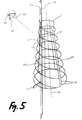
- the plant protection device according to Figure 5 is again in two parts executed and consists of the lattice hood 1 and the peg 2, which are detachably connected to each other at the attachment point 3.
- the lattice hood 1 here consists of a conical wire pants, the wire with a 3 mm diameter of which runs along a helical line which increases in diameter from top to bottom, but which is interrupted along a surface line by a gap 24.
- the individual windings of the wire screw are cut open along the gap 24 and connected, for example welded, to respective limiting wires 25.
- This back line consists of strong wire with a diameter of 4 mm, to which each of the turns of the wire screw and also a horizontal cover turn and a horizontal base turn are welded.
- a fastening tab 27 hangs at a given height, which serves to fasten the lattice hood 1 to the peg 2 in the manner shown in FIG. 5 and its secondary figure.
- the peg 2 which consists of an L-profile iron with a leg width of 2 cm, has, in accordance with the peg according to FIG. 3, the welded-on footrest 18 and the two millings 19.
- the millings 19 are spaced apart along the length of the stake 2. and serve to hook in the fastening tab 27, whereby the grille hood can be locked in two different height positions on the stake. While the height of the stake is about 1.50 m, the lattice hood 1 is about 70 cm high.
- the envelope of the grille hood forms a truncated cone, the axis of which is designated 28.
- FIGS. 6 to 8 show a plant protection device which can serve, in particular, as protection against bucking of young plants by roebucks.
- the lattice hood 1 here consists of a triangular wire prism, the longitudinal edges of which are on the one hand by the peg 2 and on the other hand by two 4 mm thick longitudinal rods 31 be made of steel.
- the stake 2 itself in this embodiment consists of an above-ground rod 32 of 8 mm thickness and a somewhat stronger underground part 33 of building iron of 8 to 10 mm thickness, which can be entered into the ground even in the presence of lighter obstacles.
- the stake in turn has the footrest 2a and the mandrel 2b.
- the bars 31 and 32 are arranged vertically, while horizontally grid wires 34 of 2.2 mm thickness run, which are welded to the bars 31 and 32.
- horizontally grid wires 34 of 2.2 mm thickness run, which are welded to the bars 31 and 32.
- there are three such grid wires 34 which practically form three intermediate levels at two equal distances.
- the crop protection device can be supplied in the flat form shown in Fig. 6 and is folded up during installation. If it is folded into an equilateral prism, the free ends of the grid wires 34 projecting from the rods 31 overlap. However, in order to surround a somewhat more lush plant, the plant protection device can also be folded into a somewhat larger plan, which can also have a square shape, by the free wire ends are not towards the adjacent longitudinal rod 31, but are bent outward at an angle. This creates a kind of square prism, but no longer runs along its fourth edge. Since the plant protection device is only anchored in the ground with a single stake, there are no rigid restrictions on folding from both sides around the plant.
- the length of the peg 2 in its underground part 3 and the robustness of the part result in an easy installation for the crop protection device on the one hand and a very stable stand on the other hand, which even gives the plant a support.
Landscapes
- Health & Medical Sciences (AREA)
- General Health & Medical Sciences (AREA)
- Toxicology (AREA)
- Life Sciences & Earth Sciences (AREA)
- Environmental Sciences (AREA)
- Protection Of Plants (AREA)
- Catching Or Destruction (AREA)
Priority Applications (1)
| Application Number | Priority Date | Filing Date | Title |
|---|---|---|---|
| AT85108731T ATE55534T1 (de) | 1984-08-17 | 1985-07-12 | Forstpflanzenschutzvorrichtung. |
Applications Claiming Priority (4)
| Application Number | Priority Date | Filing Date | Title |
|---|---|---|---|
| DE8424459U | 1984-08-17 | ||
| DE19848424459 DE8424459U1 (de) | 1984-08-17 | 1984-08-17 | Pflanzenschutzvorrichtung |
| DE19848436406 DE8436406U1 (de) | 1984-12-12 | 1984-12-12 | Pflanzenschutzvorrichtung |
| DE8436406U | 1984-12-12 |
Publications (2)
| Publication Number | Publication Date |
|---|---|
| EP0173046A1 true EP0173046A1 (fr) | 1986-03-05 |
| EP0173046B1 EP0173046B1 (fr) | 1990-08-16 |
Family
ID=25950012
Family Applications (1)
| Application Number | Title | Priority Date | Filing Date |
|---|---|---|---|
| EP85108731A Expired - Lifetime EP0173046B1 (fr) | 1984-08-17 | 1985-07-12 | Dispositif de protection de plantes forestières |
Country Status (2)
| Country | Link |
|---|---|
| EP (1) | EP0173046B1 (fr) |
| DE (1) | DE3579201D1 (fr) |
Cited By (4)
| Publication number | Priority date | Publication date | Assignee | Title |
|---|---|---|---|---|
| WO2009051500A1 (fr) * | 2007-10-10 | 2009-04-23 | Mark Edward Bloxwich | Moyens de protection pour arbres et autres plantes |
| EP2368422A3 (fr) * | 2010-03-22 | 2013-10-16 | Peter Witasek | Dispositif phytosanitaire |
| EP2875722A1 (fr) * | 2013-11-26 | 2015-05-27 | Bidault, Stéphane | Tuteur pour plant de vigne |
| AT522592A4 (de) * | 2019-07-11 | 2020-12-15 | Josef Pamminger | Fegeschutzvorrichtung |
Citations (9)
| Publication number | Priority date | Publication date | Assignee | Title |
|---|---|---|---|---|
| FR432099A (fr) * | 1911-07-10 | 1911-11-28 | Heinrich Brauer | Dispositif de protection pour arbres fruitiers |
| GB149102A (en) * | 1919-05-27 | 1920-08-12 | George Henry Tonks | A novel or improved device for use when moulding up celery and the like |
| CH126736A (fr) * | 1927-08-30 | 1928-07-02 | Gerard Erismann | Appareil paragrêle pour cep de vigne. |
| US1790259A (en) * | 1927-08-11 | 1931-01-27 | Gertrude R Bush | Vegetation-preserving device |
| US2056136A (en) * | 1936-05-20 | 1936-09-29 | American Steel & Wire Co | Horticultural guard |
| DE814071C (de) * | 1950-09-05 | 1951-09-20 | Hans-Heinrich Hallensleben | Vorrichtung zum Schutz von Pflanzen gegen Wild- o. dgl. Verbiss |
| CH361691A (de) * | 1958-07-19 | 1962-04-30 | Dinkel Edwin | Schutzvorrichtung für Jungholz |
| US3397485A (en) * | 1967-11-30 | 1968-08-20 | Eastern Tool & Mfg Co | Plant stake |
| DE7300811U (de) * | 1973-05-10 | Koeglmeier W | Vogelfraß-Schutzabdeckung |
-
1985
- 1985-07-12 DE DE8585108731T patent/DE3579201D1/de not_active Expired - Lifetime
- 1985-07-12 EP EP85108731A patent/EP0173046B1/fr not_active Expired - Lifetime
Patent Citations (9)
| Publication number | Priority date | Publication date | Assignee | Title |
|---|---|---|---|---|
| DE7300811U (de) * | 1973-05-10 | Koeglmeier W | Vogelfraß-Schutzabdeckung | |
| FR432099A (fr) * | 1911-07-10 | 1911-11-28 | Heinrich Brauer | Dispositif de protection pour arbres fruitiers |
| GB149102A (en) * | 1919-05-27 | 1920-08-12 | George Henry Tonks | A novel or improved device for use when moulding up celery and the like |
| US1790259A (en) * | 1927-08-11 | 1931-01-27 | Gertrude R Bush | Vegetation-preserving device |
| CH126736A (fr) * | 1927-08-30 | 1928-07-02 | Gerard Erismann | Appareil paragrêle pour cep de vigne. |
| US2056136A (en) * | 1936-05-20 | 1936-09-29 | American Steel & Wire Co | Horticultural guard |
| DE814071C (de) * | 1950-09-05 | 1951-09-20 | Hans-Heinrich Hallensleben | Vorrichtung zum Schutz von Pflanzen gegen Wild- o. dgl. Verbiss |
| CH361691A (de) * | 1958-07-19 | 1962-04-30 | Dinkel Edwin | Schutzvorrichtung für Jungholz |
| US3397485A (en) * | 1967-11-30 | 1968-08-20 | Eastern Tool & Mfg Co | Plant stake |
Cited By (6)
| Publication number | Priority date | Publication date | Assignee | Title |
|---|---|---|---|---|
| WO2009051500A1 (fr) * | 2007-10-10 | 2009-04-23 | Mark Edward Bloxwich | Moyens de protection pour arbres et autres plantes |
| EP2368422A3 (fr) * | 2010-03-22 | 2013-10-16 | Peter Witasek | Dispositif phytosanitaire |
| EP2875722A1 (fr) * | 2013-11-26 | 2015-05-27 | Bidault, Stéphane | Tuteur pour plant de vigne |
| FR3013558A1 (fr) * | 2013-11-26 | 2015-05-29 | Stephane Bidault | Tuteur pour plant de vigne |
| AT522592A4 (de) * | 2019-07-11 | 2020-12-15 | Josef Pamminger | Fegeschutzvorrichtung |
| AT522592B1 (de) * | 2019-07-11 | 2020-12-15 | Josef Pamminger | Fegeschutzvorrichtung |
Also Published As
| Publication number | Publication date |
|---|---|
| DE3579201D1 (de) | 1990-09-20 |
| EP0173046B1 (fr) | 1990-08-16 |
Similar Documents
| Publication | Publication Date | Title |
|---|---|---|
| EP0243376B1 (fr) | Dispositif de fixation d'objets en forme de barres, en particulier des poteaux, dans le sol | |
| DE69624941T2 (de) | Pflanzenschutz | |
| DE1059233B (de) | Hindernis zur Abwehr von Tieren | |
| EP2368422B1 (fr) | Dispositif de protection de plantes | |
| DE3739947C1 (de) | Pflanzenstuetzkorb | |
| EP1232684B1 (fr) | Piquet profilé en tôle laminée pour la culture de la vigne ou des fruits | |
| EP0173046B1 (fr) | Dispositif de protection de plantes forestières | |
| DE7910656U1 (de) | Gestaenge fuer zelte oder gewoelbte raeume | |
| EP0227718B1 (fr) | Capuchon protecteur pour la culture de plants, notamment de plants de tomates | |
| DE3522140A1 (de) | Pfahlartige halterung fuer netze, planen, folien od. dgl. bespannungen | |
| DE102020004880B4 (de) | Pfosten für Spalieranlagen | |
| DE202022100808U1 (de) | Wuchshülle | |
| DE102010011641B3 (de) | Vorrichtung zum Stützen und Halten von Pflanzen | |
| DE3912821C1 (en) | Metal protective cage for tree - has horizontal tie rods bent into V- or U-shape | |
| EP3195722A1 (fr) | Piquet pour la viticulture | |
| DE102009019152B4 (de) | Verfahren zur Aufzucht von Junggehölzsetzlingen und Einrichtung zur Durchführung des Verfahrens | |
| EP1982579B1 (fr) | Piquet de tête | |
| DE8424459U1 (de) | Pflanzenschutzvorrichtung | |
| DE60100769T2 (de) | Zaun für Umzäunung oder Plantage | |
| DE8436406U1 (de) | Pflanzenschutzvorrichtung | |
| DE818137C (de) | Stuetzstab fuer Pflanzen | |
| DE102010048452B3 (de) | Mobile Auffangvorrichtung und Verfahren zum Einsatz der Auffangvorrichtung | |
| AT162008B (de) | Baumschutz gegen Wildschaden. | |
| DE19949790A1 (de) | Schutzvorrichtung vor Wildverbiss- und Fegeschäden bei Bäumen | |
| CH638077A5 (en) | Support device for plants which grow vertically |
Legal Events
| Date | Code | Title | Description |
|---|---|---|---|
| PUAI | Public reference made under article 153(3) epc to a published international application that has entered the european phase |
Free format text: ORIGINAL CODE: 0009012 |
|
| AK | Designated contracting states |
Kind code of ref document: A1 Designated state(s): AT CH DE FR LI |
|
| 17P | Request for examination filed |
Effective date: 19860828 |
|
| 17Q | First examination report despatched |
Effective date: 19880428 |
|
| GRAA | (expected) grant |
Free format text: ORIGINAL CODE: 0009210 |
|
| AK | Designated contracting states |
Kind code of ref document: B1 Designated state(s): AT CH DE FR LI |
|
| PG25 | Lapsed in a contracting state [announced via postgrant information from national office to epo] |
Ref country code: FR Effective date: 19900816 |
|
| REF | Corresponds to: |
Ref document number: 55534 Country of ref document: AT Date of ref document: 19900915 Kind code of ref document: T |
|
| REF | Corresponds to: |
Ref document number: 3579201 Country of ref document: DE Date of ref document: 19900920 |
|
| EN | Fr: translation not filed | ||
| PLBE | No opposition filed within time limit |
Free format text: ORIGINAL CODE: 0009261 |
|
| STAA | Information on the status of an ep patent application or granted ep patent |
Free format text: STATUS: NO OPPOSITION FILED WITHIN TIME LIMIT |
|
| 26N | No opposition filed | ||
| PGFP | Annual fee paid to national office [announced via postgrant information from national office to epo] |
Ref country code: CH Payment date: 19950719 Year of fee payment: 11 |
|
| PGFP | Annual fee paid to national office [announced via postgrant information from national office to epo] |
Ref country code: AT Payment date: 19950721 Year of fee payment: 11 |
|
| PG25 | Lapsed in a contracting state [announced via postgrant information from national office to epo] |
Ref country code: AT Effective date: 19960712 |
|
| PG25 | Lapsed in a contracting state [announced via postgrant information from national office to epo] |
Ref country code: LI Effective date: 19960731 Ref country code: CH Effective date: 19960731 |
|
| REG | Reference to a national code |
Ref country code: CH Ref legal event code: PL |
|
| PGFP | Annual fee paid to national office [announced via postgrant information from national office to epo] |
Ref country code: DE Payment date: 19970730 Year of fee payment: 13 |
|
| PG25 | Lapsed in a contracting state [announced via postgrant information from national office to epo] |
Ref country code: DE Free format text: LAPSE BECAUSE OF NON-PAYMENT OF DUE FEES Effective date: 19990501 |