EP0173080A2 - Roue de véhicule - Google Patents
Roue de véhicule Download PDFInfo
- Publication number
- EP0173080A2 EP0173080A2 EP85109359A EP85109359A EP0173080A2 EP 0173080 A2 EP0173080 A2 EP 0173080A2 EP 85109359 A EP85109359 A EP 85109359A EP 85109359 A EP85109359 A EP 85109359A EP 0173080 A2 EP0173080 A2 EP 0173080A2
- Authority
- EP
- European Patent Office
- Prior art keywords
- tire
- tread
- beads
- vehicle wheel
- belt
- Prior art date
- Legal status (The legal status is an assumption and is not a legal conclusion. Google has not performed a legal analysis and makes no representation as to the accuracy of the status listed.)
- Ceased
Links
- 239000011324 bead Substances 0.000 claims abstract description 27
- 230000007935 neutral effect Effects 0.000 claims abstract description 8
- 239000012528 membrane Substances 0.000 claims abstract description 4
- 238000013016 damping Methods 0.000 claims description 4
- 150000001875 compounds Chemical class 0.000 claims description 2
- 238000005096 rolling process Methods 0.000 abstract description 3
- 235000019589 hardness Nutrition 0.000 description 2
- 230000002787 reinforcement Effects 0.000 description 2
- 238000005299 abrasion Methods 0.000 description 1
- 230000001133 acceleration Effects 0.000 description 1
- 230000006835 compression Effects 0.000 description 1
- 238000007906 compression Methods 0.000 description 1
- 230000000694 effects Effects 0.000 description 1
- 239000000463 material Substances 0.000 description 1
- 239000000203 mixture Substances 0.000 description 1
- 239000004033 plastic Substances 0.000 description 1
- 229920003023 plastic Polymers 0.000 description 1
- 239000000725 suspension Substances 0.000 description 1
Images
Classifications
-
- B—PERFORMING OPERATIONS; TRANSPORTING
- B60—VEHICLES IN GENERAL
- B60C—VEHICLE TYRES; TYRE INFLATION; TYRE CHANGING; CONNECTING VALVES TO INFLATABLE ELASTIC BODIES IN GENERAL; DEVICES OR ARRANGEMENTS RELATED TO TYRES
- B60C9/00—Reinforcements or ply arrangement of pneumatic tyres
- B60C9/18—Structure or arrangement of belts or breakers, crown-reinforcing or cushioning layers
- B60C9/20—Structure or arrangement of belts or breakers, crown-reinforcing or cushioning layers built-up from rubberised plies each having all cords arranged substantially parallel
-
- B—PERFORMING OPERATIONS; TRANSPORTING
- B60—VEHICLES IN GENERAL
- B60C—VEHICLE TYRES; TYRE INFLATION; TYRE CHANGING; CONNECTING VALVES TO INFLATABLE ELASTIC BODIES IN GENERAL; DEVICES OR ARRANGEMENTS RELATED TO TYRES
- B60C9/00—Reinforcements or ply arrangement of pneumatic tyres
- B60C9/18—Structure or arrangement of belts or breakers, crown-reinforcing or cushioning layers
-
- B—PERFORMING OPERATIONS; TRANSPORTING
- B60—VEHICLES IN GENERAL
- B60C—VEHICLE TYRES; TYRE INFLATION; TYRE CHANGING; CONNECTING VALVES TO INFLATABLE ELASTIC BODIES IN GENERAL; DEVICES OR ARRANGEMENTS RELATED TO TYRES
- B60C9/00—Reinforcements or ply arrangement of pneumatic tyres
- B60C9/18—Structure or arrangement of belts or breakers, crown-reinforcing or cushioning layers
- B60C9/1835—Rubber strips or cushions at the belt edges
- B60C2009/1842—Width or thickness of the strips or cushions
-
- Y—GENERAL TAGGING OF NEW TECHNOLOGICAL DEVELOPMENTS; GENERAL TAGGING OF CROSS-SECTIONAL TECHNOLOGIES SPANNING OVER SEVERAL SECTIONS OF THE IPC; TECHNICAL SUBJECTS COVERED BY FORMER USPC CROSS-REFERENCE ART COLLECTIONS [XRACs] AND DIGESTS
- Y02—TECHNOLOGIES OR APPLICATIONS FOR MITIGATION OR ADAPTATION AGAINST CLIMATE CHANGE
- Y02T—CLIMATE CHANGE MITIGATION TECHNOLOGIES RELATED TO TRANSPORTATION
- Y02T10/00—Road transport of goods or passengers
- Y02T10/80—Technologies aiming to reduce greenhouse gasses emissions common to all road transportation technologies
- Y02T10/86—Optimisation of rolling resistance, e.g. weight reduction
Definitions
- the invention relates to a pneumatic vehicle wheel with a pneumatic vehicle tire which has a radial carcass anchored in the beads, a tread, shoulder-type g e located on both sides of the tread, formed by gradation, widening sections not coming into contact with the roadway, and a belt which is on the side extends so far into each widening section that the belt part lying in the widening section has a width which is approximately 25 to 40% of the width by which the tire projects at its widest point beyond the end of the tread.
- a vehicle tire with the features mentioned above is z. B. described in an earlier application (P 33 13 535.5) and is already characterized to a high degree by a low rolling resistance and a uniform wear pattern on the tread, furthermore by an improved fatigue strength also in the area of the belt edges and by a satisfactory dynamic softness.
- P 33 13 535.5 a low rolling resistance
- a uniform wear pattern on the tread furthermore by an improved fatigue strength also in the area of the belt edges and by a satisfactory dynamic softness.
- the invention is therefore based on the object of specifying a vehicle wheel of the type mentioned in which the problems described no longer occur, ie in which an optimal decoupling in the tire between the tread area and the sidewall area.
- the invention also brings in such vehicle wheels significant Advantages in which the tire beads are located radially on the outside of the rim. This is achieved primarily by the extremely flat course of the carcass neutral in the area of the rim flanges, which results in the tire sidewall becoming bulky and thus resulting in a deflection behavior in which the energy is no longer transferred from the tire sidewall to the tread area.
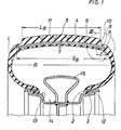
- the tire body consists essentially of rubber or rubber-like plastics, and it has a so-called radial car seat 1, in which the strength members are arranged in radial planes for tire in a known manner.
- the edges of the carcass 1 are anchored in the tire beads 2 by wrapping around the bead cores 3.
- a belt 6 which is tensile in the circumferential direction of the tire and consists of three superimposed cord plies 7, the reinforcements of which run parallel to each other in each position, but the reinforcements of which include angles which deviate with respect to the adjacent position with the circumferential direction of the tires. It is understood that all parts of the tire are vulcanized to each other.
- a widening section 8 on both sides of the tire body in the shoulder area is characteristic of the aforementioned tire.
- This widening section 8 has an essentially cylindrical, set-back base 9 running approximately parallel to the tread 4 and an approximately vertical step surface 10 which forms the edge of the tread 4 and thus determines its width LB.
- the belt 6 is essentially cylindrical or slightly concave, as is approximately the base 9, which in turn is on a diameter which is smaller than the diameter of the tread pattern on the base of its profile cuts at 11, in such a way that When the tread pattern is worn, the base area 9 does not come into contact with the road under normal driving conditions.
- the belt width is designated by G B and the largest width of the tire located at about half the height of the tire cross section is designated by B.
- the belt 6 extends laterally into each widening section 8 in that the belt part lying in the widening section 8 has a width which is approximately 25 to 40%, preferably 30% of the width by which the tire is at its widest point over the end of the Tread 4 protrudes so that the following inequality applies:
- zone Z in which the belt edge is at an angle to Carcass 1 runs is comparatively small and is preferably at most twice the dimension by which the belt edge projects from the vertical step surface 10.
- a correspondingly small support rubber in the form of the usual rubber strips is therefore sufficient.
- this bulge of the tire sidewall is also present in the lower (radially inner) half of the tire, so that the tire wall can spring when it is compressed and is not prevented by the bead pressure of a stiff and steep bead.
- the tire beads 2 are arranged on the radially outer circumference of a rigid, one-piece rim next to rim flanges 12 which extend radially outwards.
- the relatively flat bead cores 3 run with their base parallel to the rim seat surface, which can be horizontal or slightly inclined.
- Each tire bead 2 is secured axially on the inside by a so-called hump 13, next to which a deep bed 14 for the tire front is connected axially on the inside.
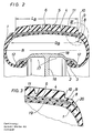
- a radial support part 15 which determines the largest rim diameter and which is used to support the tire in an emergency run.
- the carcass neutrals in the vehicle wheels of FIGS. 1 and 2 can be designed such that they obey the function of a chain line in the area of the rim flanges 12.
- a low-damping rubber layer 19 which is located between the two middle layers of a four-layer belt 6. It should not be thicker than 5 mm at most. It extends laterally up to approximately the height of the tread edge and is replaced there by an edge section 20 of a harder rubber mixture, which ends outside the widening section 8. Suitable hardnesses for the softer rubber layer 19 are in the range from 40 to 50 Shore A, while the edge sections 20 can have a hardness of 58 to 80 Shore A.
- vehicle wheels described are preferably intended for use in trucks, but that the invention is not limited to this application.
- the edge sections 20 preferably have a rebound resilience of approximately 40 to 50% (measured according to DIN 53512), while the rebound resilience of the rubber layer 19 should be 60 to 70%.
- the rebound elasticities of the rubber compounds enclosing the belt 6 should essentially correspond to the elasticity of the edge strips 20.
Landscapes
- Engineering & Computer Science (AREA)
- Mechanical Engineering (AREA)
- Tires In General (AREA)
Applications Claiming Priority (2)
| Application Number | Priority Date | Filing Date | Title |
|---|---|---|---|
| DE19843430500 DE3430500A1 (de) | 1984-08-18 | 1984-08-18 | Fahrzeugrad |
| DE3430500 | 1984-08-18 |
Publications (2)
| Publication Number | Publication Date |
|---|---|
| EP0173080A2 true EP0173080A2 (fr) | 1986-03-05 |
| EP0173080A3 EP0173080A3 (fr) | 1987-06-03 |
Family
ID=6243407
Family Applications (1)
| Application Number | Title | Priority Date | Filing Date |
|---|---|---|---|
| EP85109359A Ceased EP0173080A3 (fr) | 1984-08-18 | 1985-07-25 | Roue de véhicule |
Country Status (7)
| Country | Link |
|---|---|
| US (1) | US4741373A (fr) |
| EP (1) | EP0173080A3 (fr) |
| JP (1) | JPS6157402A (fr) |
| CA (1) | CA1251121A (fr) |
| DE (1) | DE3430500A1 (fr) |
| ES (1) | ES288682Y (fr) |
| GR (1) | GR851907B (fr) |
Cited By (3)
| Publication number | Priority date | Publication date | Assignee | Title |
|---|---|---|---|---|
| EP0779163A1 (fr) * | 1995-12-12 | 1997-06-18 | Sumitomo Rubber Industries Limited | Bandage pneumatique pour moto |
| US5783004A (en) * | 1996-12-04 | 1998-07-21 | Sumitomo Rubber Industries, Ltd. | Motorcycle tire with three belt plies |
| BE1024398B1 (nl) * | 2016-07-13 | 2018-02-13 | Mol Cy Nv | Luchtband voor rail-wegvoertuigen |
Families Citing this family (2)
| Publication number | Priority date | Publication date | Assignee | Title |
|---|---|---|---|---|
| BR0100126A (pt) * | 2000-02-01 | 2001-08-28 | Goodyear Tire & Rubber | Pneu radial com linha de lona aperfeiçoada |
| CN103370211B (zh) * | 2011-02-14 | 2017-09-01 | 株式会社普利司通 | 充气轮胎 |
Family Cites Families (10)
| Publication number | Priority date | Publication date | Assignee | Title |
|---|---|---|---|---|
| DE2355490A1 (de) * | 1973-11-07 | 1975-05-22 | Continental Gummi Werke Ag | Fahrzeugrad mit luftreifen |
| US3976115A (en) * | 1974-07-18 | 1976-08-24 | Uniroyal, S.A. | Pneumatic tire |
| FR2280519B1 (fr) * | 1974-07-31 | 1977-01-07 | Michelin & Cie | Perfectionnements aux enveloppes de pneumatiques |
| GB2030086A (en) * | 1978-09-16 | 1980-04-02 | Dunlop Ltd | Improvements in or relating to a pneumatic tyre and wheel rim assembly |
| GB2030087B (en) * | 1978-09-16 | 1984-09-05 | Dunlop Ltd | Pneumatic tyre and wheel rim assembly |
| DE3019742C2 (de) * | 1980-05-23 | 1989-03-16 | Continental Gummi-Werke Ag, 3000 Hannover | Fahrzeugrad |
| DE3105209A1 (de) * | 1981-02-13 | 1982-09-09 | Continental Gummi-Werke Ag, 3000 Hannover | Fahrzeugluftreifen |
| DE8103927U1 (de) * | 1981-02-13 | 1981-09-17 | Ninkaplast Gmbh, 4902 Bad Salzuflen | Halter fuer schriftstuecke |
| DE3132310A1 (de) * | 1981-08-17 | 1983-03-03 | Bayer Ag, 5090 Leverkusen | Luftreifen fuer schwere belastung |
| DE3237544A1 (de) * | 1982-10-09 | 1984-04-12 | Continental Gummi-Werke Ag, 3000 Hannover | Abdeckring fuer ein fahrzeugrad |
-
1984
- 1984-08-18 DE DE19843430500 patent/DE3430500A1/de not_active Withdrawn
-
1985
- 1985-07-05 GR GR851907A patent/GR851907B/el unknown
- 1985-07-25 EP EP85109359A patent/EP0173080A3/fr not_active Ceased
- 1985-08-14 ES ES1985288682U patent/ES288682Y/es not_active Expired
- 1985-08-15 CA CA000488786A patent/CA1251121A/fr not_active Expired
- 1985-08-16 JP JP60179536A patent/JPS6157402A/ja active Pending
-
1987
- 1987-03-05 US US07/023,921 patent/US4741373A/en not_active Expired - Fee Related
Cited By (3)
| Publication number | Priority date | Publication date | Assignee | Title |
|---|---|---|---|---|
| EP0779163A1 (fr) * | 1995-12-12 | 1997-06-18 | Sumitomo Rubber Industries Limited | Bandage pneumatique pour moto |
| US5783004A (en) * | 1996-12-04 | 1998-07-21 | Sumitomo Rubber Industries, Ltd. | Motorcycle tire with three belt plies |
| BE1024398B1 (nl) * | 2016-07-13 | 2018-02-13 | Mol Cy Nv | Luchtband voor rail-wegvoertuigen |
Also Published As
| Publication number | Publication date |
|---|---|
| CA1251121A (fr) | 1989-03-14 |
| JPS6157402A (ja) | 1986-03-24 |
| US4741373A (en) | 1988-05-03 |
| ES288682U (es) | 1986-01-01 |
| GR851907B (fr) | 1985-11-26 |
| ES288682Y (es) | 1986-09-01 |
| EP0173080A3 (fr) | 1987-06-03 |
| DE3430500A1 (de) | 1986-02-27 |
Similar Documents
| Publication | Publication Date | Title |
|---|---|---|
| DE69205610T2 (de) | Sicherheitsluftreifen. | |
| DE69005784T2 (de) | Radialer Luftreifen. | |
| DE69016359T2 (de) | Asymmetrischer Reifen. | |
| DE69613132T2 (de) | Lkw-reifen mit niedrigem höhen-/breitenverhältnis | |
| DE69722109T2 (de) | Reifen mit einer Lauffläche aus zwei verschiedenen Gummizusammensetzungen zur Steuerung der Abnutzung | |
| DE3783802T2 (de) | Lauffläche von Luftreifen. | |
| DE69905160T2 (de) | Verfahren zur herstellung eines fahrzeugreifens, ein damit hergestellter reifen und einen solchen reifen enthaltendes fahrzeugrad | |
| DE3780786T2 (de) | Radialreifen sowie felgen- und radialreifeneinheit. | |
| DE8032334U1 (de) | Reifen/felgenanordnung | |
| CH623781A5 (fr) | ||
| DE2724996A1 (de) | Luftreifen-felgen-anordnung | |
| DE2653658A1 (de) | Fahrzeugluftreifen mit plattfahreigenschaften | |
| DE2941852A1 (de) | Luftreifen in radialbauweise fuer schwerfahrzeuge | |
| DE60213204T2 (de) | Reifen für fahrzeugräder mit selbstragender funktion, und felge dafür | |
| DE3242865A1 (de) | Stuetzvorrichtung zur verhinderung der abplattung von luftreifen | |
| EP0079454B1 (fr) | Roue de véhicule | |
| DE69805101T2 (de) | Pkw-radialreifen mit verbesserter profilstruktur und entkuppelnden rillen | |
| DE3102614A1 (de) | Radialreifen-karkasse und verfahren zu ihrer herstellung | |
| DE68906125T2 (de) | Luftreifen fuer motorraeder. | |
| DE3321978C2 (fr) | ||
| DE2720265A1 (de) | Fahrzeug-sicherheitsreifen | |
| DE69306166T2 (de) | Verbesserungen an Reifen-Verstärkungsstrukturen für Fahrzeugräder | |
| DE60125667T2 (de) | LKW-Reifen | |
| EP0173080A2 (fr) | Roue de véhicule | |
| EP0328873B1 (fr) | Bandage pneumatique pour véhicules |
Legal Events
| Date | Code | Title | Description |
|---|---|---|---|
| PUAI | Public reference made under article 153(3) epc to a published international application that has entered the european phase |
Free format text: ORIGINAL CODE: 0009012 |
|
| AK | Designated contracting states |
Kind code of ref document: A2 Designated state(s): AT BE CH DE FR GB IT LI LU NL SE |
|
| PUAL | Search report despatched |
Free format text: ORIGINAL CODE: 0009013 |
|
| AK | Designated contracting states |
Kind code of ref document: A3 Designated state(s): AT BE CH DE FR GB IT LI LU NL SE |
|
| 17P | Request for examination filed |
Effective date: 19870416 |
|
| STAA | Information on the status of an ep patent application or granted ep patent |
Free format text: STATUS: EXAMINATION IS IN PROGRESS |
|
| 17Q | First examination report despatched |
Effective date: 19871130 |
|
| 18R | Application refused |
Effective date: 19880904 |
|
| APAF | Appeal reference modified |
Free format text: ORIGINAL CODE: EPIDOSCREFNE |
|
| RIN1 | Information on inventor provided before grant (corrected) |
Inventor name: MAUK, GERHARD, DIPL.-ING. |