EP0173359A2 - Dispositif d'accrochage pour structures suspendues - Google Patents
Dispositif d'accrochage pour structures suspendues Download PDFInfo
- Publication number
- EP0173359A2 EP0173359A2 EP85200973A EP85200973A EP0173359A2 EP 0173359 A2 EP0173359 A2 EP 0173359A2 EP 85200973 A EP85200973 A EP 85200973A EP 85200973 A EP85200973 A EP 85200973A EP 0173359 A2 EP0173359 A2 EP 0173359A2
- Authority
- EP
- European Patent Office
- Prior art keywords
- connecting piece
- attachment device
- attachment
- span
- forks
- Prior art date
- Legal status (The legal status is an assumption and is not a legal conclusion. Google has not performed a legal analysis and makes no representation as to the accuracy of the status listed.)
- Granted
Links
Images


Classifications
-
- E—FIXED CONSTRUCTIONS
- E04—BUILDING
- E04B—GENERAL BUILDING CONSTRUCTIONS; WALLS, e.g. PARTITIONS; ROOFS; FLOORS; CEILINGS; INSULATION OR OTHER PROTECTION OF BUILDINGS
- E04B9/00—Ceilings; Construction of ceilings, e.g. false ceilings; Ceiling construction with regard to insulation
- E04B9/18—Means for suspending the supporting construction
-
- E—FIXED CONSTRUCTIONS
- E04—BUILDING
- E04B—GENERAL BUILDING CONSTRUCTIONS; WALLS, e.g. PARTITIONS; ROOFS; FLOORS; CEILINGS; INSULATION OR OTHER PROTECTION OF BUILDINGS
- E04B9/00—Ceilings; Construction of ceilings, e.g. false ceilings; Ceiling construction with regard to insulation
- E04B9/06—Ceilings; Construction of ceilings, e.g. false ceilings; Ceiling construction with regard to insulation characterised by constructional features of the supporting construction, e.g. cross section or material of framework members
- E04B9/12—Connections between non-parallel members of the supporting construction
- E04B9/14—Connections between non-parallel members of the supporting construction all the members being discontinuous and laying at least partly in the same plane
Definitions
- This invention relates to a fastening device for suspended structures, namely an assembly of connection and fixing elements for mounting the beams of suspended structures and similar devices, under a bearing ceiling.
- Hanging systems were already being used for suspended structures which consist mainly of placing certain beams, in a given direction and at a relatively short distance from each other, so that cable trays and similar devices can be fixed between these beams placed at a relatively small distance from each other, while the transverse beams are simply placed between said longitudinal beams.
- the longitudinal beams form an obstacle to the free passage of the formed channel by the transverse beams.
- the object of the invention is therefore a fastening device which systematically eliminates the drawback described, as well as others, specific to these known devices.
- the attachment device consists, according to the invention, of the combination of a connecting piece and two already known forks to which the side members are connected, the whole forming a suspended grid crossed by continuous channels according to perpendicular directions.
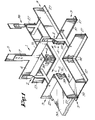
- Fig.l shows that the attachment device consists mainly of the combination of a connecting piece 1, two forks 2, to which are fixed the frames constituting the grid, each frame consisting of four rails 3 and as many d '' assembly brackets 4.
- the whole is attached to a suspensor, itself fixed to the supporting structure.
- Fig.l clearly shows that by using this hooking device, there are continuous channels both in the longitudinal direction L and in the transverse direction, allowing to place technical conduits.
- the connecting piece 1 has a horizontal span 6 surmounted in its middle by a vertical bar 7 used for attachment.
- This attachment bar 7 has the shape of a U-shaped profile, each wing 8 of which has a series of perforations 9 arranged vertically.
- the perforations in the wings 8 are located in facing the others, so as to be able to pass through these perforations and in cooperation with the perforations 10 of a vernier suspensor 11, two pins 12.
- the distances between the perforations 9 are slightly smaller than those between the perforations 10 of the suspension-vernier 11.
- the span 6 mainly consists of a vertical plate 13 in the same plane as the core 14 of the U of the hanging bar 7.
- the upper edge 15 of the vertical plate 13 is folded twice at an angle of 90 degrees.
- the front face 16 of the folded part and the vertical plate 13 have, on their vertical edges 17 and 18, series of perforations 19 and 20, arranged in such a way that the forks 2 can be fixed there by means of the pins 21.
- the connecting piece 1 is made sufficiently rigid by virtue of the U-shape of the fastening bar 7 and by virtue of the fact that the upper edge 15 of the span 6 is folded.
- the part is also reinforced by the lower edge 22 folded at 90 degrees and by the stamping 23 in the transition part 24 between the fastening bar 7 and the span 6.
- Fork 2 which has already been described in detail in another patent application by the same applicant, forms the link between the part connecting 1 and the side members 3; it is mainly used to fix the side rails in parallel and to support the technical pipes.
- the legs of the fork 2 have a projection 25 passing through a slot 26 in the spar 3.
- Each projection 25 has two lips 28, curved and forming a spring, hooking behind the core 27 of a spar 3.
- the transverse beams 3A are fixed at their ends to the longitudinal beams 3B by means of the assembly brackets 4.
- Each assembly square 4 consists of a blade folded into a square, provided with barbs 29 and bores 30.
- Passers-by 31 at the ends of the beams allow the transverse beams 3A to be attached to the longitudinal beams 3B using the assembly brackets 4.
- the bores 30 in the assembly brackets 4 correspond to the bores 32 in the longitudinal members, which makes it possible to use an additional fixing means, for example a rivet 33 (fig. 6).
- All elements of the construction will preferably be made of galvanized steel.
- the assembly brackets 4 are mounted on all the transverse beams 3A and these are fixed to the longitudinal beams 3A using these brackets.
- the panels 34 and the sealing strip 35 can be placed.
- the sealing strip 35 is fixed by means of beads 36 forming a spring (fig. 7) between the wings 37 of the side members 3.
- One of the possible variants is a hooking device where the connecting piece 1, the forks 2 in the form of a jumper and / or the mounting brackets 4 form a whole, so that the mounting of the suspended structure is faster.
Landscapes
- Engineering & Computer Science (AREA)
- Architecture (AREA)
- Physics & Mathematics (AREA)
- Electromagnetism (AREA)
- Civil Engineering (AREA)
- Structural Engineering (AREA)
- Prostheses (AREA)
- Mutual Connection Of Rods And Tubes (AREA)
Abstract
Description
- Cette invention concerne un dispositif d'accrochage pour des structures suspendues, à savoir un assemblage d'éléments de connexion et de fixation pour monter les longerons de structures suspendues et de dispositifs semblables, sous un plafond portant.
- On cannait déjà des systèmes d'accrochage pour des structures suspendues qui consistent principalement dans le placement de certains longerons, dans un sens donné et à une distance relativement faible les uns des autres, de façon à pouvoir fixer les chemins de câbles et dispositifs semblables entre ces longerons placés à une distance relativement faible les uns des autres, tandis que les longerons transversaux sont simplement placés entre les dits longerons longitudinaux. Lorsque, avec les dispositifs cités, on désire monter des chemins de câbles et des dispositifs semblables, à la fois dans les sens longitudinal et transversal, on rencontre l'inconvénient que les longerons longitudinaux forment un obstacle au libre passage du canal formé par les longerons transversaux.
- Les termes "longitudinal" et "transversal", déjà mentionnés et qui le seront encore plus loin dans la description, ne sont employés que pour faire la distinction entre les deux directions perpendiculaires des longerons.
- L'objet de l'invention est donc un dispositif d'accrochage qui élimine systématiquement l'inconvénient décrit, ainsi que d'autres, propres à ces dispositifs connus.
- A cet effet, le dispositif d'accrochage se compose, selon l'invention, de la conbinaison d'une pièce de liaison et de deux fourches déjà connues auxquelles sont reliés les longerons, le tout formant une grille suspendue traversée de canaux continus suivant des directions perpendiculaires.
- Dans le but de mieux démontrer les caractéristiques de l'invention suit, à titre d'exemple et sans aucun caractère limitatif, une description d'une réalisation préférable avec référence aux dessins annexés dans lesquels :
- figure 1 est un croquis représentant en perspective le principe du dispositif d'accrochage;
- figure 2 est une vue semblable à la fig.l, mais représentant, en l'occurence, une réalisation possible;
- figure 3 est une vue de face de la pièce de liaison faisant partie du dispositif d'accrochage;
- figure 4 est une vue de côté de la fig.3;
- figure 5 est une vue par le dessus de la fig.3;
- figure 6 est une coupe selon la ligne VI-VI de la fig.2;
- figure 7 est une coupe selon la ligne VII-VII de la fig.2;
- La fig.l montre que le dispositif d'accrochage se compose principalement de la combinaison d'une pièce de liaison 1, de deux fourches 2, auxquelles sont fixés les cadres constituant la grille, chaque cadre se composant de quatre longerons 3 et autant d'équerres d'assemblage 4.
- L'ensemble est attaché à un suspensoir, lui-même fixé à la construction portante.
- La fig.l montre clairement qu'en employant ce dispositif d'accrochage, il subsiste des canaux continus tant dans le sens longitudinal L que dans le sens transversal D, permettant d'y placer des conduites techniques.
- La pièce de liaison 1 a une travée horizontale 6 surmontée en son milieu d'une barre verticale 7 servant à l'accrochage. Cette barre d'accrochage 7 a la forme d'un profilé en U, dont chaque aile 8 comporte une série de perforations 9 disposées verticalement. Les perforations dans les ailes 8 se trouvent les unes en face des autres, de façon à pouvoir passer, par ces perforations et en coopération avec les perforations 10 d'un suspensoir-vernier 11, deux broches 12. Il faut, pour pouvoir effectivement employer le suspensoir-vernier, que les distances entre les perforations 9 soient légèrement plus petites que celles entre les perforations 10 du suspensoir-vernier 11.
- La travée 6 se compose principalement d'une plaque verticale 13 dans le même plan que l'âme 14 de l'U de la barre d'accrochage 7. Le bord supérieur 15 de la plaque verticale 13 est replié deux fois selon un angle de 90 degrés.
- La face avant 16 de la partie pliée et la plaque verticale 13 présentent, sur leurs bords verticaux 17 et 18, des séries de perforations 19 et 20, disposées de telle façon que les fourches 2 peuvent y être fixées au moyen des broches 21.
- La pièce de liaison 1 est rendue suffisamment rigide grâce à la forme en U de la barre d'accrochage 7 et grâce au fait que le bord supérieur 15 de la travée 6 est replié. La pièce est également renforcée par le bord inférieur 22 replié à 90 degrés et par l'emboutissage 23 dans la partie de transition 24 entre la barre d'accrochage 7 et la travée 6.
- La fourche 2, qui a déjà été décrite en détail dans une autre demande de brevet du même demandeur, forme le lien entre la pièce de liaison 1 et les longerons 3; elle sert surtout à fixer les longerons en parallèle et à suporter les conduites techniques.
- Les pattes de la fourche 2 présentent une saillie 25 traversant une fente 26 du longeron 3. Chaque saillie 25 a deux lèvres 28, recourbées et formant ressort, s'accrochant derrière l'âme 27 d'un longeron 3.
- Les longerons transversaux 3A sont fixés à leurs extrémités aux longerons longitudinaux 3B au moyen des équerres d'assemblage 4.
- Chaque équerre d'assemblage 4 se compose d'une lame pliée en équerre, pourvue d'ardillons 29 et d'alésages 30.
- Des passants 31 aux extrémités des longerons permettent d'attacher les longerons transversaux 3A aux longerons longitudinaux 3B à l'aide des équerres d'assemblages 4.
- Les alésages 30 dans les équerres d'assemblage 4 correspondent aux alésages 32 dans les longerons, ce qui permet d'employer un moyen de fixation supplémentaire, par exemple un rivet 33 (fig.6).
- Tous les éléments de la construction seront réalisés de préférence en acier galvanisé.
- Un procédé de montage, habituel mais non exclusif, est décrit ci-après.
- On fixe deux fourches 2 à la pièce de liaison 1. Cet ensemble de trois pièces est ensuite accroché au suspensoir-vernier 11, préalablement attaché à la construction portante. Lorsque plusieurs de ces ensembles sont attachés à la construction portante, les longerons longitudinaux 3B sont montés sur les dents des fourches 2.
- On monte les équerres d'assemblage 4 sur tous les longerons transversaux 3A et on fixe ceux-ci aux longerons longitudinaux 3A à l'aide de ces équerres.
- Lorsque les conduites techniques et éventuellement d'autres accessoires sont installés, on peut placer les panneaux 34 et la bande d'obturation 35. La bande d'obturation 35 se fixe au moyen de bourrelets 36 formant ressort (fig.7) entre les ailes 37 des longerons 3.
- La construction décrite suffit normalement à suspendre les panneaux 34, la bande d'obturation 35 et divers accessoires techniques. Cela n'empêche pas de prévoir des points de suspension 38 (fig.l) supplémentaires, qui ne se composent que d'une seule fourche.
- L'invention ne se limite pas à la réalisation décrite à titre d'exemple et représentée aux dessins annexés; ce dispositif de suspension ainsi que ses parties constitutives peuvent présenter toutes sortes de formes et de dimensions sans sortir du cadre de l'invention.
- Il est évident que les liaisons entre les différentes parties peuvent être réalisées autrement que comme décrit précédemment.
- Une des variantes possibles est un dispositif d'accrochage où la pièce de liaison 1, les fourches 2 en forme de cavalier et/ou les équerres de montage 4 forment un tout, afin que le montage de la structure suspendue soit plus rapide.
Claims (12)
Applications Claiming Priority (2)
| Application Number | Priority Date | Filing Date | Title |
|---|---|---|---|
| BE2/60485A BE900450A (nl) | 1984-08-29 | 1984-08-29 | Ophanginrichting voor plafondstrukturen. |
| BE260485 | 1984-08-29 |
Publications (3)
| Publication Number | Publication Date |
|---|---|
| EP0173359A2 true EP0173359A2 (fr) | 1986-03-05 |
| EP0173359A3 EP0173359A3 (en) | 1987-08-26 |
| EP0173359B1 EP0173359B1 (fr) | 1989-10-18 |
Family
ID=3865704
Family Applications (1)
| Application Number | Title | Priority Date | Filing Date |
|---|---|---|---|
| EP19850200973 Expired EP0173359B1 (fr) | 1984-08-29 | 1985-06-19 | Dispositif d'accrochage pour structures suspendues |
Country Status (1)
| Country | Link |
|---|---|
| EP (1) | EP0173359B1 (fr) |
Cited By (1)
| Publication number | Priority date | Publication date | Assignee | Title |
|---|---|---|---|---|
| WO2013184372A1 (fr) * | 2012-06-05 | 2013-12-12 | Usg Interiors, Llc | Chape modulaire à deux parties |
Family Cites Families (3)
| Publication number | Priority date | Publication date | Assignee | Title |
|---|---|---|---|---|
| US3590546A (en) * | 1969-04-21 | 1971-07-06 | Air Factors | Suspended ceiling support and air distribution outlet assembly |
| US4068444A (en) * | 1977-05-02 | 1978-01-17 | Armstrong Cork Company | Ceiling runner with closure strip |
| NL8002018A (nl) * | 1980-04-03 | 1981-11-02 | Nemaco Trading Ltd | Plafond. |
-
1985
- 1985-06-19 EP EP19850200973 patent/EP0173359B1/fr not_active Expired
Cited By (2)
| Publication number | Priority date | Publication date | Assignee | Title |
|---|---|---|---|---|
| WO2013184372A1 (fr) * | 2012-06-05 | 2013-12-12 | Usg Interiors, Llc | Chape modulaire à deux parties |
| US8615947B2 (en) | 2012-06-05 | 2013-12-31 | Usg Interiors, Llc | Two-piece modular yoke |
Also Published As
| Publication number | Publication date |
|---|---|
| EP0173359B1 (fr) | 1989-10-18 |
| EP0173359A3 (en) | 1987-08-26 |
Similar Documents
| Publication | Publication Date | Title |
|---|---|---|
| EP0010042B1 (fr) | Ossature de paroi avec ouverture et porte pour box préfabriqué pour cheval | |
| FR2458640A1 (fr) | Faux-plafond metallique | |
| FR2502671A1 (fr) | Dispositif de liaison pour planches d'echafaudages | |
| EP0173359A2 (fr) | Dispositif d'accrochage pour structures suspendues | |
| EP0004504B1 (fr) | Clôture réalisée au moyen de poteaux en profilé de section polygonale | |
| FR2762630A1 (fr) | Grille pour la construction d'un faux plafond suspendu | |
| FR2652113A1 (fr) | Structure modulable pour abri et similaires. avec systeme recuperateur d'eau de condensation et toit escamotable. | |
| FR2590303A1 (fr) | Perfectionnements aux plafonds a ecrans | |
| EP0575269A1 (fr) | Dispositif pour suspendre les chemins de câbles | |
| FR2898374A1 (fr) | Module de plancher et plancher forme a partir de tels modules | |
| FR2711695A1 (fr) | Suspente pour profilé de grande portée, notamment pour la réalisation de faux-plafonds. | |
| FR2740800A1 (fr) | Dispositif de fixation d'un faux plafond dans un couloir | |
| FR2636292A3 (fr) | Dispositif pour presenter des vehicules a deux roues | |
| FR2664633A1 (fr) | Plafond suspendu. | |
| EP0908580B1 (fr) | Dispositif pour la construction d'une façade de plaques | |
| FR2737521A1 (fr) | Dispositif de protection pour passerelles de support de panneaux de coffrage | |
| FR2516142A1 (fr) | Renvoi d'angle pour echafaudage | |
| EP0137086B1 (fr) | Dispositif de montage d'un faux plafond constitué d'une nappe tendue horizontalement | |
| EP0903503B1 (fr) | Système de fixation d'éléments de construction secondaires sur des plats à boudin utilisés dans la construction marine | |
| EP2460952A1 (fr) | Clôture comprenant au moins un poteau et au moins un panneau nervuré | |
| FR2504176A1 (fr) | Dispositif pour raccorder des tubes d'echafaudage a des profiles speciaux de poutre | |
| FR2522486A1 (fr) | Installation combinee de sieges et de couchettes pour abris contre les catastrophes | |
| FR2637635A1 (fr) | Rambarde perfectionnee et dispositif permettant sa fixation au sol | |
| FR2683569A1 (fr) | Procede et dispositif d'assemblage de poutres en bois. | |
| FR2670525A1 (fr) | Dispositif de fixation pour planchers d'echafaudages. |
Legal Events
| Date | Code | Title | Description |
|---|---|---|---|
| PUAI | Public reference made under article 153(3) epc to a published international application that has entered the european phase |
Free format text: ORIGINAL CODE: 0009012 |
|
| AK | Designated contracting states |
Kind code of ref document: A2 Designated state(s): DE FR GB |
|
| DET | De: translation of patent claims | ||
| PUAL | Search report despatched |
Free format text: ORIGINAL CODE: 0009013 |
|
| AK | Designated contracting states |
Kind code of ref document: A3 Designated state(s): DE FR GB |
|
| 17P | Request for examination filed |
Effective date: 19871023 |
|
| 17Q | First examination report despatched |
Effective date: 19880706 |
|
| GRAA | (expected) grant |
Free format text: ORIGINAL CODE: 0009210 |
|
| AK | Designated contracting states |
Kind code of ref document: B1 Designated state(s): DE FR GB |
|
| GBT | Gb: translation of ep patent filed (gb section 77(6)(a)/1977) | ||
| REF | Corresponds to: |
Ref document number: 3573818 Country of ref document: DE Date of ref document: 19891123 |
|
| PLBE | No opposition filed within time limit |
Free format text: ORIGINAL CODE: 0009261 |
|
| STAA | Information on the status of an ep patent application or granted ep patent |
Free format text: STATUS: NO OPPOSITION FILED WITHIN TIME LIMIT |
|
| 26N | No opposition filed | ||
| PGFP | Annual fee paid to national office [announced via postgrant information from national office to epo] |
Ref country code: FR Payment date: 19960524 Year of fee payment: 12 |
|
| PGFP | Annual fee paid to national office [announced via postgrant information from national office to epo] |
Ref country code: GB Payment date: 19960618 Year of fee payment: 12 |
|
| PGFP | Annual fee paid to national office [announced via postgrant information from national office to epo] |
Ref country code: DE Payment date: 19960711 Year of fee payment: 12 |
|
| PG25 | Lapsed in a contracting state [announced via postgrant information from national office to epo] |
Ref country code: GB Free format text: LAPSE BECAUSE OF NON-PAYMENT OF DUE FEES Effective date: 19970619 |
|
| GBPC | Gb: european patent ceased through non-payment of renewal fee |
Effective date: 19970619 |
|
| PG25 | Lapsed in a contracting state [announced via postgrant information from national office to epo] |
Ref country code: FR Free format text: LAPSE BECAUSE OF NON-PAYMENT OF DUE FEES Effective date: 19980227 |
|
| PG25 | Lapsed in a contracting state [announced via postgrant information from national office to epo] |
Ref country code: DE Free format text: LAPSE BECAUSE OF NON-PAYMENT OF DUE FEES Effective date: 19980303 |
|
| REG | Reference to a national code |
Ref country code: FR Ref legal event code: ST |
|
| REG | Reference to a national code |
Ref country code: FR Ref legal event code: ST |