EP0173432B1 - Rouleau humidificateur pour machine de filature, retordage ou bobinage - Google Patents
Rouleau humidificateur pour machine de filature, retordage ou bobinage Download PDFInfo
- Publication number
- EP0173432B1 EP0173432B1 EP19850304722 EP85304722A EP0173432B1 EP 0173432 B1 EP0173432 B1 EP 0173432B1 EP 19850304722 EP19850304722 EP 19850304722 EP 85304722 A EP85304722 A EP 85304722A EP 0173432 B1 EP0173432 B1 EP 0173432B1
- Authority
- EP
- European Patent Office
- Prior art keywords
- roller
- yarn
- liquid
- frame according
- shaft
- Prior art date
- Legal status (The legal status is an assumption and is not a legal conclusion. Google has not performed a legal analysis and makes no representation as to the accuracy of the status listed.)
- Expired
Links
- 238000009987 spinning Methods 0.000 title claims description 7
- 238000004804 winding Methods 0.000 title claims description 5
- 239000007788 liquid Substances 0.000 claims description 20
- 230000002745 absorbent Effects 0.000 claims description 5
- 239000002250 absorbent Substances 0.000 claims description 5
- 239000000463 material Substances 0.000 claims description 4
- 239000004753 textile Substances 0.000 claims description 2
- XLYOFNOQVPJJNP-UHFFFAOYSA-N water Substances O XLYOFNOQVPJJNP-UHFFFAOYSA-N 0.000 description 19
- 238000010276 construction Methods 0.000 description 6
- 238000007378 ring spinning Methods 0.000 description 3
- 206010020112 Hirsutism Diseases 0.000 description 2
- 241000208202 Linaceae Species 0.000 description 2
- 235000004431 Linum usitatissimum Nutrition 0.000 description 2
- 230000000694 effects Effects 0.000 description 2
- 230000005484 gravity Effects 0.000 description 2
- 238000009499 grossing Methods 0.000 description 2
- 229920006395 saturated elastomer Polymers 0.000 description 2
- 239000000654 additive Substances 0.000 description 1
- 230000000996 additive effect Effects 0.000 description 1
- 230000003190 augmentative effect Effects 0.000 description 1
- 239000000428 dust Substances 0.000 description 1
- 238000011835 investigation Methods 0.000 description 1
- 239000000314 lubricant Substances 0.000 description 1
- 230000014759 maintenance of location Effects 0.000 description 1
- 239000000203 mixture Substances 0.000 description 1
- 239000011148 porous material Substances 0.000 description 1
- 238000009941 weaving Methods 0.000 description 1
Images

Classifications
-
- D—TEXTILES; PAPER
- D01—NATURAL OR MAN-MADE THREADS OR FIBRES; SPINNING
- D01H—SPINNING OR TWISTING
- D01H13/00—Other common constructional features, details or accessories
- D01H13/30—Moistening, sizing, oiling, waxing, colouring, or drying yarns or the like as incidental measures during spinning or twisting
- D01H13/306—Moistening, sizing, oiling, waxing, colouring, or drying yarns or the like as incidental measures during spinning or twisting by applying fluids, e.g. steam or oiling liquids
-
- B—PERFORMING OPERATIONS; TRANSPORTING
- B65—CONVEYING; PACKING; STORING; HANDLING THIN OR FILAMENTARY MATERIAL
- B65H—HANDLING THIN OR FILAMENTARY MATERIAL, e.g. SHEETS, WEBS, CABLES
- B65H71/00—Moistening, sizing, oiling, waxing, colouring or drying filamentary material as additional measures during package formation
-
- B—PERFORMING OPERATIONS; TRANSPORTING
- B65—CONVEYING; PACKING; STORING; HANDLING THIN OR FILAMENTARY MATERIAL
- B65H—HANDLING THIN OR FILAMENTARY MATERIAL, e.g. SHEETS, WEBS, CABLES
- B65H2701/00—Handled material; Storage means
- B65H2701/30—Handled filamentary material
- B65H2701/31—Textiles threads or artificial strands of filaments
Definitions
- the yarn may be caused to engage the surface of a dampening roller which helps to smooth the yarn and reduce its hairiness and which may also, if required, treat the yarn with a lubricant by means of liquid or an additive to the water so as, for example, to make it more receptive to weaving.
- the roller needs to be located in advance of the rotary mechanism, i.e. the spinning, twisting or winding mechanism.
- the roller may be located between the drawing rollers and a thread plate formed with an eye which guides the yarn to the traveller on the ring.
- dampening rollers are located at intervals on a common shaft which may extend for the whole length of the frame.
- the yarn normally makes only comparatively light contact with the front surface of the respective roller, i.e. over an arc of only a few degrees.
- the lower part of the roller is immersed in a trough extending along the frame either in a single length or a number of shorter lengths.
- the roller As the surface of the roller emerges from the liquid, e.g. water in the trough, it carries a relatively thick film of water which tends to be thrown outwardly by centrifugal force. Accordingly, in order to reduce the proportion of water thrown off by the roller before application to the yarn, the roller is driven in a direction such that the surface engaging the yarn moves upwardly so that engagement occurs approximately a quarter of a revolution after the surface of the roller has left the trough rather than after approximately three quarters of a revolution as would be the case for the opposite direction of rotation. Even with this arrangement, however, quite a lot of water is thrown off the roller and settles on surfaces at the front of the machine, thus causing loose fibres and dust to stick to these surfaces, leading to a dirty machine.
- the liquid e.g. water in the trough
- US-A-3137117 discloses moistening a yarn, during drawing and twisting, by contact with annular disc-like elements of which at least one is porous and is mounted on a hollow shaft. The axes of rotation of the discs are parallel to the direction of the yarn.
- a textile spinning, twisting or winding frame comprises a plurality of heads each including, in advance of the rotary mechanism, a dampening roller for engagement with the yarn to be treated and connected to a source of liquid which can pass to and through the structure of the roller to its yarn-engaging surface; each roller is mounted for rotation on a hollow shaft connected to a source of liquid and formed with at least one hole through its wall in register with the roller, for the passage of liquid through the structure of the roller to its yarn-engaging surface.
- a roller as used in the present invention has a core of absorbent material sandwiched between a pair of end collars, through which the liquid can percolate to the yarn-engaging surface.
- This core which may be, for example, of felt or flannel, is maintained in a saturated condition and can thus effectively dampen the yarn, but there is little or no excessive film of water on the surfaces, so that the quantity of water thrown off is very much reduced.
- the roller can be made in one piece with fine holes or pores extending to the yarn-engaging surface of the roller.
- An annular recess may be formed in the surface of the roller which engages the shaft and which forms a small reservoir within the body of the roller into which water may flow from the shaft and from which water may flow to the yarn-engaging surface.
- the water may pass to the roller by gravity as the shaft rotates or a pump may be provided to pressurise the water to force it through the holes.
- the surface of the roller moves in the same direction as the yarn, preferably at a greater speed. This is found to increase the smoothing effect of the roller, the reason for this apparently depending on the observed fact that the majority of fibres responsible for the hairiness of the yarn lie with their free ends pointing in the direction of travel. Consequently, the effect of the normal direction of rotation of the smoothing roller is to bend these fibres back against their natural attitude and at least a proportion of such fibres inevitably spring out again.
- the appropriate direction of rotation particularly when the surface speed of the roller is greater than that of the yarn, the attitude of the fibres is maintained and they are merely pressed into the body of the yarn without major risk of springing out again.
- sliver or rove 2 passes through a drawing head shown schematically as 4 and thence to drawing rollers 6, 6'. From the drawing rollers the fibres now in the form of yarn pass a suction device 18 which takes up the fibres in the event of an end break, and then passes through the eye of a thread plate 8 to a traveller 10 rotating on a ring 12 to be wound onto a package 14 on a rotary spindle 16.
- a dampening roller 20 is located between the drawing rollers 6, 6' and the thread guide plate 8 and, as shown by the arrow, rotates in an anticlockwise direction so that its surface moves in the same direction as the yarn.
- the roller 20 is mounted on a hollow tubular shaft 26 to the interior of which water is supplied and percolates outwardly to the surface of the roller where it is applied to the yarn.
- the surface speed of the roller is preferably faster than that of the yarn, and in a particular example, with a yarn speed of 20 metres per minute, the surface speed of the roller is 40 metres per minute.
- the frame as a whole is much dryer and hence cleaner, and the occasional drop of water which may fall, rather than be sprayed, from the roller 20 falls onto the top of the thread guide plate 8 and drains backwardly from there to be caught in a small drain trough 30 fitted to the reciprocating ring rail.
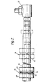
- roller 20 and the shaft 26 Details of the roller 20 and the shaft 26 are illustrated in Figure 2, water or other liquid being supplied to the roller 20 from a reservoir (not illustrated) via a rotating joint 27.
- a pump (not shown) may be included to boost the water pressure.
- the shaft 26 extends along the length of the frame and carries a roller 20 for each spinning head, two such rollers being shown by way of example. In the vicinity of each roller, two small diameter holes 32 are drilled through the wall of the shaft and the water or other liquid fills the shaft to almost half its depth. The liquid percolates downwardly by gravity through the holes 32 at a rate which depends on the head of liquid within the shaft 26, augmented if necessary by a pump.
- the roller 20 is constructed of three parts, i.e. an inner core 24 sandwiched between two outer collars 22 and 22'.
- the core 24 is of an absorbent material such as felt and the collars are shaped to form a channel for the yarn so that it engages the surface of the absorbent material of the core.
- the collars 22, 22' are locked to the shaft 26 by means of socket-headed screws (not shown) and as the shaft rotates the moisture escapes through the holes 32 in very small droplets onto the absorbent core 24, which is maintained in a saturated condition so as to dampen the yarn.
- the roller is made as a single piece formed with a recess 34 forming a small annular reservoir in communication with the holes 32. Further small holes 36 extend radially from this reservoir 34 to the yarn engaging surface of the roller 20 which is situated within a locating groove 38.
- Figure 3 leads to considerably improved results in comparison with the normal use of a water trough
- the construction of Figure 2 is preferred, since it leads to a more even distribution and retention of the water on the surface of the roller and hence more effective and cleaner operation.
Landscapes
- Engineering & Computer Science (AREA)
- Chemical & Material Sciences (AREA)
- Oil, Petroleum & Natural Gas (AREA)
- Mechanical Engineering (AREA)
- Textile Engineering (AREA)
- Spinning Or Twisting Of Yarns (AREA)
Claims (7)
Applications Claiming Priority (2)
| Application Number | Priority Date | Filing Date | Title |
|---|---|---|---|
| GB848417589A GB8417589D0 (en) | 1984-07-10 | 1984-07-10 | Spinning of flax |
| GB8417589 | 1984-07-10 |
Publications (3)
| Publication Number | Publication Date |
|---|---|
| EP0173432A2 EP0173432A2 (fr) | 1986-03-05 |
| EP0173432A3 EP0173432A3 (en) | 1987-08-19 |
| EP0173432B1 true EP0173432B1 (fr) | 1990-05-02 |
Family
ID=10563682
Family Applications (1)
| Application Number | Title | Priority Date | Filing Date |
|---|---|---|---|
| EP19850304722 Expired EP0173432B1 (fr) | 1984-07-10 | 1985-07-02 | Rouleau humidificateur pour machine de filature, retordage ou bobinage |
Country Status (2)
| Country | Link |
|---|---|
| EP (1) | EP0173432B1 (fr) |
| GB (1) | GB8417589D0 (fr) |
Families Citing this family (3)
| Publication number | Priority date | Publication date | Assignee | Title |
|---|---|---|---|---|
| DE19843132A1 (de) * | 1997-09-27 | 1999-04-08 | Barmag Barmer Maschf | Verfahren zum Auftragen einer Flüssigkeit auf einen laufenden Faden |
| CN103469405B (zh) * | 2013-09-04 | 2016-08-17 | 上海八达纺织印染服装有限公司 | 一种复合纺纱方法及其装置 |
| CN107142581A (zh) * | 2017-05-11 | 2017-09-08 | 武汉纺织大学 | 一种粘合纺纱方法及其粘合纺纱装置 |
Family Cites Families (8)
| Publication number | Priority date | Publication date | Assignee | Title |
|---|---|---|---|---|
| DE558283C (de) * | 1929-11-07 | 1932-09-05 | Aubrey Edgerton Meyer | Maschine zum Offendrehen von befeuchtetem, gedrehtem und mit Klebstoff versehenem Garn |
| DE646386C (de) * | 1935-02-06 | 1937-06-12 | Naamlooze Vennootschap Drya Mi | Dochtlose Benetzungsvorrichtung fuer Faeden an Zwirnmaschinen |
| US2320956A (en) * | 1942-05-26 | 1943-06-01 | John E Turcotte | Attachment for converting dry twisters into wet twisters |
| US2334420A (en) * | 1943-04-08 | 1943-11-16 | Homer V Lang | Means for processing yarn |
| US3182439A (en) * | 1961-11-29 | 1965-05-11 | Bruno Cecchi | Twisting and humidifying apparatus for textile rovings |
| US3137117A (en) * | 1962-01-22 | 1964-06-16 | Cecchi Bruno | Apparatus for moistening yarn while drawing and twisting |
| FR1439119A (fr) * | 1965-03-22 | 1966-05-20 | Anciens Etablissements M Mirai | Perfectionnements aux dispositifs pour l'imprégnation des fils textiles |
| DE3423942A1 (de) * | 1984-06-29 | 1986-01-09 | Institute für Textil- und Faserforschung Stuttgart, 7306 Denkendorf | Verfahren und einrichtung zum behandeln von faeden |
-
1984
- 1984-07-10 GB GB848417589A patent/GB8417589D0/en active Pending
-
1985
- 1985-07-02 EP EP19850304722 patent/EP0173432B1/fr not_active Expired
Also Published As
| Publication number | Publication date |
|---|---|
| EP0173432A3 (en) | 1987-08-19 |
| EP0173432A2 (fr) | 1986-03-05 |
| GB8417589D0 (en) | 1984-08-15 |
Similar Documents
| Publication | Publication Date | Title |
|---|---|---|
| JPS6120652B2 (fr) | ||
| US2718111A (en) | Yarn twister for spinning frames | |
| EP0173432A2 (fr) | Rouleau humidificateur pour machine de filature, retordage ou bobinage | |
| US3864901A (en) | Wetting mechanism for a textile yarn processing machine | |
| CN211497949U (zh) | 一种涡流纺纱线纺纱用预湿设备 | |
| JP2618481B2 (ja) | 織物糸の表面にパラフィン油を塗布する塗布装置 | |
| EP0947617B2 (fr) | Méthode pour fabriquer un fil et métier à filer pour cela | |
| US2334420A (en) | Means for processing yarn | |
| US1534071A (en) | Roller mechanism for spinning machines | |
| US4509230A (en) | Drafting mechanism for a spinning machine | |
| US2412641A (en) | Spinning of cotton yarn | |
| DE864654C (de) | Verfahren und Vorrichtung zum Befeuchten oder Besprengen laufender Bahnen | |
| US2089229A (en) | Operation and apparatus in which twist is imparted to threads | |
| US3458983A (en) | Process and apparatus for twisting threads | |
| US2671304A (en) | Spinning system | |
| JPS60167941A (ja) | リングレス精紡機におけるオイリング装置 | |
| US4208891A (en) | Application of liquid to yarns | |
| US1578242A (en) | Yarn-treating mechanism for winding machines | |
| US4601166A (en) | Spinning device | |
| EP0188220B1 (fr) | Appareil pour la production de fil à âme | |
| US2677949A (en) | Thread wiper-guide for use in thread-spinning apparatus | |
| KR0147001B1 (ko) | 용융방사형 스판덱스 섬유 제조장치 | |
| US2633607A (en) | Clip | |
| EP0907775B1 (fr) | Dispositif pour appliquer des liquides sur des fils | |
| US2362782A (en) | Clearer for roving or spinning frames |
Legal Events
| Date | Code | Title | Description |
|---|---|---|---|
| PUAI | Public reference made under article 153(3) epc to a published international application that has entered the european phase |
Free format text: ORIGINAL CODE: 0009012 |
|
| AK | Designated contracting states |
Kind code of ref document: A2 Designated state(s): BE FR GB IT |
|
| PUAL | Search report despatched |
Free format text: ORIGINAL CODE: 0009013 |
|
| AK | Designated contracting states |
Kind code of ref document: A3 Designated state(s): BE FR GB IT |
|
| 17P | Request for examination filed |
Effective date: 19880128 |
|
| 17Q | First examination report despatched |
Effective date: 19890210 |
|
| GRAA | (expected) grant |
Free format text: ORIGINAL CODE: 0009210 |
|
| AK | Designated contracting states |
Kind code of ref document: B1 Designated state(s): BE FR GB IT |
|
| ET | Fr: translation filed | ||
| ITF | It: translation for a ep patent filed | ||
| PGFP | Annual fee paid to national office [announced via postgrant information from national office to epo] |
Ref country code: BE Payment date: 19900808 Year of fee payment: 6 |
|
| PLBE | No opposition filed within time limit |
Free format text: ORIGINAL CODE: 0009261 |
|
| STAA | Information on the status of an ep patent application or granted ep patent |
Free format text: STATUS: NO OPPOSITION FILED WITHIN TIME LIMIT |
|
| 26N | No opposition filed | ||
| ITTA | It: last paid annual fee | ||
| PG25 | Lapsed in a contracting state [announced via postgrant information from national office to epo] |
Ref country code: BE Effective date: 19910731 |
|
| PGFP | Annual fee paid to national office [announced via postgrant information from national office to epo] |
Ref country code: GB Payment date: 19910814 Year of fee payment: 7 |
|
| PGFP | Annual fee paid to national office [announced via postgrant information from national office to epo] |
Ref country code: FR Payment date: 19910823 Year of fee payment: 7 |
|
| BERE | Be: lapsed |
Owner name: JAMES MACKIE & SONS LTD Effective date: 19910731 |
|
| PG25 | Lapsed in a contracting state [announced via postgrant information from national office to epo] |
Ref country code: GB Effective date: 19920702 |
|
| GBPC | Gb: european patent ceased through non-payment of renewal fee |
Effective date: 19920702 |
|
| PG25 | Lapsed in a contracting state [announced via postgrant information from national office to epo] |
Ref country code: FR Effective date: 19930331 |
|
| REG | Reference to a national code |
Ref country code: FR Ref legal event code: ST |