EP0173665A1 - Anchoring means for a rod in a terminal holder - Google Patents
Anchoring means for a rod in a terminal holder Download PDFInfo
- Publication number
- EP0173665A1 EP0173665A1 EP85850269A EP85850269A EP0173665A1 EP 0173665 A1 EP0173665 A1 EP 0173665A1 EP 85850269 A EP85850269 A EP 85850269A EP 85850269 A EP85850269 A EP 85850269A EP 0173665 A1 EP0173665 A1 EP 0173665A1
- Authority
- EP
- European Patent Office
- Prior art keywords
- rod
- sleeve
- sleeve body
- anchoring means
- widened
- Prior art date
- Legal status (The legal status is an assumption and is not a legal conclusion. Google has not performed a legal analysis and makes no representation as to the accuracy of the status listed.)
- Ceased
Links
Images

Classifications
-
- H—ELECTRICITY
- H01—ELECTRIC ELEMENTS
- H01B—CABLES; CONDUCTORS; INSULATORS; SELECTION OF MATERIALS FOR THEIR CONDUCTIVE, INSULATING OR DIELECTRIC PROPERTIES
- H01B17/00—Insulators or insulating bodies characterised by their form
- H01B17/38—Fittings, e.g. caps; Fastenings therefor
-
- Y—GENERAL TAGGING OF NEW TECHNOLOGICAL DEVELOPMENTS; GENERAL TAGGING OF CROSS-SECTIONAL TECHNOLOGIES SPANNING OVER SEVERAL SECTIONS OF THE IPC; TECHNICAL SUBJECTS COVERED BY FORMER USPC CROSS-REFERENCE ART COLLECTIONS [XRACs] AND DIGESTS
- Y10—TECHNICAL SUBJECTS COVERED BY FORMER USPC
- Y10T—TECHNICAL SUBJECTS COVERED BY FORMER US CLASSIFICATION
- Y10T403/00—Joints and connections
- Y10T403/47—Molded joint
- Y10T403/473—Socket or open cup for bonding material
Definitions
- the present invention relates to an anchoring means for a rod in a tubular sleeve body open at one end thereof, &uch as a terminal holder for a rod-shaped insulator core, wherein one end of the rod is inserted into the interior of the sleeve and is secured against extraction by means of a hardenable binding agent filling the space between the sleeve and the rod.
- Such means are particularly used in connection with the anchoring of rod-shaped insulator cores and as stays for masts and poles, for example for electricity lines. Examples of such means are described in the French patent specifications 7438589 and 7603973.
- the means according to FR patent specification 76 03973 is based on a wedge-shaped element cast firmly onto the end of a rod. If the rod is manufactured from fibers embedded in a resin, the wedge-shaped element can be cast directly to the rod with a resin. It is presupposed that the wedge-shaped element is cast firmly to the rod before the resin in the rod has polymerized completely.
- This method for casting-on of the wedge-shaped element implies that it is difficult to control the quality of the joint between the wedge-shaped element and the rod. In case of extreme radial and axial loads, as a function of a combination of temperature variations and load forces, the rod may loosen from the wedge-shaped element.
- a problem in connection with such anchoring means is that existing epoxy massed have a tendency to become pliable, especially at relatively high temperatures (70 - 100°C), so that the connection between the sleeve and the rod is not sufficiently stable and secure.
- the object of the invention is to provide an anchoring means which eliminates the drawbacks of the known means and which provides a very stable and secure anchoring by a combination of a mechanical locking system and embedding.
- a means of the introductorily stated type which, according to the enven- tion, is characterized in that the interior of the sleeve comprises a guide portion of a diameter essentially corresponding to the diameter of the rod, and a widened portion arranged inside of the guide portion, and that the end portion of the rod is formed with a portion of reduced diameter and a portion widened therefrom towards the end of the rod, a holding means in the form of a plurality of locking bodies being disposed in the annular space formed between the widened portion of the sleeve body and the rod portion of reduced diameter, and in a locking position bears against the inner wall of the sleeve and the surface of the rod, the locking bodies being kept in place in the locking position by means of the binding agent.
- a tubular sleeve body 1 having an interior cavity 2 which is open towards one end 3 constituting the lead-in end of a rod which is to be anchored or secured in the sleeve.
- the sleeve body has a closed bottom portion 4, but the interior cavity may possibly be through-going, as for example a sealing cap may be inserted to abutment against the rod end.
- the sleeve body is shown to have a fork-shaped end portion 5 which may constitute a fork holder, for instance when the sleeve forms part of a terminal mount or terminal holder for a rod-shaped insulator core.
- this end of the sleeve which is preferably made of steel, may have various configurations, according to the actual use.
- it may have a threaded end,with the possibility of screwing-in different connection pieces, e.g. an eyelet, a ball hook, a fork holder or the like.
- the interior of the sleeve body 1 is formed with a number of different portions, more specifically a lead-in portion A-B, an inwards converging, rounded transition portion B-C, an essentially cylindrical guide portion C-D for the rod to be anchored in the sleeve, a widened portion in the form of an inwards diverging, conical locking portion D-E, an inwards converging, rounded transition portion E-F, and finally a rearward guide portion F-G.
- Fig. 2 there is shown a part of a rod 6 which is designed for anchoring or fixing in the sleeve 1 according to Fig. 1.
- the end portion of the rod 6 is formed with a portion 7 of reduced diameter and a portion widened therefrom towards the end of the rod and which, in the illustrated embodiment, is constituted by four faceted, essentially planar surfaces 8 having mutually diverging courses in the direction towards the end of the rod.
- the number of faceted surfaces may vary dependant on the diameter of the rod.
- the rod 6 may consist of glass fiber, especially in the case of an insulator core for a terminal holder.
- the locking bodies of the anchoring means are spheres of an insulating material, such as glass or ceramics, and to insure a correct introduction and placing of the respective spheres in the interior of the sleeve, the sleeve body is provided with a special locking sphere groove system.
- This may be differently shaped with respect to the running track of the locking spheres, and the number lead-in grooves may vary.
- the grooves are adapted to the dimension of the locking spheres and may vary dependant on or in relation to the diamenter of the rod.
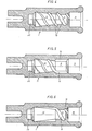
- Fig. 3 there is shown a sleeve embodiment wherein the guide portion 9 of the sleeve body 1 is provided with four locking sphere lead-in grooves 1G extending parallel to the axis of the sleeve body, the grooves extending from the widened lead-in portion 11 of the sleeve body and opening into the widened and in the shown case conically diverging portion 12 of the sleeve body.
- Fig. 4 shows another sleeve embodiment with helical lead-in grooves 13 from the lead-in portion 11 of the sleeve to the debouching region in the conically widened portion 12.
- Fig. 5 shows a third sleeve embodiment with lead-in grooves 14 extending parallel to the axis in the guide portion 9 of the sleeve, but therefrom having a helical shape ahead to its debouching region in the conically widened sleeve portion 12.
- Fig. 6 shows a fourth sleeve embodiment with lead-in grooves 15 having a helical course in the guide portion 9, but therefrom extending parallel to the axis in its debouching region in the conically widened sleeve portion 12.
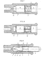
- Fig. 7 shows a sixth sleeve emodiment wherein the sleeve body 1 has a widened portion 16 which is cylindrical, in contrast to the conically widened portion 12 in the embodiments according to Figs. 3 - 6.
- This embodiment is provided with lead-in grooves 17 having a helical course in the guide portion 9 of the sleeve and debouching in the widened, cylindrical portion 16 in a diverging transition portion 18, so that the cylindrical portion is without any sphere guide grooves.
- Fig. 8 shows a sixth sleeve embodiment corresponding to the embodiment in Fig. 7 apart from the fact that it is provided with lead-in grooves 19 extending parallel to the axis in the guide portion 9 of the sleeve.
- the interior cavity 2 of the sleeve body 1 in all the illustrated embodiments terminates in a bottom portion 4 having a hole 20 for guiding receipt of the end of the rod 6, the diameter of the hole 20 corresponding to the diameter of the rod end.
- the lead-in portion 11 of the sleeve body has a cylindrical shape, with a radius which is somewhat larger than the sum of the radius of the rod 6 and the diameter of the locking spheres shown in Fig. 9.
- Fig. 9 shows a finished assembled anchoring means comprising the sleeve embodiment in Fig. 3 (having four sphere guide grooves 10) and the rod embodiment in Fig. 4.
- the rod 6, which in the illustrated case may be an insulating glass fiber bolt, is faceted according to a special grounding procedure, and the facet surfaces 8 are adapted to the radius of the locking spheres 21, so that the sum of the greatestdepth of the facet surfaces (point A in Fig. 2) from the surface of the rod and the depth of the lead-in portion 11 of the sleeve 1 from the guide portion 9 is equal to or somewhat larger than the diameter of the locking spheres.
- the binding agent 22 used is of a resin type, e.g. a two-component epoxy mass, which is adapted to the glass fiber bolt and the metal type of the sleeve body.
- the rod is moved with the locking spheres in the anchoring sleeve, and when the rod is established in correct position in the sleeve, this is vibrated for fixing of the locking spheres in correct position, i.e. in a blocking position in relation to the lead-in grooves.
- the locking spheres 21 rest against the facet surfaces 8 of the rod and against the inner wall of the widened portion 12 (or 16, 18 in the embodiment according to Figs. 7 and 8) of the sleeve 1, and the spheres are effectively kept in place by the binding agent 22 filling the annular space 23 formed between the widened portion of the sleeve body and the facet surfaces of the rod.
Landscapes
- Insulators (AREA)
- Joining Of Building Structures In Genera (AREA)
- Load-Engaging Elements For Cranes (AREA)
- Piles And Underground Anchors (AREA)
Applications Claiming Priority (2)
| Application Number | Priority Date | Filing Date | Title |
|---|---|---|---|
| NO843462 | 1984-08-31 | ||
| NO843462A NO154939C (no) | 1984-08-31 | 1984-08-31 | Forankringsanordning for en stav i et endefeste. |
Publications (1)
| Publication Number | Publication Date |
|---|---|
| EP0173665A1 true EP0173665A1 (en) | 1986-03-05 |
Family
ID=19887817
Family Applications (1)
| Application Number | Title | Priority Date | Filing Date |
|---|---|---|---|
| EP85850269A Ceased EP0173665A1 (en) | 1984-08-31 | 1985-08-28 | Anchoring means for a rod in a terminal holder |
Country Status (5)
| Country | Link |
|---|---|
| US (1) | US4663498A (da) |
| EP (1) | EP0173665A1 (da) |
| DK (1) | DK396485A (da) |
| FI (1) | FI853291L (da) |
| NO (1) | NO154939C (da) |
Families Citing this family (3)
| Publication number | Priority date | Publication date | Assignee | Title |
|---|---|---|---|---|
| US4883930A (en) * | 1987-10-30 | 1989-11-28 | Cooper Power Systems, Inc. | Switch mechanism operating rod |
| FR2626117B1 (fr) * | 1988-01-14 | 1990-06-29 | Valeo | Dispositif et procede pour le calage, suivant la direction axiale, du rotor d'une machine tournante et en particulier d'un moteur electrique, et machine tournante ainsi calee |
| US9628890B2 (en) * | 2009-06-10 | 2017-04-18 | Apple Inc. | Electronic device accessories formed from intertwined fibers |
Citations (6)
| Publication number | Priority date | Publication date | Assignee | Title |
|---|---|---|---|---|
| DE2128412A1 (de) * | 1971-06-08 | 1973-01-04 | Jordan Gmbh Georg | Verbindung zwischen stab und armatur |
| CH576690A5 (da) * | 1973-01-13 | 1976-06-15 | Trans Dev Ltd | |
| US4127741A (en) * | 1976-03-31 | 1978-11-28 | Rosenthal Technik Ag | Arrangement for elastically clamping glass fibre rods |
| DD203425A1 (de) * | 1981-12-23 | 1983-10-19 | Hermsdorf Keramik Veb | Verfahren zur herstellung einer metallarmierung, insbesondere fuer kunststoffisolatoren |
| US4435615A (en) * | 1981-02-05 | 1984-03-06 | Societe Anonyme Dite: Ceraver | Sealed end cap mounting for laminated insulator core |
| EP0125421A1 (fr) * | 1983-03-18 | 1984-11-21 | CERAVER Société anonyme dite: | Procédé de liaison de l'ailette terminale en élastomère vulcanisé d'un élément isolant avec une ferrure d'extrémité |
Family Cites Families (8)
| Publication number | Priority date | Publication date | Assignee | Title |
|---|---|---|---|---|
| FI7737A (fi) * | 1919-11-21 | Högspännisolator | ||
| DE203425C (da) * | ||||
| US974177A (en) * | 1910-02-09 | 1910-11-01 | Gen Electric | Insulator for high-tension transmission systems. |
| AT239887B (de) * | 1963-12-20 | 1965-04-26 | Radiofabrik Ingelen Porzellanf | Auf Torsion beanspruchbarer Isolator |
| GB1408861A (en) * | 1971-12-23 | 1975-10-08 | Lucas Industries Ltd | Rotary hydraulic machines |
| FR2292318A1 (fr) * | 1974-11-25 | 1976-06-18 | Ceraver | Perfectionnement a la liaison entre ame et armatures de structures comportant une ame de fibres agglomerees |
| FR2345796A2 (fr) * | 1976-02-13 | 1977-10-21 | Ceraver | Perfectionnement a la liaison entre ame et armatures de structures comportant une ame de fibres agglomerees |
| DE2611504C2 (de) * | 1976-03-18 | 1982-12-23 | WEMA Kunststoff- und Gerätebau GmbH & Co KG, Herstellung und Vertrieb von Kunststoffteilen, 8052 Moosburg | Vorrichtung zur Befestigung eines Isolatorkörpers in einer Isolatorkappe |
-
1984
- 1984-08-31 NO NO843462A patent/NO154939C/no unknown
-
1985
- 1985-08-28 EP EP85850269A patent/EP0173665A1/en not_active Ceased
- 1985-08-28 FI FI853291A patent/FI853291L/fi not_active Application Discontinuation
- 1985-08-30 DK DK396485A patent/DK396485A/da not_active Application Discontinuation
- 1985-09-03 US US06/771,690 patent/US4663498A/en not_active Expired - Fee Related
Patent Citations (6)
| Publication number | Priority date | Publication date | Assignee | Title |
|---|---|---|---|---|
| DE2128412A1 (de) * | 1971-06-08 | 1973-01-04 | Jordan Gmbh Georg | Verbindung zwischen stab und armatur |
| CH576690A5 (da) * | 1973-01-13 | 1976-06-15 | Trans Dev Ltd | |
| US4127741A (en) * | 1976-03-31 | 1978-11-28 | Rosenthal Technik Ag | Arrangement for elastically clamping glass fibre rods |
| US4435615A (en) * | 1981-02-05 | 1984-03-06 | Societe Anonyme Dite: Ceraver | Sealed end cap mounting for laminated insulator core |
| DD203425A1 (de) * | 1981-12-23 | 1983-10-19 | Hermsdorf Keramik Veb | Verfahren zur herstellung einer metallarmierung, insbesondere fuer kunststoffisolatoren |
| EP0125421A1 (fr) * | 1983-03-18 | 1984-11-21 | CERAVER Société anonyme dite: | Procédé de liaison de l'ailette terminale en élastomère vulcanisé d'un élément isolant avec une ferrure d'extrémité |
Also Published As
| Publication number | Publication date |
|---|---|
| US4663498A (en) | 1987-05-05 |
| NO154939B (no) | 1986-10-06 |
| DK396485A (da) | 1986-03-01 |
| FI853291A7 (fi) | 1986-03-01 |
| FI853291A0 (fi) | 1985-08-28 |
| NO843462L (no) | 1986-03-03 |
| FI853291L (fi) | 1986-03-01 |
| NO154939C (no) | 1987-01-14 |
| DK396485D0 (da) | 1985-08-30 |
Similar Documents
| Publication | Publication Date | Title |
|---|---|---|
| CA1256722A (en) | Expansion anchor assembly | |
| EP0040041B1 (en) | A method of producing a flemish eye on the end of a rope and a flemish eye device | |
| US4369003A (en) | Rock anchors | |
| US9931764B2 (en) | Pocketformer with releasable grout ring and tendon, tail gauge and method for using | |
| US3540763A (en) | Splice sleeve for reinforcing bars | |
| ID22070A (id) | Metode dan alat untuk menentukan ciri fluida lewat resonansi magnetik inti yang dipakai bersama instrumen-uji-formasi yang menggunakan kawat pengantar elektrik | |
| SE448925B (sv) | Sett att montera en syntethartsisolator | |
| SE421150B (sv) | Forfarande for att astadkomma en noggrann koncentrisk fasthallning av en optisk fiber i en propp | |
| AU663157B2 (en) | Mine roof expansion anchor and bail element | |
| EP0173665A1 (en) | Anchoring means for a rod in a terminal holder | |
| JP2000027822A (ja) | 特に耐震用の補足的な補強連結のための固定エレメント | |
| US4279531A (en) | End assembly for wire strand | |
| CA1242904A (en) | Guide device for a light wave conductor | |
| US6119543A (en) | Swivel insert remote control assembly and method of making same | |
| US5521996A (en) | Electrical and fiber-optic connector | |
| US5762438A (en) | Fiberglass rod end fitting | |
| US6503422B2 (en) | Method of fabricating holding devices for fiber optic connector ferrules | |
| US4526492A (en) | Anchoring element for fibrous composite materials | |
| RU92016628A (ru) | Способ жесткого соединения двух деталей с помощью связующего, в частности для заделки одной детали в другой | |
| JPS61128210A (ja) | 光フアイバケーブルと接続箱との間の接続、並びに該接続の形成法 | |
| US5735628A (en) | Rope end termination device | |
| JPS5611407A (en) | Core guide for outside wire of optical fiber | |
| SU1270804A1 (ru) | Узел соединени стеклопластикового изол тора с наконечником | |
| US4729200A (en) | Systems limited | |
| EP1002627A2 (en) | Threader stud setting tool |
Legal Events
| Date | Code | Title | Description |
|---|---|---|---|
| PUAI | Public reference made under article 153(3) epc to a published international application that has entered the european phase |
Free format text: ORIGINAL CODE: 0009012 |
|
| AK | Designated contracting states |
Kind code of ref document: A1 Designated state(s): AT BE CH DE FR GB IT LI LU NL SE |
|
| 17P | Request for examination filed |
Effective date: 19860825 |
|
| 17Q | First examination report despatched |
Effective date: 19871106 |
|
| STAA | Information on the status of an ep patent application or granted ep patent |
Free format text: STATUS: THE APPLICATION HAS BEEN REFUSED |
|
| 18R | Application refused |
Effective date: 19890102 |
|
| RIN1 | Information on inventor provided before grant (corrected) |
Inventor name: RYE, KJELL |