EP0173686B1 - A heating boiler - Google Patents
A heating boiler Download PDFInfo
- Publication number
- EP0173686B1 EP0173686B1 EP84901827A EP84901827A EP0173686B1 EP 0173686 B1 EP0173686 B1 EP 0173686B1 EP 84901827 A EP84901827 A EP 84901827A EP 84901827 A EP84901827 A EP 84901827A EP 0173686 B1 EP0173686 B1 EP 0173686B1
- Authority
- EP
- European Patent Office
- Prior art keywords
- grate
- supply pipe
- fuel
- vibrating means
- fuel particles
- Prior art date
- Legal status (The legal status is an assumption and is not a legal conclusion. Google has not performed a legal analysis and makes no representation as to the accuracy of the status listed.)
- Expired
Links
- 238000010438 heat treatment Methods 0.000 title claims abstract description 24
- 239000000446 fuel Substances 0.000 claims abstract description 60
- 239000002245 particle Substances 0.000 claims abstract description 42
- 238000002485 combustion reaction Methods 0.000 claims abstract description 36
- 239000000463 material Substances 0.000 claims abstract description 32
- 230000010355 oscillation Effects 0.000 claims description 12
- 230000001154 acute effect Effects 0.000 claims description 9
- 230000000694 effects Effects 0.000 claims description 4
- 239000008188 pellet Substances 0.000 abstract description 13
- 239000002893 slag Substances 0.000 description 6
- 239000003546 flue gas Substances 0.000 description 5
- UGFAIRIUMAVXCW-UHFFFAOYSA-N Carbon monoxide Chemical compound [O+]#[C-] UGFAIRIUMAVXCW-UHFFFAOYSA-N 0.000 description 4
- 230000001105 regulatory effect Effects 0.000 description 4
- 239000002956 ash Substances 0.000 description 3
- 239000002028 Biomass Substances 0.000 description 2
- 230000004075 alteration Effects 0.000 description 2
- 230000003534 oscillatory effect Effects 0.000 description 2
- 239000000047 product Substances 0.000 description 2
- 235000002918 Fraxinus excelsior Nutrition 0.000 description 1
- 238000007664 blowing Methods 0.000 description 1
- 239000003610 charcoal Substances 0.000 description 1
- 230000001427 coherent effect Effects 0.000 description 1
- 238000002474 experimental method Methods 0.000 description 1
- 230000002349 favourable effect Effects 0.000 description 1
- 238000009434 installation Methods 0.000 description 1
- 230000001788 irregular Effects 0.000 description 1
- 238000012423 maintenance Methods 0.000 description 1
- 238000000034 method Methods 0.000 description 1
- 239000000203 mixture Substances 0.000 description 1
- 239000010893 paper waste Substances 0.000 description 1
- 239000003415 peat Substances 0.000 description 1
- 230000000284 resting effect Effects 0.000 description 1
- 238000005245 sintering Methods 0.000 description 1
- 239000007787 solid Substances 0.000 description 1
- 239000004449 solid propellant Substances 0.000 description 1
- 239000010902 straw Substances 0.000 description 1
- 239000000725 suspension Substances 0.000 description 1
- 239000002699 waste material Substances 0.000 description 1
- 238000003466 welding Methods 0.000 description 1
- 239000002023 wood Substances 0.000 description 1
Images

Classifications
-
- F—MECHANICAL ENGINEERING; LIGHTING; HEATING; WEAPONS; BLASTING
- F23—COMBUSTION APPARATUS; COMBUSTION PROCESSES
- F23K—FEEDING FUEL TO COMBUSTION APPARATUS
- F23K3/00—Feeding or distributing of lump or pulverulent fuel to combustion apparatus
- F23K3/16—Over-feed arrangements
- F23K3/18—Spreader stokers
- F23K3/20—Spreader stokers with moving hoppers
-
- F—MECHANICAL ENGINEERING; LIGHTING; HEATING; WEAPONS; BLASTING
- F23—COMBUSTION APPARATUS; COMBUSTION PROCESSES
- F23B—METHODS OR APPARATUS FOR COMBUSTION USING ONLY SOLID FUEL
- F23B30/00—Combustion apparatus with driven means for agitating the burning fuel; Combustion apparatus with driven means for advancing the burning fuel through the combustion chamber
- F23B30/02—Combustion apparatus with driven means for agitating the burning fuel; Combustion apparatus with driven means for advancing the burning fuel through the combustion chamber with movable, e.g. vibratable, fuel-supporting surfaces; with fuel-supporting surfaces that have movable parts
-
- F—MECHANICAL ENGINEERING; LIGHTING; HEATING; WEAPONS; BLASTING
- F23—COMBUSTION APPARATUS; COMBUSTION PROCESSES
- F23B—METHODS OR APPARATUS FOR COMBUSTION USING ONLY SOLID FUEL
- F23B1/00—Combustion apparatus using only lump fuel
- F23B1/02—Combustion apparatus using only lump fuel for indirect heating of a medium in a vessel, e.g. for boiling water
- F23B1/08—Internal furnaces, i.e. with furnaces inside the vessel
-
- F—MECHANICAL ENGINEERING; LIGHTING; HEATING; WEAPONS; BLASTING
- F23—COMBUSTION APPARATUS; COMBUSTION PROCESSES
- F23B—METHODS OR APPARATUS FOR COMBUSTION USING ONLY SOLID FUEL
- F23B1/00—Combustion apparatus using only lump fuel
- F23B1/16—Combustion apparatus using only lump fuel the combustion apparatus being modified according to the form of grate or other fuel support
-
- F—MECHANICAL ENGINEERING; LIGHTING; HEATING; WEAPONS; BLASTING
- F23—COMBUSTION APPARATUS; COMBUSTION PROCESSES
- F23B—METHODS OR APPARATUS FOR COMBUSTION USING ONLY SOLID FUEL
- F23B40/00—Combustion apparatus with driven means for feeding fuel into the combustion chamber
- F23B40/06—Combustion apparatus with driven means for feeding fuel into the combustion chamber the fuel being fed along the fuel-supporting surface
-
- F—MECHANICAL ENGINEERING; LIGHTING; HEATING; WEAPONS; BLASTING
- F23—COMBUSTION APPARATUS; COMBUSTION PROCESSES
- F23B—METHODS OR APPARATUS FOR COMBUSTION USING ONLY SOLID FUEL
- F23B50/00—Combustion apparatus in which the fuel is fed into or through the combustion zone by gravity, e.g. from a fuel storage situated above the combustion zone
- F23B50/12—Combustion apparatus in which the fuel is fed into or through the combustion zone by gravity, e.g. from a fuel storage situated above the combustion zone the fuel being fed to the combustion zone by free fall or by sliding along inclined surfaces, e.g. from a conveyor terminating above the fuel bed
-
- F—MECHANICAL ENGINEERING; LIGHTING; HEATING; WEAPONS; BLASTING
- F23—COMBUSTION APPARATUS; COMBUSTION PROCESSES
- F23L—SUPPLYING AIR OR NON-COMBUSTIBLE LIQUIDS OR GASES TO COMBUSTION APPARATUS IN GENERAL ; VALVES OR DAMPERS SPECIALLY ADAPTED FOR CONTROLLING AIR SUPPLY OR DRAUGHT IN COMBUSTION APPARATUS; INDUCING DRAUGHT IN COMBUSTION APPARATUS; TOPS FOR CHIMNEYS OR VENTILATING SHAFTS; TERMINALS FOR FLUES
- F23L1/00—Passages or apertures for delivering primary air for combustion
- F23L1/02—Passages or apertures for delivering primary air for combustion by discharging the air below the fire
-
- F—MECHANICAL ENGINEERING; LIGHTING; HEATING; WEAPONS; BLASTING
- F23—COMBUSTION APPARATUS; COMBUSTION PROCESSES
- F23L—SUPPLYING AIR OR NON-COMBUSTIBLE LIQUIDS OR GASES TO COMBUSTION APPARATUS IN GENERAL ; VALVES OR DAMPERS SPECIALLY ADAPTED FOR CONTROLLING AIR SUPPLY OR DRAUGHT IN COMBUSTION APPARATUS; INDUCING DRAUGHT IN COMBUSTION APPARATUS; TOPS FOR CHIMNEYS OR VENTILATING SHAFTS; TERMINALS FOR FLUES
- F23L5/00—Blast-producing apparatus before the fire
- F23L5/02—Arrangements of fans or blowers
-
- F—MECHANICAL ENGINEERING; LIGHTING; HEATING; WEAPONS; BLASTING
- F23—COMBUSTION APPARATUS; COMBUSTION PROCESSES
- F23B—METHODS OR APPARATUS FOR COMBUSTION USING ONLY SOLID FUEL
- F23B2103/00—Adaptation of combustion apparatus for placement in or against an opening of a boiler, e.g. for replacing an oil burner
Definitions
- the present invention relates to a heating boiler having a grate onto which fuel material is supplied in particle form from a supply pipe, a vibrating means being arranged to cause the grate to vibrate in order to give the fuel particles a toss movement up from the grate depending on the oscillation effect produced by the vibrating means.
- biomass In recent years the use of biomass for energy purposes has increased considerably.
- the biomass is converted to a fuel in suitable solid form, such as pellets or brickettes.
- Fuel pellets are produced from waste-paper, raw timber products, peat, straw and mixtures of these materials, etc. and, due to their low moisture content (usually below 15%) and high density, they are intended to enable high hearth temperatures when burnt in a heating boiler.
- slag is formed due to too high a combustion temperature, in turn caused by too great and rapid supply of air.
- Fuel pellets have many advantages and valuable properties and there is therefore a great need to solve the problems mentioned above in a satisfactory manner.
- EP-A-0 048 089 describes a heating boiler for the combustion of solid fuel on a grate which is not freely suspended in the combustion chamber but instead rests on a pipe-connection at the bottom of the combustion chamber.
- a vibrator means is arranged to give the grate a vertical vibratory movement and the grate must therefore be inclined downwards so that the fuel can be spread, while special measures must be taken to retard spreading of the fuel on the inclined grate.
- the supply means is not connected with the grate or with the vibrator either.
- EP-A-0 041 860 describes a heating boiler at least as complicated in its design as that according to the specification discussed above.
- the grate is horizontal and the vibrator arranged so that the fuel particles resting on the grate are not tossed up but moved forwards without leaving the grate.
- the forward movement of the fuel particles is caused by the particles themselves pushing against each other at the filling point, and thus being forced forward. This is facilitated by the vibratory grate.
- SE-A-136 214 describes a vibratory grate for a combustion installation, which may have a supply funnel with inclined bottom plate connected to the grate.
- the fuel supply is regulated by adjusting an appropriate inclination on the bottom plate.
- the fuel supply cannot therefore be regulated simply by altering the oscillation frequency of the vibrator.
- the grate freely suspended in the combustion chamber.
- the vibrator is arranged in the combustion chamber and is connected to the grate, not to the bottom plate of the supply funnel.
- the vibrator in any of the described embodiments arranged to impart a tossing movement to the fuel particles. Instead these will only slide along the bottom plate as a coherent bed.
- the vibrator is not arranged to function as drive source to supply fuel particles to the grate via a supply pipe.
- the vibrator does not cause the fuel particles to be tossed obliquely upwards-forwards
- the bottom plate is inclined to enable the supply of fuel due to a falling effect
- the bottom plate is so arranged that, due to vibration, it influences the fuel particles in the funnel so that they fall down and slide along the inclined bottom plate.
- SE-A-168 460 relates to a method of feeding fuel along on a vibratory grate with inclined grate surface, while the amplitude is kept constant. No statement is given about free suspension of the grate.
- US-A-4 250 818 describes a vibrating combustion bed which is not freely suspended in a combustion chamber.
- a primary object of the present invention is to solve the problems mentioned above in particular in the burning of pellets and similar fuel material in a heating boiler and thus considerably improve the efficiency of the heating boiler by creating conditions in order to obtain good and uniform combustion and high hearth temperature without the pellets and the combusted material becoming bonded together to a slag which in turn gradually throttles the supply of primary air to the hearth.
- the supply pipe is mechanically connected to the grate and arranged to freely support the grate, which is thus freely suspended in the combustion chamber without contact with the bottom or walls of the combustion chamber; that the supply pipe is resiliently suspended on a front door of the heating boiler by means of cross-stays secured to the supply pipe, brackets secured to the front door, and springs arranged between the cross-stays and brackets; and that the vibrating means is mounted to the supply pipe such that its centre line forms an acute angle with the direction of transport of fuel material and arranged to produce a rectilinear movement coinciding with said centre line, the vibrating means being arranged to continuously impart to the fuel particles a toss movement obliquely upwards and forwards in the supply pipe and on the grate whereby the fuel particles move onto the grate and towards the end of the grate opposite the supply pipe.
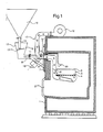
- Figure 1 shows schematically a heating boiler in section which is provided with a means according to the present invention.
- FIG 2 shows the heating boiler according to Figure 1 seen from the front with certain parts removed.
- the drawings show schematically a heating boiler 1 which may be of conventional type.
- the heating boiler has a combustion chamber 2 into which the fuel material is introduced and combusted.
- the flue gases are withdrawn through a flue-gas pipe in known manner.
- the heating boiler is equipped with a means according to the present invention which, in the embodiment shown, comprises a grate 3 located in the combustion chamber, said grate having a bottom 4 and surrounding side walls 5.
- the grate bottom is provided with through-holes or openings permitting air to flow through the grate in direction from below.
- the grate is arranged horizontally but may in certain cases be upwardly inclined in order to reduce the speed at which the particles move.
- the grate 3 is supported by supporting means permitting it to be brought into oscillation at a suitable frequency by means of a vibrating means so that the fuel material, which is in piece or particle form, is brought into a toss movement obliquely up from the bottom 4 of the grate in forward direction.
- the fuel material is supplied into the combustion chamber 2 through a supply pipe 6 which in the embodiment shown simultaneously serves as a part of the supporting means for supporting the grate which is thereby freely suspended in the combustion chamber without having any contact with the bottom or walls of the combustion chamber.
- a horizontal portion of the supply pipe 6 is passed through an aperture in a vertical door 7 which is detachably mounted to the front of the heating boiler.
- the supply pipe terminates in the combustion chamber with a vertical portion having an inclined guide plate 8 which ends above the bottom of the grate so that the fuel material can fall freely onto the grate.
- brackets 9 are secured to the front door 7 which, via springs 10, support two cross-stays 11 attached to the supply pipe 6.
- the grate 3 and supply pipe 6 are springingly or resiliently suspended at the front door 7 via the cross-stays 11 and brackets 9, and the springs 10 connecting the cross-stays 11 and brackets 9.
- the supply pipe 6 has a hopper 12 supplied with fuel material from a store 13 which may consist of a separately suspended funnel immediately above the hopper 12 as shown in the drawings, or a silo or the like having suitable feeding means connected to the supply pipe 6.
- the funnel 13 has a mouth pipe 14, vertically adjustable to cooperate with an inclined plate 15 below, which is arranged in the hopper 12 to regulate the feeding rate of the fuel material.
- the rearwardly inclined plate 15 defines a gap 16 with the opposite wall of the hopper.
- the size of this gap 16 may be adjustable if desired, to offer an additional possibility of adjusting the correct feeding rate of the fuel material.
- Such control means in the form of the mouth pipe 14 and gap 16 can suitably be controlled and adjusted by one or more other functions of the heating boiler and possibly by external factors.
- a pipe 17 for the supply of air is passed through the front door 7, parallel to the supply pipe 6, the air-supply pipe 17 being connected to a fan motor 18 which can be started when desired to forcedly blow in primary air, for instance for continuous operation or when the heating boiler starts and for a suitable period thereafter.
- the air-supply pipe extends below the grate 3 and ends at the inner end portion of the grate and below the bottom 4 of the grate, whereby airforthe combustion flows in a favourable manner in direction to the place for the supplying of the fuel material.
- a vibrating means 19 is arranged below the supply pipe 6 and in direct mechanical connection therewith.
- the vibrating means is arranged to bring the supply pipe 6 and thus also the grate 3 which is rigidly connected to the supply pipe by means of welding or rivet or screw joints, for instance, into oscillation or reciprocal movement with a suitable frequency and amplitude, whereby the oscillating movement is transmitted from the outer end of the supply pipe comprising the hopper 12, to the inner end of the grate.
- the fuel material in particle form entering the hopper 12 will thus be fed forward through the supply pipe 6 and further out onto and across the grate where it is gradually combusted.
- the fuel particles thus acquire a toss movement such that they the whole time are moved up from the support, i.e.
- the bottom of the supply pipe and the bottom 4 of the grate forwards in relation to the support, in a manner particularly conducive to the combustion. Since the fuel particles are constantly in motion, they will hit against each other and against the grate so that combusted material is removed from the particles and new material exposed for the continued combustion. Furthermore, the particles have no chance of sintering together or of forming slag since they are in constant movement on the grate.
- the flow of the fuel material is determined by the frequency and oscillatory effect of the vibrating means.
- the oscillation amplitude can be regulated steplessly. Increased oscillation amplitude thus means that the fuel particles are tossed up in a higher path in relation to the grate.
- the movement course of the fuel particles can be improved still further by directing the air for the combustion in below the grate such that the air flows up through the apertures in the grate as in the embodiment shown schematically. An excess of air normal for the combustion is thus utilized.
- the air flow through the grate can be further increased by feeding back some of the flue-gas leaving, whereby this portion of flue-gas is mixed with a quantity of air suitably adjusted for the combustion (including said excess).
- Any known vibrating means which provides a rectilinear oscillatory movement can be used to effect vibration of the grate and supply pipe and may comprise magnet vibrator, unbalanced motors or mechanical means such as crank and excenter.
- a magnet vibrator is used, the oscillations being produced by an electro-magnet supplied with alternating current.
- One half-period of the supply voltage is normally cut off by means of a uni-directional rectifier in order to obtain a lower periodicity, e.g. 3000 oscillations per minute.
- An advantage of the magnet vibrator is that it functions extremely reliably.
- the flow of material can be controlled and regulated steplessly during operation since an alteration in the control signal results practically instantaneously in a corresponding alteration in the flow of material.
- the magnet vibrator is mounted so that its centre line forms an acute angle with the direction of transport of the fuel material, as can be seen from the drawings, thus setting the conveyor, i.e. the supply pipe 6 and grate 3, in rectilinear oscillation, provided the grate supply, pipe and magnet vibrator are correctly balanced in relation to each other and the journalling points.
- Said acute angle between the centre line (the direction of vibration) of the vibrating means and the direction of transport of the fuel material may be varied depending on the desired toss angle (corresponding to said acute angle) of the fuel material.
- a suitable range of the acute angle is about 25°-40°, the preferred range being 30°-35°.
- the vibrating means is suitably adjustable so that the direction of vibration and thereby the acute angle and toss angle may be amended to values desired.
- the magnet vibrator or other vibrating means has the double function to serve as drive source to feed the fuel particles to the grate and also to set the grate in oscillations which result in that the fuel particles are brought in a toss movement obliquely upwards so that they move into the grate towards its far end at the same time as they are relieved from burnt material by hitting against each other and against the grate, thus essentially improving the combustion and increasing the efficiency of the heating boiler.
- the supply of the primary air is preferably carried out by forced blowing by means of the fan motor 18, ensuring an uniform and complete combustion at the same time as the fuel particles will be carried and further tossed around by the air flowing through the grate when they are hit by the air jets.
- the ash will accompany the flue-gas upwards and then be collected at the bottom of the combustion chamber. Secondary air may be added at a point above the grate, particularly if the fuel particles contain volatile material which would otherwise disappear without being burnt.
- An ignition device 20 is preferably arranged in the vicinity of the grate in order to ignite the fuel material when the heating boiler is started. When the correct boiler temperature has been reached the supply of fuel particles is reduced by control means to zero or to such a low level that maintenance combustion can be maintained in the grate until the boiler temperature has fallen and a signal is again given for full combustion.
- a net or the like may be arranged on the roof of the grate to prevent fuel particles from being carried outside the grate.
- the means according to the invention has been developed with the problem of burning pellets particularly in mind. However, it offers valuable advantages when burning other fuel materials in particle form and should not therefore be considered to be limited to pellets.
- the means according to the invention comprising grate and vibrating means and supply pipe, i.e. grate and supply pipe built together and journalled in the manner described and actuated by a common vibrator, forms a simple additional unit for easy rebuilding of conventional heating boilers to which feeding means are connected from an adjacent stock of pellets.
Landscapes
- Engineering & Computer Science (AREA)
- Chemical & Material Sciences (AREA)
- Combustion & Propulsion (AREA)
- Mechanical Engineering (AREA)
- General Engineering & Computer Science (AREA)
- Physics & Mathematics (AREA)
- Thermal Sciences (AREA)
- Solid-Fuel Combustion (AREA)
- Fluidized-Bed Combustion And Resonant Combustion (AREA)
Priority Applications (1)
| Application Number | Priority Date | Filing Date | Title |
|---|---|---|---|
| AT84901827T ATE35309T1 (de) | 1983-04-26 | 1984-04-16 | Kessel. |
Applications Claiming Priority (2)
| Application Number | Priority Date | Filing Date | Title |
|---|---|---|---|
| SE8302335A SE436298B (sv) | 1983-04-26 | 1983-04-26 | Anordning vid en vermepanna anordning vid en vermepanna |
| SE8302335 | 1983-04-26 |
Publications (2)
| Publication Number | Publication Date |
|---|---|
| EP0173686A1 EP0173686A1 (en) | 1986-03-12 |
| EP0173686B1 true EP0173686B1 (en) | 1988-06-22 |
Family
ID=20350955
Family Applications (1)
| Application Number | Title | Priority Date | Filing Date |
|---|---|---|---|
| EP84901827A Expired EP0173686B1 (en) | 1983-04-26 | 1984-04-16 | A heating boiler |
Country Status (8)
| Country | Link |
|---|---|
| US (1) | US4610208A (da) |
| EP (1) | EP0173686B1 (da) |
| CA (1) | CA1227090A (da) |
| DE (1) | DE3472291D1 (da) |
| DK (1) | DK162798C (da) |
| FI (1) | FI83363C (da) |
| SE (1) | SE436298B (da) |
| WO (1) | WO1984004374A1 (da) |
Cited By (1)
| Publication number | Priority date | Publication date | Assignee | Title |
|---|---|---|---|---|
| CN109140490A (zh) * | 2018-09-05 | 2019-01-04 | 高亚贵 | 一种用于生物质燃烧机的鼓风装置 |
Families Citing this family (8)
| Publication number | Priority date | Publication date | Assignee | Title |
|---|---|---|---|---|
| GB8722988D0 (en) * | 1987-09-30 | 1987-11-04 | Wells & Sons A J | Solid fuel burner |
| PT1188022E (pt) * | 1999-05-21 | 2010-06-21 | Barlow Projects Inc | Sistema melhorado para queima de combustíveis em massa |
| RU2206823C1 (ru) * | 2002-04-08 | 2003-06-20 | Иванов Виктор Евгеньевич | Топочное устройство |
| US6868777B1 (en) * | 2003-07-09 | 2005-03-22 | Mike Higgins | Cooker and smoker apparatus and method of smoke generation, recirculation, and exhaust |
| DE102008026836B4 (de) * | 2008-06-05 | 2010-04-08 | Kurt Himmelfreundpointner | Verfahren und Vorrichtung zur Materialförderung durch eine Ofenwand |
| CN107355980B (zh) * | 2017-07-17 | 2024-06-04 | 浙江天翔环保设备有限公司 | 一种燃烧效率高且防摔的锅炉 |
| US11026543B2 (en) | 2018-03-07 | 2021-06-08 | Onward Multi-Corp. Inc. | Pellet-fired cooking apparatus |
| CN112066554B (zh) * | 2020-09-21 | 2021-05-21 | 金华智果智能科技有限公司 | 一种利用生物质能对热泵进行能源输送的方法 |
Family Cites Families (8)
| Publication number | Priority date | Publication date | Assignee | Title |
|---|---|---|---|---|
| SE136214C1 (da) * | ||||
| SE168460C1 (da) * | ||||
| US4007697A (en) * | 1975-10-02 | 1977-02-15 | Prill Manufacturing Company | Stoker actuated coal burning apparatus |
| CH622084A5 (da) * | 1977-07-14 | 1981-03-13 | Schenck Ag Carl | |
| US4389978A (en) * | 1980-06-10 | 1983-06-28 | Parkinson Cowan Gwb Limited | Grates |
| DE3168311D1 (en) * | 1980-08-19 | 1985-02-28 | Suxe Combustion Ltd | Furnace and boiler combination |
| US4491077A (en) * | 1980-08-20 | 1985-01-01 | Richardsons Westgarth & Co., Ltd. | Vibrating hearth burners |
| DE3041025C2 (de) * | 1980-10-31 | 1985-05-15 | Günther 5628 Heiligenhaus Unger | Verfahren und Vorrichtung zur Verbrennung von insbesondere aschereichen Brennstoffen |
-
1983
- 1983-04-26 SE SE8302335A patent/SE436298B/sv not_active IP Right Cessation
-
1984
- 1984-04-16 EP EP84901827A patent/EP0173686B1/en not_active Expired
- 1984-04-16 US US06/704,311 patent/US4610208A/en not_active Expired - Fee Related
- 1984-04-16 DE DE8484901827T patent/DE3472291D1/de not_active Expired
- 1984-04-16 WO PCT/SE1984/000145 patent/WO1984004374A1/en not_active Ceased
- 1984-04-19 CA CA000452460A patent/CA1227090A/en not_active Expired
- 1984-12-11 DK DK592984A patent/DK162798C/da not_active IP Right Cessation
-
1985
- 1985-05-20 FI FI851995A patent/FI83363C/fi not_active IP Right Cessation
Cited By (1)
| Publication number | Priority date | Publication date | Assignee | Title |
|---|---|---|---|---|
| CN109140490A (zh) * | 2018-09-05 | 2019-01-04 | 高亚贵 | 一种用于生物质燃烧机的鼓风装置 |
Also Published As
| Publication number | Publication date |
|---|---|
| CA1227090A (en) | 1987-09-22 |
| FI83363B (fi) | 1991-03-15 |
| FI851995L (fi) | 1985-05-20 |
| DK162798C (da) | 1992-04-27 |
| EP0173686A1 (en) | 1986-03-12 |
| FI83363C (fi) | 1991-06-25 |
| SE8302335D0 (sv) | 1983-04-26 |
| WO1984004374A1 (en) | 1984-11-08 |
| DE3472291D1 (en) | 1988-07-28 |
| FI851995A0 (fi) | 1985-05-20 |
| DK592984D0 (da) | 1984-12-11 |
| DK592984A (da) | 1984-12-11 |
| DK162798B (da) | 1991-12-09 |
| SE436298B (sv) | 1984-11-26 |
| SE8302335L (da) | 1984-10-27 |
| US4610208A (en) | 1986-09-09 |
Similar Documents
| Publication | Publication Date | Title |
|---|---|---|
| US4528917A (en) | Solid fuel burner | |
| CA1062012A (en) | Apparatus for producing combustible gases from carbonaceous materials | |
| US4610208A (en) | Vibrating grate in a heating boiler | |
| US3841242A (en) | Apparatus for burning waste matter | |
| US4434724A (en) | Overbed distributor for feeding dual solid fuels to a stoker furnace | |
| US4592292A (en) | Method and apparatus for activating large particles | |
| US4589355A (en) | Particulate waste product combustion system | |
| US5070798A (en) | Pellet burner appliances and burners therefor | |
| JPH01500758A (ja) | 固体燃料からガスを製造する装置 | |
| JPH01503083A (ja) | 交互に固定の棒と往復動自在の棒とを配してなる火格子を有し、調整の融通性を増強した、特に都市ごみ用に使用するための炉 | |
| EP0064505B1 (en) | Fluidized bed combustion apparatus | |
| JPH03501997A (ja) | 発電プラントの燃料としてゴミ燃料を使用する装置のゴミ燃料処理システム | |
| CA1184439A (en) | Vibrating hearth burners | |
| US4056069A (en) | Method of burning refuse | |
| JPS59217406A (ja) | 流動床燃焼装置 | |
| SE8602959D0 (sv) | Kraftanleggning med forbrenning av ett brensle i en brennkammare med en fluidiserad bedd | |
| US4693234A (en) | Apparatus for and method of burning and/or thermally decomposing fuel, especially solid fuels | |
| US2873702A (en) | Shaking grates especially for burning different kinds of fuel | |
| GB2093961A (en) | Solid fuel burners | |
| US2204317A (en) | Combustion apparatus | |
| US2895436A (en) | Fuel burning apparatus | |
| US2289434A (en) | Stoker | |
| WO1988007649A1 (en) | Solid fuel furnaces | |
| US686053A (en) | Automatic stoker. | |
| US583552A (en) | siieppard |
Legal Events
| Date | Code | Title | Description |
|---|---|---|---|
| PUAI | Public reference made under article 153(3) epc to a published international application that has entered the european phase |
Free format text: ORIGINAL CODE: 0009012 |
|
| 17P | Request for examination filed |
Effective date: 19850513 |
|
| AK | Designated contracting states |
Kind code of ref document: A1 Designated state(s): AT BE CH DE FR GB LI LU NL SE |
|
| 17Q | First examination report despatched |
Effective date: 19860925 |
|
| GRAA | (expected) grant |
Free format text: ORIGINAL CODE: 0009210 |
|
| AK | Designated contracting states |
Kind code of ref document: B1 Designated state(s): AT BE CH DE FR GB LI LU NL SE |
|
| PG25 | Lapsed in a contracting state [announced via postgrant information from national office to epo] |
Ref country code: NL Effective date: 19880622 Ref country code: LI Effective date: 19880622 Ref country code: FR Free format text: THE PATENT HAS BEEN ANNULLED BY A DECISION OF A NATIONAL AUTHORITY Effective date: 19880622 Ref country code: CH Effective date: 19880622 Ref country code: BE Effective date: 19880622 Ref country code: AT Effective date: 19880622 |
|
| REF | Corresponds to: |
Ref document number: 35309 Country of ref document: AT Date of ref document: 19880715 Kind code of ref document: T |
|
| PG25 | Lapsed in a contracting state [announced via postgrant information from national office to epo] |
Ref country code: SE Effective date: 19880630 |
|
| REF | Corresponds to: |
Ref document number: 3472291 Country of ref document: DE Date of ref document: 19880728 |
|
| REG | Reference to a national code |
Ref country code: CH Ref legal event code: PL |
|
| NLV1 | Nl: lapsed or annulled due to failure to fulfill the requirements of art. 29p and 29m of the patents act | ||
| EN | Fr: translation not filed | ||
| PLBE | No opposition filed within time limit |
Free format text: ORIGINAL CODE: 0009261 |
|
| STAA | Information on the status of an ep patent application or granted ep patent |
Free format text: STATUS: NO OPPOSITION FILED WITHIN TIME LIMIT |
|
| PG25 | Lapsed in a contracting state [announced via postgrant information from national office to epo] |
Ref country code: LU Free format text: LAPSE BECAUSE OF NON-PAYMENT OF DUE FEES Effective date: 19890430 |
|
| 26N | No opposition filed | ||
| PGFP | Annual fee paid to national office [announced via postgrant information from national office to epo] |
Ref country code: GB Payment date: 19920320 Year of fee payment: 9 |
|
| PGFP | Annual fee paid to national office [announced via postgrant information from national office to epo] |
Ref country code: DE Payment date: 19920614 Year of fee payment: 9 |
|
| PG25 | Lapsed in a contracting state [announced via postgrant information from national office to epo] |
Ref country code: GB Effective date: 19930416 |
|
| GBPC | Gb: european patent ceased through non-payment of renewal fee |
Effective date: 19930416 |
|
| PG25 | Lapsed in a contracting state [announced via postgrant information from national office to epo] |
Ref country code: DE Effective date: 19940101 |