EP0173761A1 - Leistungsgenerator für einen Ultraschallwandler - Google Patents
Leistungsgenerator für einen Ultraschallwandler Download PDFInfo
- Publication number
- EP0173761A1 EP0173761A1 EP84110500A EP84110500A EP0173761A1 EP 0173761 A1 EP0173761 A1 EP 0173761A1 EP 84110500 A EP84110500 A EP 84110500A EP 84110500 A EP84110500 A EP 84110500A EP 0173761 A1 EP0173761 A1 EP 0173761A1
- Authority
- EP
- European Patent Office
- Prior art keywords
- ultrasonic transducer
- winding
- transformer
- capacitance
- measuring device
- Prior art date
- Legal status (The legal status is an assumption and is not a legal conclusion. Google has not performed a legal analysis and makes no representation as to the accuracy of the status listed.)
- Granted
Links
- 238000004804 winding Methods 0.000 claims abstract description 38
- 230000008878 coupling Effects 0.000 claims abstract description 11
- 238000010168 coupling process Methods 0.000 claims abstract description 11
- 238000005859 coupling reaction Methods 0.000 claims abstract description 11
- 230000005291 magnetic effect Effects 0.000 claims abstract description 4
- 239000003990 capacitor Substances 0.000 claims description 6
- 238000002604 ultrasonography Methods 0.000 description 26
- 208000006568 Urinary Bladder Calculi Diseases 0.000 description 4
- 238000010586 diagram Methods 0.000 description 4
- 230000000694 effects Effects 0.000 description 4
- 230000010363 phase shift Effects 0.000 description 3
- 238000004140 cleaning Methods 0.000 description 2
- 230000001105 regulatory effect Effects 0.000 description 2
- 239000000523 sample Substances 0.000 description 2
- 239000004575 stone Substances 0.000 description 2
- XLYOFNOQVPJJNP-UHFFFAOYSA-N water Substances O XLYOFNOQVPJJNP-UHFFFAOYSA-N 0.000 description 2
- 208000000913 Kidney Calculi Diseases 0.000 description 1
- 206010029148 Nephrolithiasis Diseases 0.000 description 1
- 230000032683 aging Effects 0.000 description 1
- 230000005540 biological transmission Effects 0.000 description 1
- 239000000919 ceramic Substances 0.000 description 1
- 239000004020 conductor Substances 0.000 description 1
- 239000000356 contaminant Substances 0.000 description 1
- 230000006378 damage Effects 0.000 description 1
- 239000003814 drug Substances 0.000 description 1
- 239000013013 elastic material Substances 0.000 description 1
- 238000005516 engineering process Methods 0.000 description 1
- 238000010438 heat treatment Methods 0.000 description 1
- 239000007788 liquid Substances 0.000 description 1
- 238000004519 manufacturing process Methods 0.000 description 1
- 238000005259 measurement Methods 0.000 description 1
- 238000000034 method Methods 0.000 description 1
- 238000012544 monitoring process Methods 0.000 description 1
- 230000010355 oscillation Effects 0.000 description 1
- 230000000284 resting effect Effects 0.000 description 1
- 230000000717 retained effect Effects 0.000 description 1
- 238000001356 surgical procedure Methods 0.000 description 1
- 210000003708 urethra Anatomy 0.000 description 1
- 238000003466 welding Methods 0.000 description 1
Images


Classifications
-
- B—PERFORMING OPERATIONS; TRANSPORTING
- B06—GENERATING OR TRANSMITTING MECHANICAL VIBRATIONS IN GENERAL
- B06B—METHODS OR APPARATUS FOR GENERATING OR TRANSMITTING MECHANICAL VIBRATIONS OF INFRASONIC, SONIC, OR ULTRASONIC FREQUENCY, e.g. FOR PERFORMING MECHANICAL WORK IN GENERAL
- B06B1/00—Methods or apparatus for generating mechanical vibrations of infrasonic, sonic, or ultrasonic frequency
- B06B1/02—Methods or apparatus for generating mechanical vibrations of infrasonic, sonic, or ultrasonic frequency making use of electrical energy
- B06B1/0207—Driving circuits
- B06B1/0223—Driving circuits for generating signals continuous in time
- B06B1/0238—Driving circuits for generating signals continuous in time of a single frequency, e.g. a sine-wave
- B06B1/0246—Driving circuits for generating signals continuous in time of a single frequency, e.g. a sine-wave with a feedback signal
- B06B1/0253—Driving circuits for generating signals continuous in time of a single frequency, e.g. a sine-wave with a feedback signal taken directly from the generator circuit
-
- H—ELECTRICITY
- H03—ELECTRONIC CIRCUITRY
- H03L—AUTOMATIC CONTROL, STARTING, SYNCHRONISATION OR STABILISATION OF GENERATORS OF ELECTRONIC OSCILLATIONS OR PULSES
- H03L7/00—Automatic control of frequency or phase; Synchronisation
- H03L7/02—Automatic control of frequency or phase; Synchronisation using a frequency discriminator comprising a passive frequency-determining element
Definitions
- Ultrasonic transducers are used in many applications in which a desired effect can be achieved with the power of an ultrasonic wave or an ultrasonic vibration.
- An example are cleaning devices in which a cleaning liquid is excited to ultrasonic vibrations by an ultrasonic transducer, as a result of which even adhering contaminants are detached from the surface of immersed objects.
- Another example is ultrasonic welding equipment, which uses the heat loss that occurs in high-intensity ultrasonic vibrations in elastic materials.
- ultrasonic transducers are e.g. B. known for the transmission of directed, modulated ultrasound waves in water, which can be used for transmitting messages or locating ships under water.
- ultrasound transducers are used, for example, to destroy bladder and kidney stones, since ultrasound waves of high intensity can be guided relatively easily with waveguides through natural body openings (e.g. the urethra) to the stones to be destroyed, which means that the stones can be removed without major surgery.
- body openings e.g. the urethra
- Ultrasonic transducers are known as electro-mechanical transducers and can be constructed according to various principles. For high outputs, ceramic disks are used, which work according to the reverse piezoelectric effect.
- ultrasonic transducers are coupled to a mechanical resonance arrangement.
- high output power with good efficiency can only be achieved if the arrangement is exactly at the resonance frequency of the mecha African arrangement or very close to it.
- the electrical power with which the ultrasonic transducer is fed must therefore be supplied very precisely with the working frequency of the mechanical arrangement. Since the resonance frequency of the arrangement can change during operation, for example as a result of heating or a change in load, or as a result of aging phenomena over the course of its service life, the power generator which controls the ultrasound transducer must be regulated by the resonance conditions of the mechanical arrangement.
- phase measuring devices are used which measure the phase difference between the voltage fed in at the ultrasound transducer and the current fed in. The frequency of the power generator is readjusted from the output signal of the ' phase measuring device so that the voltage and current at the ultrasound transducer adhere to a predetermined phase shift, ie in general they are in phase if possible.
- the High-Frequency Generator for the Ultrasonic Lithotrite is a high-frequency power generator that feeds an ultrasound probe for the destruction of bladder stones.
- the high-frequency generator contains a voltage-controlled oscillator, which is referred to in the Anglo-American as “voltage-controlled oscillator” or VCO.
- VCO voltage-controlled oscillator
- This VCO can be tuned in frequency with an applied voltage.
- the high frequency output voltage of the oscillator is amplified by a power amplifier and fed to the ultrasonic transducer.
- a phase measuring device measures the phase difference at the output of the amplifier between the current which flows through the ultrasound transducer and the voltage which is present at the ultrasound transducer and forwards the output signal to the VCO. As a result, the frequency of the VCO is continuously tuned to the resonance condition.
- an ultrasonic transducer has an equivalent circuit diagram, which is constructed as a series resonant circuit from a capacitance, an inductance and an ohmic resistance.
- a capacitance the so-called quiescent capacitance of the ultrasonic transducer, is parallel to this series resonant circuit.
- the value of the ohmic resistance in the series resonant circuit changes. This resistance is smallest at the lowest load, and its value also increases with increasing load.
- the ultrasound transducer is spatially separated from the power generator, for example in the case of ultrasound bladder stone crushing.
- the distance must be one Supply line are bridged, the capacity of which results in a further parallel capacity to the ultrasonic transducer.
- the electrical impedance of the entire ultrasonic transducer connected to the power generator, including the supply line, therefore no longer has a phase angle of zero when the mechanical arrangement actually resonates.
- the phase angle of the electrical impedance does not even have a constant value at the resonance frequency of the mechanical arrangement when the load changes.
- a fixed setting of the phase control can therefore result in the optimal output power for a maximum of a single load value.
- the phase control influences the VCO so that the frequency runs out of the resonance of the mechanical arrangement more or less.
- the locus of the input impedance of an ultrasonic transducer with quiescent capacitance and supply capacitance is not symmetrical to the real axis in the region of the resonance frequency. It becomes more asymmetrical the greater the load and can move so strongly into the capacitive half-plane that in the area of the resonance loop there is no longer any value at which the phase between current and voltage has the value to which the phase control is set . With such a load, the vibration 'breaks off, the ultrasonic transducer no longer outputs power.
- the invention has for its object to provide a power generator for an ultrasonic transducer in which the phase control can be set so that the maximum possible output power of the power generator and the highest possible vibration stability in the event of load fluctuations are achieved simultaneously.
- the second input signal of the phases Measuring device with which the phase of the current through the ultrasonic transducer is measured slides from a transformer with three windings.
- the first winding of the transmitter flows the current that is supplied to the ultrasound transducer as a whole, or a proportional portion thereof.
- a current flows through the second winding of this transformer, which current is equal or proportional to the reactive current caused by the supply capacitance and the rest capacitance of the ultrasonic transducer.
- the first and the second winding are polarized so that their magnetic effects on the core of the transmitter are different.
- a magnetic voltage acts on the core, which is proportional to the pure active current that flows through the effective resistance in the replacement circuit diagram of the ultrasonic transducer.
- a signal can therefore be taken from a third winding on this transformer which is proportional to the pure active current of the ultrasonic transducer and in particular has its phase. If this signal is fed to the phase measuring device as a phase signal for the current of the ultrasound transducer, the resonance monitoring can be carried out without the disturbing influences of the lead inductance and the quiescent capacitance of the ultrasound transducer.
- the phase between the voltage at the ultrasonic transducer and its active current can be regulated constantly and even exactly to zero degrees regardless of the load.
- the first winding of the transmitter is connected in series with the connected ultrasound transducer.
- a capacitor is connected in series with the second winding of the transmitter.
- the two series circuits thus formed are connected in parallel and directly or via known ones Coupling circuits connected to the output of the power amplifier, the capacitor in series with the second winding being dimensioned such that the ratio of its capacitance to the sum of the supply capacitance and the rest capacitance of the ultrasound transducer is approximately inversely proportional to the ratio of the win of the second and the first winding. With this dimensioning, the effects of the supply and quiescent capacities are almost completely compensated for the phase measurement in the core of the transformer.
- the capacitance of the capacitor is selected approximately as large as the sum of the supply capacitance and the rest capacitance of the ultrasound transducer and if the first and the second winding of the transmitter have the same number of turns, a further advantageous embodiment of the invention is obtained.
- Fig. 1 the block diagram of a power generator according to the invention with the transformer consisting of three windings is shown.
- the VCO 15 feeds a power amplifier 16, at whose output a coupling quadrupole 11 is connected in this example.
- a coupling quadrupole can be used in a known manner, e.g. the amplifier works in the push-pull principle and the outputs of the two amplifier halves must be connected together. But it can also be used to adjust performance.
- Such a coupling quadrupole is generally realized as a transformer with a high coupling factor.
- the series circuit comprising the ultrasound transducer 8 and the first winding 4 of the transmitter 3 is first connected to the output of the coupling quadrupole which may be used. In addition to the ultrasonic transducer 8, there is also the supply capacitance 6.
- the series circuit comprising the second winding 5 of the transformer 3 and the capacitance 10 is also connected.
- the voltage U is tapped off as the first input signal for the phase measuring device 1 at the output of the coupling quadrupole 11.
- a third winding 2 is also arranged on the core 9 of the transformer 3. The second input signal for the phase measuring device 1 is tapped from it.
- the phase measuring device 1 can operate according to any of the known principles. It only has to establish a suitable relationship between its output voltage and the phase difference between the two input signals.
- the phase measuring device is generally a setpoint comparator and contain a control amplifier with a suitable characteristic so that the control loop operates stably and regulates the phase difference between the two input signals of the phase measuring device constantly to the predetermined target value.
- FIG. 2 shows, in a Smith chart, location curves of the input impedance Z of an ultrasound transducer with a feed in the range of the resonance frequency, as it is e.g. would be measured between terminals 20 and 21 in FIG.
- the parameter of the curves is the load.
- the locus 22 with the largest diameter describes the unloaded case.
- the real parts of the impedance contained in this locus can only be attributed to the intrinsic losses of the ultrasonic transducer and the coupled mechanical resonance arrangement.
- the local curves with smaller diameters arise with increasing load on the ultrasonic transducer.
- the resonance frequency for mechanical resonance is marked with a circle on each locus. With this frequency, the power generator would have to deliver its power each time in order to generate the maximum possible ultrasound power with every load.
- the electrical input impedance of the ultrasonic transducer has a different phase angle at the mechanical resonance frequency with each load. If the phase control of a power generator is therefore set to a constant phase angle between voltage and current in the ultrasound transducer without the configuration according to the invention, then this control can only give the maximum possible ultrasound power when there is a load. 2 shows this case for an example.
- the dashed curve 23 in the Smith chart is a constant phase impedance curve. If the phase control is set to the value of this example, the ultrasonic transducer is only operated with the locus curve 24 in the case of the mechanical resonance in the third load case shown but not all other burdens.
- Fig. 2 shows that from a certain load, the locus of the input impedance Z no longer intersect the set phase angle.
- a power generator without the embodiment according to the invention no longer outputs any power, and the ultrasonic oscillation breaks off. Such a generator can therefore only ever be set to a compromise between performance under a certain load and stability.
- a power generator according to the invention avoids the effects of the supply capacitance and the idle capacitance of the ultrasonic transducer, because the reactive currents associated therewith in the measuring branch of the current phase are compensated for with the aid of the proposed measure.
- a generator with the features of the invention can be optimally adjusted to the mechanical resonance of the ultrasonic transducer, and this setting is retained with every load.
- the ultrasonic vibration breaks off with optimal power setting under no load.
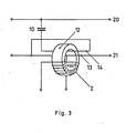
- the core of the transformer is designed as a ring core, which is particularly low in stray and thus makes it possible to implement small inductances for the first and the second winding.
- the first and the second winding are each designed as only one turn, which in the case of the toroidal core means one conductor only led once through the toroidal core.
Landscapes
- Engineering & Computer Science (AREA)
- Mechanical Engineering (AREA)
- Apparatuses For Generation Of Mechanical Vibrations (AREA)
- Transducers For Ultrasonic Waves (AREA)
- General Electrical Machinery Utilizing Piezoelectricity, Electrostriction Or Magnetostriction (AREA)
Abstract
Description
- Ultraschallwandler werden in vielen Anwendungsfällen verwendet, in denen eine gewünschte Wirkung mit der Leistung einer Ultraschallwelle oder einer Ultraschallschwingung erzielt werden kann. Ein Beispiel sind Reinigungsgeräte, bei denen eine Reinigungsflüssigkeit durch einen Ultraschallwandler zu Ultraschallschwingungen angeregt wird, wodurch auch festhaftende Verunreinigungen von der Oberfläche eingetauchter Gegenstände abgelöst werden. Ein weiteres Beispiel sind Ultraschall-Schweißgeräte, bei denen die Verlustwärme genutzt wird, die bei Ultraschallschwingungen hoher Intensität in elastisehen Materialien auftritt. In der Hochfrequenztechnik sind Ultraschallwandler z. B. zur Aussendung von gerichteten, modulierten Ultrasohallwellen in Wasser bekannt, was zur Nachrichtenübertragung oder Ortung von Schiffen unter Wasser verwendet werden kann. In der Medizin werden Ultraschallwandler beispielsweise zur Zerstörung von Blasen- und Nierensteinen verwendet, da sich Ultraschallwellen hoher Intensität mit Wellenleitern relativ einfach durch natürliche Körperöffnungen (z.B. die Harnröhre) an die zu zerstörenden Steine heranführen lassen, wodurch die Steine ohne größere Operation entfernbar sind.
- Ultraschallwandler werden als elektro-mechanische Wandler bezeichnet und können nach verschiedenen Prinzipien aufgebaut sein. Für hohe Leistungen werden bevorzugt Keramikscheiben verwendet, die nach dem umgekehrten piezoelektrischen Effekt arbeiten.
- Im Betrieb werden Ultraschallwandler an eine mechanische Resonanzanordnung angekoppelt. Hohe Ausgangsleistungen mit gutem Wirkungsgrad sind in jedem Fall nur dann zu erreichen, wenn die Anordnung genau bei der Resonanzfrequenz der mechanischen Anordnung oder sehr nahe bei dieser arbeitet. Die elektrische Leistung, mit der der Ultraschallwandler gespeist wird, muß daher sehr genau mit der Arbeitsfrequenz der mechanischen Anordnung zugeführt werden. Da sich die Resonanzfrequenz der Anordnung im Betrieb, z.B. durch Erwärmung oder Laständerung, oder durch Alterungserscheinungen im Laufe der Lebensdauer ändern kann, muß der Leistungsgenerator, der den Ultraschallwandler ansteuert, von den Resonanzverhältnissen der mechanischen Anordnung geregelt werden. Man verwendet hierzu Phasenmeßeinrichtungen, die den Phasenunterschied zwischen der am Ultraschallwandler eingespeisten Spannung und dem eingespeisten Strom messen. Vom Ausgangssignal der' Phasenmeßeinrichtung wird die Frequenz des Leistungsgenerators so nachgeregelt, daß Spannung und Strom am Ultrasehallwandler eine vorgegebene Phasenverschiebung einhalten, d.h. im allgemeinen möglichst in Phase sind.
- Eine bekannte Anordnung dieser Art ist in "The High-Frequency Generator for the Ultrasonic Lithotrite", IN-SIGHT, Urology adition April 1983, published by Karl Storz Endoscopy-America,., Culver City, CA/USA, beschrieben. Dabei handelt es sich em einen Hochfrequenz-Leistungsgenerator, der eine Ultrachallsonde für die Zertrümmerung von Blasensteinen speist. der Hochfrequenzgenerator enthält einen spannungsgesteuerten eszillator, der im anglo-amerikanischen als "voltage-cntrolled oscillator" oder VCO bezeichnet wird. Dieser VCO kann mit einer angelegten Spannung in der Frequenz abgestimmt werden. Die Hochfrequenz-Ausgangsspannung des Oszillators wird von einem Leistungsverstärker verstärkt und dem Ultraschallwandler zugeführt. Eine Phasenmeßeinrichtung mißt am Ausgang des Verstärkers den Phasenunterschied zwischen dem Strom, der durch den Ultraschallwandler fließt, und der Spannung, die am Ultraschallwandler anliegt und gibt das Ausgangssignal an den VCO weiter. Dadurch wird die Frequenz des VCO laufend auf die Resonanzbedingung nachgestimmt.

- Dieses Verfahren arbeitet jedoch nicht optimal. Aus der Anwendung des beschriebenen Leistungsgenerators ist bekannt, daß die Schwingung des Ultraschallwandlers manchmal "abreißt", das heißt, der VCO läuft trotz der Resonanzregelung auf eine völlig falsche Frequenz und der Ultraschallwandler gibt keine Leistung mehr ab. Dieses Verhalten wird insbesondere beobachtet, wenn die Belastung des Ultraschallwandlers schwankt, z.B. wenn der operierende Arzt die mit dem Ultraschallwandler verbundene Sonde zu stark an einen zu zerstörenden Blasenstein andrückt. Aus dem Herstellungsprozeß für den beschriebenen Leistungsgenerator ist weiterhin bekannt, daß beim Schlußabgleich der Phasenregelung nicht der Fall der Phasenverschiebung Null zwischen Strom und Spannung des Ultraschallwandlers, was dem Fachmann als Optimum erscheinen würde, eingestellt werden darf. In der Einstellung der Phasenverschiebung, die der Leistungsgenerator im Betrieb konstant regelt, muß vielmehr jedesmal ein Kompromiß gefunden werden zwischen möglichst großer Ausgangsleistung und Stabilität der abgegebenen Leistung. Es wird aber nie die maximal mögliche Leistung und absolute Stabilität der Schwingung gegen Lastschwankungen gleichzeitig erreicht.
- Dieses Verhalten hat mehrere Gründe. Zunächst hat ein Ultraschallwandler ein Ersatzschaltbild, das als Serienschwingkreis aus einer Kapazität, einer Induktivität und einem ohm'schen Widerstand aufgebaut ist. Diesem Serienschwingkreis liegt eine Kapazität, die sog. Ruhekapazität des Ultraschallwandlers, parallel. Mit sich ändernder Belastung ändert sich der Wert des ohm'schen Widerstandes im Serienschwingkreis. Bei der kleinsten Belastung ist dieser Widerstand am kleinsten, mit steigender Belastung steigt sein Wert ebenfalls an.
- Weiterhin ist in der Praxis der Ultraschallwandler, wie z.B. im Fall der Ultraschall-Blasensteinzertrümmerung, vom Leistungsgenerator räumlich getrennt. Die Entfernung muß mit einer Zuleitung überbrückt werden, deren Kapazität eine weitere Parallelkapazität zum Ultraschallwandler ergibt. Die elektrische Impedanz des gesamten am Leistungsgenerator angeschlossenen Ultraschallwandlers einschließlich Zuleitung hat daher bei der eigentlichen Resonanz der mechanischen Anordnung nicht mehr den Phasenwinkel Null. Der Phasenwinkel der elektrischen Impedanz hat bei der Resonanzfrequenz der mechanischen Anordnung nicht einmal einen konstanten Wert, wenn sich die Belastung ändert. Eine feste Einstellung der Phasenregelung kann daher maximal für einen einzigen Belastungswert die optimale Ausgangsleistung ergeben. Bei jeder anderen Belastung beeinflußt die Phasenregelung den VCO so, daß die Frequenz aus der Resonanz der mechanischen Anordnung mehr oder weniger weit herausläuft.
- Die Ortskurve der Eingangsimpedanz eines Ultraschallwandlers mit Ruhekapazität und Zuleitungskapazität ist im Bereich der Resonanzfrequenz nicht symmetrisch zur reellen Achse. Sie wird umso unsymmetrischer, je größer die Belastung wird und kann dabei so stark in die kapazitive Halbebene wandern, daß im Bereich der Resonanzschleife überhaupt kein Wert mehr existiert, bei dem die Phase zwischen Strom und Spannung den Wert hat, auf den die Phasenregelung eingestellt ist. Bei einer solchen Belastung reißt die Schwingung 'ab, der Ultraschallwandler gibt keine Leistung mehr ab.
- Der Erfindung liegt die Aufgabe zugrunde, einen Leistungsghe- rator für einen Ultraschallwandler zu schaffen, bei dem die Phasenregelung so eingestellt werden kann, daß die maximal mögliche Ausgangsleistung des Leistungsgenerators und die höchstmögliche Schwingungsstabilität bei Lastschwankungen gleichzeitig erreicht werdend.
- Zur Lösung dieser Aufgabe werden erfindungsgemäß die in den Kennzeichen der Ansprüche angegebenen Maßnahmen vorgeschlagen. Insbesondere wird dabei das zweite Eingangssignal der Phasenmeßeinrichtung, mit dem die Phase des Stromes durch den Ultraschallwandler gemessen wird, von einem Übertrager mit drei Wicklungen abgleitet. Durch die erste Wicklung des Übertragers fließt der Strom, der dem Ultraschallwandler insgesamt zugeführt wird, oder ein proportionaler Anteil davon. Durch die zweite Wicklung dieses Übertragers fließt ein Strom, der dem von der Zuleitungskapazität und der Ruhekapazität des Ultraschallwandlers verursachten Blindstrom gleich oder proportional ist. Dabei sind die erste und die zweite Wicklung so gepolt, daß sich ihre magnetischen Wirkungen auf den Kern des Übertragers voneinander abziehen. Auf den Kern wirkt dabei eine magnetische Spannung, die dem reinen Wirkstrom proportional ist, der durch den Wirkwiderstand im Ersatschaltbild des Ultraschallwandlers fließt. Von einer dritten Wicklung auf diesem Übertrager kann daher ein Signal abgenommen werden, das dem reinen Wirkstrom des Ultraschallwandlers proportional ist und insbesondere dessen Phase besitzt. Wird dieses Signal der Phasenmeßeinrichtung als Phasensignal für den Strom des Ultraschallwandlers zugeführt, so kann die Resonanzüberwachung ohne die störenden Einflüsse der Zuleitungsinduktivität und der Ruhekapazität des Ultraschallwandlers durchgeführt werden. Dabei kann die Phase zwischen der Spannung am Ultraschallwandler und seinem Wirkstrom ohne Rücksicht auf die Belastung konstant und sogar exakt zu null Grad geregelt werden.
- In einer vorteilhaften Ausgestaltung der 'Erfindung ist die erste Wicklung des Übertragers in Serie zu dem" angeschalteten Ultrasehallwandler geschaltet. In Serie zu der zweiten Wicklung des Übertragers ist ein Kondensator geschaltet. Die bei- den so entstandenen Serienschaltungen sind parallel geschaltet und direkt oder über bekannte Ankopplungsschaltungen an den Ausgang des Leistungsverstärkers angeschaltet. Dabei ist der in Serie zur zweiten Wicklung liegende Kondensator so dimensioniert, daß das Verhältnis seiner Kapazität zur Summe aus Zuleitungskapazität und Ruhekapazität des Ultraschallwandlers ungefähr reziprok proportional ist zum Verhältnis der Windungszahlen der zweiten und der ersten Wicklung. Bei dieser Dimensionierung kompensieren sich für die Phasenmessung im Kern des Übertragers die Wirkungen der Zuleitungs- und der Ruhekapazität frequenzunabhängig nahezu vollständig.
- Wird die Kapazität des Kondensators ungefähr so groß wie die Summe aus der Zuleitungskapazität und der Ruhekapazität des Ultraschallwandlers gewählt und haben die erste und die zweite Wicklung des Übertragers gleich große Windungszahl, so erhält man eine weitere vorteilhafte Ausgestaltung der Erfindung.
- Weitere vorteilhafte Ausgestaltungen der Erfindung sind in den Kennzeichen der weiteren Unteransprüche vorgeschlagen. Um eine möglichst verlustarme Anschaltung des Ultraschallwandlers an den Leistungsgenerator zu erreichen, muß die Induktivität der ersten Wicklung des Übertragers so klein wie möglich gehalten werden. Man kann dies am besten realisieren, wenn man für den Übertrager eine möglichst streuarme Ausführung des Kernes verwendet. In diesem Fall kann mit sehr kleinen Windungszahlen und damit sehr kleinen Induktivitätswerten gearbeitet werden. Erfindungsgemäß wird für den Übertrager ein Ringkern vorgeschlagen. Man kann damit für die erste und die zweite Wicklung zur Windungszahl eins heruntergehen. Beim Ringkern bedeudies für die erste und zweite Wicklung je eine durch den Fingkern je einmal hindurchgeführte Leitung.
- Verdeutlichung der Erfindung sind folgende Zeichnungen beigefügt. Es zeigen:
- Fig. 1: Blockschaltbild eines erfindungsgemäßen Leistungsgenerators mit dem aus drei Wicklungen bestehenden Übertrager und der Ersatzschaltung eines angeschalteten Ultraschallwandlers mit Zuleitungskapazität.
- Fig. 2: Ortskurven der Eingangsimpedanz eines Ultraschallwandlers bei verschiedenen Werten der Belastung und mit Berücksichtigung der Zuleitungs- und der Ruhekapazität.
- Fig. 3: Ausführungsbeispiel eines Übertragers mit drei Wieklungen, dessen Kern als Ringkern ausgeführt ist.
- In Fig. 1 ist das Blockschaltbild eines erfindungsgemäßen Leistungsgenerators mit dem aus drei Wicklungen bestehenden Übertrager dargestellt. Der VCO 15 speist einen Leistungsverstärker 16 an dessen Ausgang in diesem Beispiel ein Ankopplungsvierpol 11 angeschaltet ist. Ein solcher Ankopplungsvierpol kann in bekannter Weise Verwendung finden, wenn z.B. der Verstärker im Gegentaktprinzip arbeitet und die Ausgänge der beiden Verstärkerhälften zusammengeschaltet werden müssen. Er kann aber auch zur Leistungsanpassung dienen. Im allgemeinen ist ein solcher Ankopplungsvierpol als Übertrager mit hohem Kopplungsfaktor realisiert. An den Ausgang des möglicherweise verwendeten Ankopplungsvierpols ist zunächst die Serienschaltung aus dem Ultraschallwandler 8 und der ersten Wicklung 4 des Übertragers 3 geschaltet. Parallel zum Ultraschallwandler 8 liegt dabei noch die Zuleitungskapazität 6.
- Am Ausgang des Ankopplungsvierpols 11 ist weiterhin die Serienschaltung aus der zweiten Wicklung 5 des Übertragers 3 und der Kapazität 10 angeschaltet. Zusätzlich wird am Ausgang des Ankopplungsvierpols 11,die Spannung U als erstes Eingangssignal für die Phasenmeßeinrichtung 1 abgegriffen. Auf dem Kern 9 des Übertragers 3 ist noch eine dritte Wicklung 2 angeordnet. Von ihr wird das zweite Eingangssignal für die Phasenmeßeinrichtung 1 abgegriffen.
- Die Phasenmeßeinrichtung 1 kann nach jedem der bekannten Prinzipien arbeiten. Sie muß nur einen geeigneten Zusammenhang zwischen ihrer Ausgangsspannung und dem Phasenunterschied zwischen den beiden Eingangssignalen herstellen. Die Phasenmeßeinrichtung wird im allgemeinen einen Sollwertvergleicher und einen Regelverstärker mit geeigneter Charakteristik enthalten, damit die Regelschleife stabil arbeitet und den Phasenunterschied zwischen den beiden Eingangssignalen der Phasenmeßeinrichtung konstant auf den vorgegebenen Sollwert regelt.
- Fig. 2 zeigt in einem Smith-Diagramm Ortskurven der Eingangsimpedanz Z eines Ultraschallwandlers mit Zuleitung im Bereich der Resonanzfrequenz, wie sie z.B. zwischen den Klemmen 20 und 21 in Fig. 2 gemessen werden würden. Der Parameter der Kurven ist die Belastung. Die Ortskurve 22 mit dem größten Durchmesser beschreibt den unbelasteten Fall. Die in dieser Ortskurve enthaltenen Realteile der Impedanz sind nur auf die Eigenverluste des Ultraschallwandlers und der angekoppelten mechanisehen Resonanzanordnung, zurückzuführen. Die Ortskurven mit kleineren Durchmessern entstehen bei wachsender Belastung des Ultraschallschwingers.
- Auf jeder Ortskurve ist mit einem Kreis die Resonanzfrequenz fr der mechanischen Resonanz markiert. Mit dieser Frequenz müßte der Leistungsgenerator jedesmal seine Leistung abgeben, um bei jeder Belastung die maximal mögliche Ultraschall-Leistung zu erzeugen. Wie man Fig. 2 entnimmt, hat die elektrische Eingangsimpedanz des Ultraschallwandlers aber bei der mechanischen Resonanzfrequenz bei jeder Belastung einen anderen Phasenwinkel. Wird daher die Phasenregelung eines Leistungsgenerators ohne die erfindungsgemäße Ausgestaltung auf einen konstanten Phasenwinkel zwischen Spannung und'Strom im Ultraschallwandler eingestellt, so kann diese Regelung nur bei einer Belastung die maximal mögliche Ultraschall-Leistung ergeben. In Fig. 2 ist dieser Fall für ein Beispiel dargestellt. Die strichlierte Kurve 23 ist im Smith-Diagramm eine Kurve konstanter Phase der Impedanz. Ist die Phasenregelung auf den Wert dieses Beispiels eingestellt, so wird der Ultraschallwandler nur im dritten dargestellten Belastungsfall mit der Ortskurve 24 bei der mechanischen Resonanz betrieben, bei allen anderen Belastungen aber nicht.
- Darüber hinaus zeigt Fig. 2, daß ab einer bestimmten Belastung die Ortskurven der Eingangsimpedanz Z den eingestellten Phasenwinkel gar nicht mehr schneiden. In diesem Belastungsbereich, in Fig. 2 schraffiert dargestellt, gibt ein Leistungsgenerator ohne die erfindungsgemäße Ausgestaltung überhaupt keine Leistung mehr ab, die Ultraschall-Schwingung reißt ab. Ein solcher Generator kann daher immer nur auf einen Kompromiß zwischen Leistungsfähigkeit bei einer bestimmten Belastung und Stabilität eingestellt werden.
- Ein Leistungsgenerätor nach der Erfindung vermeidet dagegen die Effekte der Zuleitungskapazität und der Ruhekapazität des Ultraschallwandlers, weil die damit verbundenen Blindströme im Meßzweig der Stromphase mit Hilfe der vorgeschlagenen Maßnahme kompensiert werden. Ein Generator mit den Merkmalen der Erfindung kann optimal auf die mechanische Resonanz des Ultraschallwandlers eingestellt werden, und diese Einstellung bleibt bei jeder Belastung erhalten. Außerdem reißt die Ultraschallschwingung bei optimaler Leistungseinstellung bei keiner Belastung ab.
- In Fig. 3 ist ein besonders vorteilhaftes Ausführungsbeispiel eines erfindungsgemäßen Übertragers mit drei Wicklungen gezeigt. In diesem Beispiel ist der Kern des Übertragers als Ringkern ausgeführt, der besonders streuarm ist und damit kleine Induktivitäten für die erste und die zweite Wicklung realisierbar macht. In Fall ist die erste und die zweite Wicklung jeweils als nur eine Windung ausgeführt, was im Fall des Ringkerns je einen lediglich einmal durch den Ringkern geführten Leiter bedeutet.
Claims (6)
dadurch gekennzeichnet, daß die erste Wicklung (4) des Übertragers (3) in Serie zu dem angeschalteten Ultraschallwandler (8) geschaltet ist, und in Serie zu der zweiten Wicklung (5) des Überträgers (3) ein Kondensator (10) geschaltet ist, und diese zwei Serienschaltungen parallel geschaltet und direkt oder über bekannte Ankopplungsschaltungen (11) an den Ausgang des Leistungsverstärkers angeschaltet sind, wobei der Kondensator (10) so dimensioniert ist, daß das Verhältnis seiner Kapazität zur Summe aus Zuleitungskapazität (6) und Ruhekapazität (7) des Ultraschallwandlers (8) ungefähr reziprok proportional ist zum Verhältnis der Windungszahlen der zweiten und der ersten Wicklung (5 und 4).
dadurch gekennzeichnet, daß die Kapazität des Kondensators (10) ungefähr so groß ist wie die Summe aus der Zuleitungskapazität (6) und der Ruhekapazität (7) des Ultraschallwandlers (8), und daß die Windungszahlen der ersten Wicklung (4) und der zweiten Wicklung (5) des Übertragers (3) gleich groß sind.
dadurch gekennzeichnet, daß der Kern (9) des Übertragers (3) als Ringkern (12) ausgebildet ist.
dadurch gekennzeichnet, daß die erste und die zweite Wicklung (4 und 5) des Übertragers (3) aus je einer Windung aufgebaut sind.
Priority Applications (3)
| Application Number | Priority Date | Filing Date | Title |
|---|---|---|---|
| DE8484110500T DE3472901D1 (en) | 1984-09-04 | 1984-09-04 | Power ocillator for an ultrasonic transducer |
| EP84110500A EP0173761B1 (de) | 1984-09-04 | 1984-09-04 | Leistungsgenerator für einen Ultraschallwandler |
| AT84110500T ATE35920T1 (de) | 1984-09-04 | 1984-09-04 | Leistungsgenerator fuer einen ultraschallwandler. |
Applications Claiming Priority (1)
| Application Number | Priority Date | Filing Date | Title |
|---|---|---|---|
| EP84110500A EP0173761B1 (de) | 1984-09-04 | 1984-09-04 | Leistungsgenerator für einen Ultraschallwandler |
Publications (2)
| Publication Number | Publication Date |
|---|---|
| EP0173761A1 true EP0173761A1 (de) | 1986-03-12 |
| EP0173761B1 EP0173761B1 (de) | 1988-07-27 |
Family
ID=8192140
Family Applications (1)
| Application Number | Title | Priority Date | Filing Date |
|---|---|---|---|
| EP84110500A Expired EP0173761B1 (de) | 1984-09-04 | 1984-09-04 | Leistungsgenerator für einen Ultraschallwandler |
Country Status (3)
| Country | Link |
|---|---|
| EP (1) | EP0173761B1 (de) |
| AT (1) | ATE35920T1 (de) |
| DE (1) | DE3472901D1 (de) |
Cited By (5)
| Publication number | Priority date | Publication date | Assignee | Title |
|---|---|---|---|---|
| GB2192512A (en) * | 1986-05-12 | 1988-01-13 | Rawson Francis F H | Ultrasonic devices |
| EP0343005A3 (en) * | 1988-05-19 | 1990-08-22 | Tdk Corporation | Driving circuit for driving a piezoelectric vibrator |
| GB2197145B (en) * | 1986-10-02 | 1991-05-29 | Gh Ind Sa | A generator for the production of high frequency current |
| US6630768B2 (en) * | 2000-09-28 | 2003-10-07 | Kao Corporation | Ultrasonic cleaning apparatus and ultrasonic cleaning method |
| CN101204699B (zh) * | 2006-12-20 | 2010-09-29 | 先宁电子科技股份有限公司 | 超音波换能器及其稳频方法 |
Citations (5)
| Publication number | Priority date | Publication date | Assignee | Title |
|---|---|---|---|---|
| US3489930A (en) * | 1968-07-29 | 1970-01-13 | Branson Instr | Apparatus for controlling the power supplied to an ultrasonic transducer |
| DE2261712A1 (de) * | 1972-01-03 | 1973-07-19 | Philips Nv | Schaltungsanordnung zum erzeugen von ultraschallschwingungen |
| DE2815434B2 (de) * | 1977-04-13 | 1979-11-15 | K.K. Morita Seisakusho, Kyoto (Japan) | Verfahren und Vorrichtung zum Ansteuern eines Wandlers mit einem Resonanzkreis |
| US4271371A (en) * | 1979-09-26 | 1981-06-02 | Kabushiki Kaisha Morita Seisakusho | Driving system for an ultrasonic piezoelectric transducer |
| US4445063A (en) * | 1982-07-26 | 1984-04-24 | Solid State Systems, Corporation | Energizing circuit for ultrasonic transducer |
-
1984
- 1984-09-04 EP EP84110500A patent/EP0173761B1/de not_active Expired
- 1984-09-04 DE DE8484110500T patent/DE3472901D1/de not_active Expired
- 1984-09-04 AT AT84110500T patent/ATE35920T1/de not_active IP Right Cessation
Patent Citations (5)
| Publication number | Priority date | Publication date | Assignee | Title |
|---|---|---|---|---|
| US3489930A (en) * | 1968-07-29 | 1970-01-13 | Branson Instr | Apparatus for controlling the power supplied to an ultrasonic transducer |
| DE2261712A1 (de) * | 1972-01-03 | 1973-07-19 | Philips Nv | Schaltungsanordnung zum erzeugen von ultraschallschwingungen |
| DE2815434B2 (de) * | 1977-04-13 | 1979-11-15 | K.K. Morita Seisakusho, Kyoto (Japan) | Verfahren und Vorrichtung zum Ansteuern eines Wandlers mit einem Resonanzkreis |
| US4271371A (en) * | 1979-09-26 | 1981-06-02 | Kabushiki Kaisha Morita Seisakusho | Driving system for an ultrasonic piezoelectric transducer |
| US4445063A (en) * | 1982-07-26 | 1984-04-24 | Solid State Systems, Corporation | Energizing circuit for ultrasonic transducer |
Cited By (6)
| Publication number | Priority date | Publication date | Assignee | Title |
|---|---|---|---|---|
| GB2192512A (en) * | 1986-05-12 | 1988-01-13 | Rawson Francis F H | Ultrasonic devices |
| GB2197145B (en) * | 1986-10-02 | 1991-05-29 | Gh Ind Sa | A generator for the production of high frequency current |
| EP0343005A3 (en) * | 1988-05-19 | 1990-08-22 | Tdk Corporation | Driving circuit for driving a piezoelectric vibrator |
| US6630768B2 (en) * | 2000-09-28 | 2003-10-07 | Kao Corporation | Ultrasonic cleaning apparatus and ultrasonic cleaning method |
| EP1195460A3 (de) * | 2000-09-28 | 2004-01-02 | Kao Corporation | Vorrichtung und Verfahren zum Reinigen mit Ultraschall |
| CN101204699B (zh) * | 2006-12-20 | 2010-09-29 | 先宁电子科技股份有限公司 | 超音波换能器及其稳频方法 |
Also Published As
| Publication number | Publication date |
|---|---|
| ATE35920T1 (de) | 1988-08-15 |
| DE3472901D1 (en) | 1988-09-01 |
| EP0173761B1 (de) | 1988-07-27 |
Similar Documents
| Publication | Publication Date | Title |
|---|---|---|
| DE3331896C2 (de) | ||
| EP1012899B1 (de) | Vorrichtung zur kontaktlosen übertragung elektrischer signale und/oder energie | |
| DE3816831A1 (de) | Kernspinuntersuchungsgeraet mit einer hochfrequenzspulenanordnung | |
| DE4000947C2 (de) | ||
| DE1108823B (de) | Bandpassfilter hoher Flankensteilheit | |
| DE1566035C3 (de) | Kristallfilter | |
| DE2803225A1 (de) | Temperaturabtastsystem | |
| DE2916540A1 (de) | Elektrische schaltungsanordnung zur ansteuerung eines piezoelektrischen wandlers | |
| EP0401917B1 (de) | Hochfrequenz-Quadraturspulenanordnung | |
| EP0173761B1 (de) | Leistungsgenerator für einen Ultraschallwandler | |
| DE3409927C2 (de) | ||
| DE68917373T2 (de) | Magnetisch abstimmbares Bandpassfilter. | |
| DE3513403A1 (de) | Verfahren zur reduzierung des temperaturverhaltens eines schwingkreises und nach diesem verfahren kompensierter oszillator | |
| DE4107166C2 (de) | Mikrowellen-Oszillatorschaltung | |
| DE2828928A1 (de) | Einrichtung zur kombination von hochfrequenzenergie | |
| DE1903518B2 (de) | Hochfrequenzoszillator | |
| DE1298153B (de) | ||
| DE19624682C2 (de) | Sende- und/oder Empfangseinrichtung für ein diagnostisches Magnetresonanzgerät | |
| DE3634378A1 (de) | Elektromagnetischer wandler, insbesondere schallsender fuer medizinische anwendungszwecke | |
| DE4122797C2 (de) | Spulenanordnung für Messungen mittels magnetischer Resonanz | |
| EP0696743B1 (de) | Verfahren und automatische Hilfsvorrichtung zur Abstimmung einer NMR-Empfangsspule | |
| DE10008485B4 (de) | Hochfrequenz-Anpassnetzwerk | |
| DE69314597T2 (de) | Variabler Hochfrequenzleistungsverteiler | |
| DE2426173A1 (de) | Anordnung zum koppeln von hochfrequenzenergie mittels eines hohlleiters | |
| DE546839C (de) | Detektor fuer Hoechstfrequenzen |
Legal Events
| Date | Code | Title | Description |
|---|---|---|---|
| PUAI | Public reference made under article 153(3) epc to a published international application that has entered the european phase |
Free format text: ORIGINAL CODE: 0009012 |
|
| AK | Designated contracting states |
Kind code of ref document: A1 Designated state(s): AT BE CH DE FR GB IT LI NL SE |
|
| 17P | Request for examination filed |
Effective date: 19860423 |
|
| RAP1 | Party data changed (applicant data changed or rights of an application transferred) |
Owner name: MED INVENTIO AG |
|
| 17Q | First examination report despatched |
Effective date: 19871215 |
|
| GRAA | (expected) grant |
Free format text: ORIGINAL CODE: 0009210 |
|
| AK | Designated contracting states |
Kind code of ref document: B1 Designated state(s): AT BE CH DE FR GB IT LI NL SE |
|
| PG25 | Lapsed in a contracting state [announced via postgrant information from national office to epo] |
Ref country code: SE Effective date: 19880727 Ref country code: NL Effective date: 19880727 Ref country code: BE Effective date: 19880727 |
|
| REF | Corresponds to: |
Ref document number: 35920 Country of ref document: AT Date of ref document: 19880815 Kind code of ref document: T |
|
| REF | Corresponds to: |
Ref document number: 3472901 Country of ref document: DE Date of ref document: 19880901 |
|
| PG25 | Lapsed in a contracting state [announced via postgrant information from national office to epo] |
Ref country code: AT Effective date: 19880904 |
|
| ITF | It: translation for a ep patent filed | ||
| GBT | Gb: translation of ep patent filed (gb section 77(6)(a)/1977) | ||
| ET | Fr: translation filed | ||
| NLV1 | Nl: lapsed or annulled due to failure to fulfill the requirements of art. 29p and 29m of the patents act | ||
| REG | Reference to a national code |
Ref country code: CH Ref legal event code: PFA Free format text: STORZ MEDINVENTIO AG |
|
| PLBE | No opposition filed within time limit |
Free format text: ORIGINAL CODE: 0009261 |
|
| STAA | Information on the status of an ep patent application or granted ep patent |
Free format text: STATUS: NO OPPOSITION FILED WITHIN TIME LIMIT |
|
| 26N | No opposition filed | ||
| ITTA | It: last paid annual fee | ||
| ITPR | It: changes in ownership of a european patent |
Owner name: CAMBIO RAGIONE SOCIALE;STORZ MEDINVENTIO AG |
|
| REG | Reference to a national code |
Ref country code: FR Ref legal event code: CD Ref country code: FR Ref legal event code: CA |
|
| REG | Reference to a national code |
Ref country code: GB Ref legal event code: IF02 |
|
| PGFP | Annual fee paid to national office [announced via postgrant information from national office to epo] |
Ref country code: GB Payment date: 20030818 Year of fee payment: 20 |
|
| PGFP | Annual fee paid to national office [announced via postgrant information from national office to epo] |
Ref country code: FR Payment date: 20030917 Year of fee payment: 20 |
|
| PGFP | Annual fee paid to national office [announced via postgrant information from national office to epo] |
Ref country code: CH Payment date: 20030925 Year of fee payment: 20 |
|
| PGFP | Annual fee paid to national office [announced via postgrant information from national office to epo] |
Ref country code: DE Payment date: 20031002 Year of fee payment: 20 |
|
| PG25 | Lapsed in a contracting state [announced via postgrant information from national office to epo] |
Ref country code: LI Free format text: LAPSE BECAUSE OF EXPIRATION OF PROTECTION Effective date: 20040903 Ref country code: GB Free format text: LAPSE BECAUSE OF EXPIRATION OF PROTECTION Effective date: 20040903 Ref country code: CH Free format text: LAPSE BECAUSE OF EXPIRATION OF PROTECTION Effective date: 20040903 |
|
| REG | Reference to a national code |
Ref country code: GB Ref legal event code: PE20 |
|
| REG | Reference to a national code |
Ref country code: CH Ref legal event code: PL |