EP0173986A2 - Verfahren und Vorrichtung zur Erkennung von Wortfolgen, die zu kleinen Vokabularien gehören, ohne vorausgehendes Training - Google Patents
Verfahren und Vorrichtung zur Erkennung von Wortfolgen, die zu kleinen Vokabularien gehören, ohne vorausgehendes Training Download PDFInfo
- Publication number
- EP0173986A2 EP0173986A2 EP85110986A EP85110986A EP0173986A2 EP 0173986 A2 EP0173986 A2 EP 0173986A2 EP 85110986 A EP85110986 A EP 85110986A EP 85110986 A EP85110986 A EP 85110986A EP 0173986 A2 EP0173986 A2 EP 0173986A2
- Authority
- EP
- European Patent Office
- Prior art keywords
- signal
- voiced
- class
- unvoiced
- intervals
- Prior art date
- Legal status (The legal status is an assumption and is not a legal conclusion. Google has not performed a legal analysis and makes no representation as to the accuracy of the status listed.)
- Withdrawn
Links
Images


Classifications
-
- G—PHYSICS
- G10—MUSICAL INSTRUMENTS; ACOUSTICS
- G10L—SPEECH ANALYSIS TECHNIQUES OR SPEECH SYNTHESIS; SPEECH RECOGNITION; SPEECH OR VOICE PROCESSING TECHNIQUES; SPEECH OR AUDIO CODING OR DECODING
- G10L15/00—Speech recognition
Definitions
- the present invention relates to speech recognition systems, and more particularly it concerns a method of and device for recognizing, without previous training, connected words belonging to small vocabularies.
- Speech recognition can be faced either by means of a pattern matching approach, or by means of an acoustic-phonetic analysis.
- the pattern matching approach is based on a previous storage of speaker dependent templates characterising overall acoustical events to be recognized; and on the subsequent matching with the speech signal to be recognized.
- the main disadvantage of this approach is that templates storage requires an initial training phase which may be either on-line (in case of speaker-dependent recognition) or offline (in case of speaker-independent recognition) which is very time- consuming and obviously requires high memory occupancy.
- acoustic-phonetic recognition is based on the detailed determination of the acoustic-phonetic features of the speech signal without requiring any previous storage of reference templates.
- This technique is generally used for large-vocabulary isolated-word recognition as a preliminary analysis, to simplify the subsequent pattern matching phase; or is used in the continuous speech understanding domain as a preliminary analysis for classifying the sounds into fundamental phonetic classes, useful to the following step of recognition of individual phonemes belonging to these classes.
- the present invention concerns a small-vocabulary word recognition method, which, on the basis of the acoustic-phonetic analysis of the uttered sounds, subdivises them into eight main classes, plus an indication of the presence of diphtongs.
- the class sequence is analyzed by a tree-search algorithm of pattern-matching with sequences of classes corresponding to the words of the vocabulary, and possibly by dynamic programming algorithms.
- the signal is subdivided into subsequent intervals and each interval is classified into one of the following eight phonetic classes (hereinafter labelled by symbols written on the right of each of them): silence Q, voiced fricative Fv, unvoiced fricative Fn, plosive P, affricate A, nasal N, semivowel S, vowel V (with possible diphtong detection).
- a recognition method of the words forming the speech signal is applied to the obtained class sequence.
- the above subdivision into 8 classes is-sufficient to recognize each possible sequence of said words in a speaker-independent mode.
- the subdivision into eight phonetic classes is carried out as hereinbelow described.
- the speech signal is subdivided into equal time intervals and digitised, obtaining, at each interval, N digital samples s n (l ⁇ n ⁇ N).
- a linear prediction coding is applied to the digital samples s n of each interval.
- linear prediction coefficients a l ,....a i , (7)ap of the following function are determined: where z indicates digital-sample z-transform, H(z) the transfer function defining the vocal tract model, at each interval by an all- pole digital filter; P(1 ⁇ i ⁇ P) the digital filter order.
- linear-prediction coding technique is known and described in the book by L.R.Rabiner, R.W.Schafer: "Digital Processing of Speech Signals", pages 396 and ff., Englewood Cliffs, Prentice-Hall, 1978.
- Normalized residual energy ER is calculated at each interval using values a i, p i as follows:
- SIFT Simple Inverse Filter Tracking
- the algorithm is of known type, as described e.g. in the above-cited book by J.D.Markel, A.H.Gray, page 197 and following.
- fast Fourier transform is computed of the digital signals s n * of each interval, to determine the following energy values referred to an interval:
- each interval is classified as silence Q or voice by applying the following algorithm:
- the value SSF(j) is computed of the spectral stability function defined by the following formula: where j is the interval index; e and ⁇ are two constants.
- one of said indications is maintained for a number of intervals, starting from interval j, determined as follows:
- a search is effected for possible minimum energy values in the intermediate band E M : an algorithm known in the art as "DIP search algorithm" is used as disclosed for instance in the above mentioned paper by C.J.Weinstein et al.
- a linear interpolation is performed among contiguous values E M (J) by a smoothing function to smooth the instantaneous peaks in the values of E M , which peaks are not significant to the search for the above minima, obtaining, for said sequences of intervals, a smoothed mean energy function E' ⁇ (j).
- the duration is considered of the time interval in which the differences between the energy values and the minimum, are within a certain range. If said duration exceeds a certain threshold, in the pertaining intervals the sound is classified as N, otherwise it is classified as S. The other intervals of these sequences which are classified neither N nor S are classified as V (vowel).
- a search procedure is activated for possible consecutive vowels (diphtongs).
- each of said regions detects a vowel.
- the values of said levels are used then also during the word recognition step.
- the method used for word recognition basically employs known algorithms, such as tree search, pattern matching and dynamic programming algorithms, as described e.g. in the paper by J.S.Bridle, R.M.Chamberlain, M.D.Brown: "An algorithm for connected word recognition", International Conference on Acoustics, Speech and Signal Processing, pp. 899-902, Paris, May 1982.
- Class sequences comprised between two sufficiently long silence periods are investigated by these procedures.
- Each reduced class-sequence S(L), where L is the number of symbols, is analyzed by the pattern matching search algorithm which compares it with sequences corresponding to words of the vocabulary, till similarity is found with at least one of them: under the hyphote- sis made of a limited vocabulary the sequence found out is the only one possible. If on the contrary no matching is found out, the entire reduced sequence is analyzed by applying dynamic programming algorithm which searches for an acceptable class sequence having the minimum distance from that under test. If this distance is less than a fixed threshold, the sequence is recognized as valid, otherwise it is not.
- An example of limited vocabulary may be the sequence of digits (0, 1, ...., 9).
- Fig. 1 AD denotes a block which converts into digital the analog speech signal it receives on wire 1 and then subdivides it into time intervals so that each interval contains an integer number N of digital samples s n of speech signal: the samples of each interval are supplied on connection 2, while on wire 3 a reference signal at interval frequency is supplied.
- LPC denotes a block which calculates values a l , P i, of formulae (2), (3) and supplies them on connection 4.
- RE indicates a block which, by using values ai, p i calculates at each interval normalized residual energy E R given by formula (4) and supplies it on connection 5.
- FRM denotes a block which, at each interval, determines the values of formant frequencies Fr calculating point-by-point function (1), by using values ai it receives from connection 4. Values Fr are supplied on connection 6.
- SIFT denotes a block apt to implement the homonymous algorithm of classification of the speech signal as voiced or unvoiced: SIFT receives the digital samples present on connection 2 and supplies on wire 7 signal SF indicative of "threshold exceeded".
- FFT denotes a block calculating the Fast Fourier Transform of the digital samples of each interval it receives from connection 2.
- the transformed values are supplied through connection 8 to block CEN which calculates at each interval energy values E T , E L , E H , E M supplied on connections 9, 10, 11, 12 respectively.
- SSF denotes a block which, at each interval, calculates the value of spectral stability function (6), starting from the energy values E H it receives through connection 11.
- SSF emits on wire 13 a signal which, at each interval, indicates whether the computed value is below or above a fixed threshold.
- each value E' M is also accompanied by the possible indication of maximum or minimum point, obtained by comparing said value with the preceding and subsequent one.
- blocks LPC, RE, FRM, SIFT, FFT, CEN, SSF, SMOT is not a problem to the skilled in the art once the functions performed are known, which functions have been examined while describing the method.
- these blocks can be implemented by known microprogrammed structures, provided their computing rate is compatible with real-time processing requirements.
- COMP denotes a block comprising two usual majority comparators comparing total energy values E T present on connection 9 with the two thershold levels E 1 and E 2 respectively.
- COMP emits over wires 15 and 15' signals indicative of the result of said comparisons, according to the following correspondence between logic levels and E T values:
- VNV denotes a block comprising a divider apt to compute ratio R between energy values E L and Eg it receives through connections 10, 11 and a threshold comparator for said ratio.
- VNV in addition, comprises a normal combinatory logic generating a signal with four logic levels indicating the voicing degree of the speech signal at each interval, by combining the logic levels of the output of the internal comparator and of wire 7 so as to obtain the following correspondences between logic levels on connection 16 and voicing degrees:
- SIL denotes a block apt to classify as silence Q or voice each interval. SIL calculates values E RIF starting from the values of total energy E T which it receives from connection 9, and compares them with the values of residual energy E R present on connection 5. The comparison results are supplied on wire 17, according to the following convention: logic level "1" means silence, while "0" means voice.
- RG1 denotes a common buffer register which receives the data present on connections 6, 13, 14, 15, 16, 17 and combines them so as . to create data words, each made up of data pertaining to a determined interval, which data will be present at the same time at RG1 inputs thanks to the insertion of suitable delay circuits into upstream blocks.
- RGI is synchronized by the interval-frequency signal it receives on wire 3, and supplies on output bus 18 the words composed in this way.
- MEM1 denotes a random access memory which at each interval contains the last Z data words received from RG1. MEM1 performs in writing as a shift register for the words it receives from RG1 at the instants at which interval-frequency signal is active on wire 3; this signal acts as clock signal and as read/write signal. During reading, however, the access to MEM1 is random; the data read are supplied on bus 19 to block CLSS which generates the corresponding reading addresses on bus 20.
- CLSS performs as a sound classifier according to the eight above-mentioned classes. The classification is performed starting from the analysis of the data words present in MEM1. The structure of block CLSS will be examined in detail with reference to Fig. 3.
- ELB denotes a block designed to recongize word sequences.
- ELB comprises a memory of reduced sequences of classes, corresponding to vocabulary word sequences, a memory for values Fr, and a memory for the class sequences it receives from block CLSS on bus 21.
- ELB comprises means for carrying out the tree-searches of pattern matching with sequences of memorized reduced classes, and means for performing the searches for acceptable reduced class sequences according to dynamic programming techniques.
- ELB is not a problem for the skilled in the art person once known the carried out functions investigated during the method description.
- ELB can be implemented with a knwon mi- - croprogrammable structure, provided its computing rate is compatible with real-time processing requirements.
- Blocks CLSS and ELB work in an asynchronous mode.
- CNT1 denotes a counter, synchronized by the interval-frequency signal on wire 3, which supplies an enabling signal on wire 25 till maximum counting values is reached.
- SM1 denotes an adder which, during the intervals in which is enabled by the signal on wire 25, i.e. during the intervals of the operation beginning of the device of Fig. 1, adds value E T present on connection 9 to the content of register RG2 available on connection 26. Said content is the result of the addition performed by SM1 at the preceding interval.
- RG2 When the enabling on wire 25 is over, at RG2 output initial total energy value E TI will be present.
- the subtraction result is supplied on connection 27 to multiplier ML1 which multiplies it by the constant value a available at the output of memory element MM.
- the multiplication result is the value of reference energy E RIF which is supplied through connection 28 to an input of majority comparator CMP1 which compares it with the value of residual energy E R it receives at the second input from block RE (Fig.l) through connection 5.
- reference RQ denotes a register reading from bus 19, carrying the data coming from memory MEM1 (Fig. 1), the field of each data word carrying the indication silence/voice.
- the indication of silence sets output Q, while the indication of voice sets output Q.
- RSF denotes a register reading from bus 19 the field of data words carrying information on whether spectral-stability threshold has been exceeded.
- signal Q When signal Q is active, RSF outputs are activated: more particularly, the "threshold exceeded” indication sets output SF, while the indication "threshold not exceeded” sets output SF.
- Registers RQ, RSF are synchronized by clock signal CK.
- IND1 denotes a first addressing unit for memory MEM1, allowing the reading of silence/voice field of the addressed words, which field is then memorized in RQ.
- IND1 comprises an up/down programmable counter, which is synchronized by clock signal CK and which usually counts up; on the contrary when it receives a pulse on wire 3 it decrements the counting by one unit.
- said counter is stopped when signal Q is active, and is programmed at the address value present on bus 20 when the output signal of OR gate P5 is active.
- IND1 emits as addresses on bus 20 the counting values, while at each counting increment it emits a pulse on wire 30.
- IND2 denotes a second addressing unit for memory MEM1, which allows the reading of data word fields relating to identification of sounds Fv, Fn, P, A, which fields are supplied to blocks FPA and DUR through the respective wires .of data bus 19.
- IND2 comprises an up/down programmable counter, synchronized by clock signal CK, which emits the values counted on bus 20 as addresses for MEM1. Said counter begins counting up when output SF of RSF is set, provided the counter is not inhibited by a signal coming from block IND3 through bidirectional connection 31. On the contrary, when it receives a pulse on wire 2,decrements the counting by a unit.
- the counter executes two consecutive countings: the first is an up counting by 2N+1 units and starts from the value present on bus 20 at the activation instant decremented by N; the second counting starts from the value present on bus 20 at the activation instant and is incremented till an end-of-counting signal arrives on wire 32.
- IND2 supplies block IND3 with an inhibition signal, through connection 31,,during its operation. Moreover, it supplies on connection 33 the values counted to block FPA and to block DUR during the first and the second of the two consecutive countings, respectively; said values perform as synchronism signals for the operations of blocks FPA, DUR.
- IND3 denotes a third addressing unit for memory MEMl, allowing the reading of the fields of the data words relevant to the identification of sounds V, N, S, which fields are supplied to block VNS through the corresponding wires of data bus 19.
- IND3 comprises a programmable up/down counter, which is synchronized by clock signal CK and emits the values counted on bus 20 as addresses for MEM1. Said counter starts counting up when output SF of RSF is set, provided the counter is not inhibited by the inhibition signal supplied by IND2 on connection 31. As long as IND3 operates, it emits on the same connection 31 the inhibition signal for IND2 and on connection 34 the values counted, acting as activations for the operations of block VNS.
- IND3 receives control signals for up or down counting or pause through connection 34 from block VNS, from which it also receives via wire 35 a signal of end-of-operation determining stopping of the counter. Also the counter of IND3 decrements the counting by a unit when it receives a pulse on wire 3.
- VNS denotes a block carrying out the functions of identification of sounds V, N, S.
- VNS is activated by the signal received from block IND3 through connection 34, whereon it supplies also the control signals for the counter of IND3, and is synchronized by clock signal CK.
- VNS supplies on the outputs S, N, V, D the indications of semivowel, nasal, vowel, diphtong, respectively, and for each interval identified by one of said classes emits a pulse on wire 36.
- the end-of-operation signal on wire 35 which signal is carried to block IND3 and to an input of gate P5; said signal is generated in correspondence with the interval (and hence of the data word) in which signals Q or SF become active again.
- VNS implementation is not a problem for the skilled in the art person, once its functions, discussed above as well as during the method description, are known.
- VNS may be, e.g. implemented with a known type microprogrammed structure, provided its computing rate is compatible with real-time processing requirements.
- FPA denotes a block checking the occurrence of conditions a, ...i, described in the method, for detecting sounds Fv, Fn, P, A. To this aim it receives the fields of data words present on bus 19, relevant to silence, comparisons with energy thresholds E 1 , E 2 , and voicing degrees; further it receives the values counted by IND2 via connection 33; FPA emits the indications of occurrence of conditions a, etc,i on the homonymous wires on connection 37.
- LGC denotes a combinatory logic emitting on connection 38 signals indicating voiced fricative (Fvl), unvoiced fricative (Fnl), plosive (P 1 , P 2 ), affricate (A 1 ) class, combining the indications of occurrence of conditions a, ...i, it receives on connection 37 as indicated in the following truth table corresponding to the method described above of emission of phonetic-class indications:
- the signals indicating classes coming from LGC, before being carried to block ELB are supplied to block DUR which determines the number of consecutive intervals identified by the class received by LGC through connection 38.
- DUR receives from bus 19 the same data as block FPA and from connection 33 the values counted IND2.
- DUR when enabled by IND2, emits the class indications on the outputs denoted by the same class symbol Fv, Fn, P, A on the basis of the corresponding class signals received from LGC; besides, it emits on wire 39 a pulse for each interval identified with that class.
- DUR emits a pulse on wire 32, which is connected to blocking input of IND2 and to a P5 input to restart IND1.
- the pulses present on wires 30, 36, 39 are combined by logic gate P6 so as to supply on wire 40 a pulse for each interval identified with any class.
- BT denotes a conventional time base generating clock signal CK for all circuits of CLSS. BT is blocked during all the periods in which the signal on wire 3 is active, i.e. during the data writing phases in MEM1 (Fig. 1). Besides, at the beginning of the procedures BT remains blocked for a determined number of pulses present on wire 3.
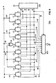
- CI denote nine conventional counters checking conditions a, b, ...i, respectively.
- Said counters when enabled, count the pulses received from block DIN.
- Enablings for the counters are obtained by the following combinations of the data present on bus 19:
- DIN separates the counting pulses received through connection 33; over wire 41 it supplies the pulses from (j-N) to (j-1), where j is the value present on bus 20 (Fig. 3) at the beginning of IND2 counting; over wire 43 pulse j; over wire 42 pulses from (j+1) to (j+N).
- pulse (j+N) DIN Upon reception of pulse (j+N) DIN supplies on wire 44 an enabling signal which performs also as a reset signal for all the counters.
- counters CA, CB When enabled, counters CA, CB count the pulses on wire 41; counters CC, CD, CE, CF, CG those on wire 42; counters CH, CI those on wire 43.
- counters CH, CI when enabled, supply it to the output on wires 52, 53 respectively.
- Counters CA,...., CG instead supply a logic "1" on the output, on wires 45, 46, 47, 48, 49, 50, 51 respectively, if they reach counting value N/2+1, i.e., half plus 1 received pulses.
- Signals on wires 45,...., 53 are applied to the inputs of register RG3 which supplies them on bus 37 when it receives the enabling signal on wire 44.
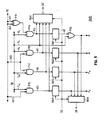
- RG4, RG5, RG6, RG7 denote four registers which, when enabled by the pulses on wire 33 (pulses relevant to the second of the consecutive countings executed by block IND2 of Fig. 3), supply to the outputs the signal applied to the inputs, connected to wires 60, 61, 62, 63, respectively.
- Register outputs carry sound-class indications, and pulses on wire 33 determine the number of intervals during which said indications are valid.
- Register RG4 supplies the indication of class Fv if and as long as the signal on wire 60 is active, which signal is supplied Yy the output of gate Pll executing the logic AND of signal F vl , coming through bus 38 from logic LGC (Fig. 3), and of signal on wire 151° belonging to bus 19.
- Register RG5 supplies the indication of class F n if and as long as the signal on wire 61 is active, which signal is supplied by the output of gate P12 which executes the logic AND of signal F n1 , coming from bus 38, and of the complement value of the signal on wire 162 coming from bus 19.
- Register RG6 supplies the indication of class A, if and as long as the signal on wire 62 is active, which signal is supplied by the output of gate P13, which executes the logic AND of signal A 1 , coming from bus 38, and of the complement value of signal on wire 162.
- Register RG7 supplies on wire 65 one of the two possible indications of plosive sound if and as long as the signal on wire 63 is active, which signal is supplied by the output of gate P14 which executes the logic AND of signal P2, coming from bus 38, and of the output of gate P10, which executes the logic EX-OR of signals on wires 161, 162 coming from bus 19.
- the signals on wires 60, ...., 63, and signal P 1 are applied to the inputs of register RG8, synchronized by the pulses on wire 33.
- RG8 emits a signal on wire 32, active when input signals are no longer active.
- the signal on wire 32 when active, stops the counter of IND2, emitting the pulses on wire 33.
- the signals of class Fv, Fn, A, P are also carried to the inputs of register RG9, which emits on wire 39 the pulses present on wire 33 when one of the indications of such classes is active.
- circuit CLSS of Fig. 3 The operation of circuit CLSS of Fig. 3 will be now described.
- time base BT At the beginning of the procedures time base BT generates signal CK with a delay of a certain number of intervals so as to allow an initial partial filling of data-word memory MEMI (Fig. 1).
- the counter of IND1 begins addressing MEM1: as long as theisilence/voice field of data words indicates silence, register RQ supplies indication Q on bus 21, to which IND1 counting pulses are also supplied through wire 30, gate P6 and wire 40, which pulses determine the number of intervals characterized by class Q. All the other circuits of CLSS remain deenergized.
- output Q of RQ activates register RSF and stops unit IND1: if spectral-stability of data word present on bus 19 indicates spectral stability threshold exceeded, the output SF will be active and will activate addressing unit IND2; otherwise output SF will be active and will activate addressing unit IND3.
- IND2 If unit IND2 is activated, then the search for sounds Fv, Fn P, A begins. IND2 inhibits IND3 through the signal on connection 31, up to the end of the search. IND2 counter addresses data words in MEM1 from position (j-N) to (j+N) where j is the address present on bus 20 upon TND2 activation; data words are supplied to circuits FPA and LGC activated by the first counting sequence supplied on connection 33. At the end of said first sequence, a combination of conditions a, ...i, decoded by LGC into one of the possible class indications supplied on bus 38, is present on output bus 37 of FPA.
- circuit DUR is energized by the second counting sequence supplied by IND2 on connection 33.
- DUR As long as DUR is active, it emits one of classes Fv, Fn, P, A on bus 21, on the basis of the analysis of the data words present on bus 19, and emits in addition on wire 39 the pulses of the second counting of IND2, which pulses determine the number of intervals identified by the relevant class, and are supplied on bus 21, through gate P6 and wire 40.
- DUR When DUR detects the end of the class found out, it stops IND2 counting by a signal on wire 32, which determines also reactivation of IND1 which begins again addressing MEM1 (Fig. 1) from the value present on bus 20 at that instant. Operation control is then taken again by register RQ as disclosed above. When output Q is active, RSF is activated again, and INDI is stopped. When output SF is active, addressing unit IND3 is activated. IND3 inhibits IND2 through connection 31 till the operation end, activates block VNS through the signal on connection 34, and addresses MEM1 starting from the address present at the activation on bus 20.
- VNS which, on the basis of their analysis,emits the indications of classes V, N, S, and of dipthong D on bus 21; VNS emits also the pause or down/up control signals for IND3 counter on connection 34 and the pulses indentifying the intervals classified V, N, S on wire 36 connected to bus 21 through gate P6 and wire 40.
- VNS When VNS detects the presence of class Q or spectral stability threshold exceeded, it stops IND3 and reactivates INDl through the signal on wire 35. Control is then taken again by unit INDl, as already described.
- active logic level on wire 3 determines the temporary stopping of time base BT and consequently of all synchronized circuits of CLSS; besides in the addressing units it causes the decrement by a unit in the counter active at that instant to take into account the shift by a position of data words in MEM1, caused by the new writing.
Landscapes
- Engineering & Computer Science (AREA)
- Computational Linguistics (AREA)
- Health & Medical Sciences (AREA)
- Audiology, Speech & Language Pathology (AREA)
- Human Computer Interaction (AREA)
- Physics & Mathematics (AREA)
- Acoustics & Sound (AREA)
- Multimedia (AREA)
- Compression, Expansion, Code Conversion, And Decoders (AREA)
- Character Discrimination (AREA)
- Management, Administration, Business Operations System, And Electronic Commerce (AREA)
- Measurement Of Mechanical Vibrations Or Ultrasonic Waves (AREA)
Applications Claiming Priority (2)
| Application Number | Priority Date | Filing Date | Title |
|---|---|---|---|
| IT6787184 | 1984-09-03 | ||
| IT67871/84A IT1179093B (it) | 1984-09-03 | 1984-09-03 | Procedimento e dispositivo per il riconoscimento senza addestramento preventivo di parole connesse appartenenti a piccoli vocabolari |
Publications (2)
| Publication Number | Publication Date |
|---|---|
| EP0173986A2 true EP0173986A2 (de) | 1986-03-12 |
| EP0173986A3 EP0173986A3 (de) | 1987-10-28 |
Family
ID=11305962
Family Applications (1)
| Application Number | Title | Priority Date | Filing Date |
|---|---|---|---|
| EP85110986A Withdrawn EP0173986A3 (de) | 1984-09-03 | 1985-08-30 | Verfahren und Vorrichtung zur Erkennung von Wortfolgen, die zu kleinen Vokabularien gehören, ohne vorausgehendes Training |
Country Status (5)
| Country | Link |
|---|---|
| EP (1) | EP0173986A3 (de) |
| JP (1) | JPS61240300A (de) |
| CA (1) | CA1230180A (de) |
| DE (1) | DE173986T1 (de) |
| IT (1) | IT1179093B (de) |
Cited By (4)
| Publication number | Priority date | Publication date | Assignee | Title |
|---|---|---|---|---|
| WO1989002146A1 (en) * | 1987-09-01 | 1989-03-09 | Reginald Alfred King | Improvements in or relating to apparatus and methods for voice recognition |
| WO2000014729A3 (en) * | 1998-09-04 | 2000-06-02 | Ericsson Telefon Ab L M | A method and a system for voice dialling |
| WO2001003114A1 (en) * | 1999-06-30 | 2001-01-11 | Glenayre Electronics, Inc. | Location and coding of unvoiced plosives in linear predictive coding of speech |
| CN113053364A (zh) * | 2019-12-27 | 2021-06-29 | 北京搜狗科技发展有限公司 | 一种语音识别方法、装置和用于语音识别的装置 |
Family Cites Families (2)
| Publication number | Priority date | Publication date | Assignee | Title |
|---|---|---|---|---|
| US3679830A (en) * | 1970-05-11 | 1972-07-25 | Malcolm R Uffelman | Cohesive zone boundary detector |
| FR2150174A5 (de) * | 1971-08-18 | 1973-03-30 | Dreyfus Jean |
-
1984
- 1984-09-03 IT IT67871/84A patent/IT1179093B/it active
-
1985
- 1985-08-30 JP JP60190059A patent/JPS61240300A/ja active Pending
- 1985-08-30 DE DE198585110986T patent/DE173986T1/de active Pending
- 1985-08-30 EP EP85110986A patent/EP0173986A3/de not_active Withdrawn
- 1985-08-30 CA CA000489833A patent/CA1230180A/en not_active Expired
Cited By (7)
| Publication number | Priority date | Publication date | Assignee | Title |
|---|---|---|---|---|
| WO1989002146A1 (en) * | 1987-09-01 | 1989-03-09 | Reginald Alfred King | Improvements in or relating to apparatus and methods for voice recognition |
| US5101434A (en) * | 1987-09-01 | 1992-03-31 | King Reginald A | Voice recognition using segmented time encoded speech |
| WO2000014729A3 (en) * | 1998-09-04 | 2000-06-02 | Ericsson Telefon Ab L M | A method and a system for voice dialling |
| US7110948B1 (en) | 1998-09-04 | 2006-09-19 | Telefonaktiebolaget Lm Ericsson (Publ) | Method and a system for voice dialling |
| WO2001003114A1 (en) * | 1999-06-30 | 2001-01-11 | Glenayre Electronics, Inc. | Location and coding of unvoiced plosives in linear predictive coding of speech |
| US6304842B1 (en) | 1999-06-30 | 2001-10-16 | Glenayre Electronics, Inc. | Location and coding of unvoiced plosives in linear predictive coding of speech |
| CN113053364A (zh) * | 2019-12-27 | 2021-06-29 | 北京搜狗科技发展有限公司 | 一种语音识别方法、装置和用于语音识别的装置 |
Also Published As
| Publication number | Publication date |
|---|---|
| EP0173986A3 (de) | 1987-10-28 |
| DE173986T1 (de) | 1988-04-07 |
| IT8467871A1 (it) | 1986-03-03 |
| IT8467871A0 (it) | 1984-09-03 |
| JPS61240300A (ja) | 1986-10-25 |
| IT1179093B (it) | 1987-09-16 |
| CA1230180A (en) | 1987-12-08 |
Similar Documents
| Publication | Publication Date | Title |
|---|---|---|
| KR100312919B1 (ko) | 화자인식을위한방법및장치 | |
| US5091948A (en) | Speaker recognition with glottal pulse-shapes | |
| Ahmadi et al. | Cepstrum-based pitch detection using a new statistical V/UV classification algorithm | |
| JP2627745B2 (ja) | 音声認識装置およびパターン認識装置 | |
| EP1309964B1 (de) | Schnelle frequenzbereichs-tonhöhenabschätzung | |
| US5390278A (en) | Phoneme based speech recognition | |
| US6292775B1 (en) | Speech processing system using format analysis | |
| US4454586A (en) | Method and apparatus for generating speech pattern templates | |
| US4087632A (en) | Speech recognition system | |
| US5459815A (en) | Speech recognition method using time-frequency masking mechanism | |
| US4032711A (en) | Speaker recognition arrangement | |
| JPS58134699A (ja) | 連続ワ−トストリング認識方法および装置 | |
| JPS6247320B2 (de) | ||
| US4370521A (en) | Endpoint detector | |
| US4937870A (en) | Speech recognition arrangement | |
| EP0118484B1 (de) | Lpc spracherkennungseinrichtung unter anwendung von energiemerkmalen | |
| USRE32172E (en) | Endpoint detector | |
| US5806031A (en) | Method and recognizer for recognizing tonal acoustic sound signals | |
| US5487129A (en) | Speech pattern matching in non-white noise | |
| US6470311B1 (en) | Method and apparatus for determining pitch synchronous frames | |
| EP0173986A2 (de) | Verfahren und Vorrichtung zur Erkennung von Wortfolgen, die zu kleinen Vokabularien gehören, ohne vorausgehendes Training | |
| JP3523382B2 (ja) | 音声認識装置及び音声認識方法 | |
| JP4199927B2 (ja) | 発声言語における少なくとも1つのキーワードを計算器により認識する方法および認識装置 | |
| Von Keller | An On‐Line Recognition System for Spoken Digits | |
| Suaudeau et al. | An efficient combination of acoustic and supra-segmental informations in a speech recognition system |
Legal Events
| Date | Code | Title | Description |
|---|---|---|---|
| PUAI | Public reference made under article 153(3) epc to a published international application that has entered the european phase |
Free format text: ORIGINAL CODE: 0009012 |
|
| AK | Designated contracting states |
Kind code of ref document: A2 Designated state(s): DE FR GB NL SE |
|
| PUAL | Search report despatched |
Free format text: ORIGINAL CODE: 0009013 |
|
| AK | Designated contracting states |
Kind code of ref document: A3 Designated state(s): DE FR GB NL SE |
|
| 17P | Request for examination filed |
Effective date: 19880112 |
|
| EL | Fr: translation of claims filed | ||
| TCNL | Nl: translation of patent claims filed | ||
| DET | De: translation of patent claims | ||
| 17Q | First examination report despatched |
Effective date: 19900129 |
|
| STAA | Information on the status of an ep patent application or granted ep patent |
Free format text: STATUS: THE APPLICATION IS DEEMED TO BE WITHDRAWN |
|
| 18D | Application deemed to be withdrawn |
Effective date: 19900609 |
|
| RIN1 | Information on inventor provided before grant (corrected) |
Inventor name: COLOMBO, MAURA Inventor name: PIRANI, GIANCORLO |