EP0174058A2 - Accélérateur du type Hall avec décharge de préionisation - Google Patents
Accélérateur du type Hall avec décharge de préionisation Download PDFInfo
- Publication number
- EP0174058A2 EP0174058A2 EP85302181A EP85302181A EP0174058A2 EP 0174058 A2 EP0174058 A2 EP 0174058A2 EP 85302181 A EP85302181 A EP 85302181A EP 85302181 A EP85302181 A EP 85302181A EP 0174058 A2 EP0174058 A2 EP 0174058A2
- Authority
- EP
- European Patent Office
- Prior art keywords
- discharge area
- hall
- anode
- preionization
- accelerator
- Prior art date
- Legal status (The legal status is an assumption and is not a legal conclusion. Google has not performed a legal analysis and makes no representation as to the accuracy of the status listed.)
- Granted
Links
- 230000005684 electric field Effects 0.000 claims abstract description 7
- 238000004891 communication Methods 0.000 claims abstract description 3
- 150000002500 ions Chemical class 0.000 claims description 29
- 238000001816 cooling Methods 0.000 claims description 15
- 239000007789 gas Substances 0.000 description 29
- 238000010884 ion-beam technique Methods 0.000 description 26
- 239000010453 quartz Substances 0.000 description 11
- VYPSYNLAJGMNEJ-UHFFFAOYSA-N silicon dioxide Inorganic materials O=[Si]=O VYPSYNLAJGMNEJ-UHFFFAOYSA-N 0.000 description 11
- 239000002826 coolant Substances 0.000 description 9
- RYGMFSIKBFXOCR-UHFFFAOYSA-N Copper Chemical compound [Cu] RYGMFSIKBFXOCR-UHFFFAOYSA-N 0.000 description 8
- 229910052802 copper Inorganic materials 0.000 description 8
- 239000010949 copper Substances 0.000 description 8
- 239000000498 cooling water Substances 0.000 description 6
- 239000004065 semiconductor Substances 0.000 description 6
- 238000009826 distribution Methods 0.000 description 5
- 230000004907 flux Effects 0.000 description 5
- 238000009413 insulation Methods 0.000 description 5
- -1 nitrogen ions Chemical class 0.000 description 5
- 238000012360 testing method Methods 0.000 description 5
- XEEYBQQBJWHFJM-UHFFFAOYSA-N Iron Chemical group [Fe] XEEYBQQBJWHFJM-UHFFFAOYSA-N 0.000 description 4
- 230000015572 biosynthetic process Effects 0.000 description 4
- 230000006872 improvement Effects 0.000 description 4
- 238000005468 ion implantation Methods 0.000 description 4
- 238000004519 manufacturing process Methods 0.000 description 4
- IJGRMHOSHXDMSA-UHFFFAOYSA-N nitrogen Substances N#N IJGRMHOSHXDMSA-UHFFFAOYSA-N 0.000 description 4
- WFKWXMTUELFFGS-UHFFFAOYSA-N tungsten Chemical compound [W] WFKWXMTUELFFGS-UHFFFAOYSA-N 0.000 description 4
- 229910052721 tungsten Inorganic materials 0.000 description 4
- 239000010937 tungsten Substances 0.000 description 4
- 229910000831 Steel Inorganic materials 0.000 description 3
- 239000007769 metal material Substances 0.000 description 3
- 229910052757 nitrogen Inorganic materials 0.000 description 3
- 230000001105 regulatory effect Effects 0.000 description 3
- 238000007789 sealing Methods 0.000 description 3
- 239000010959 steel Substances 0.000 description 3
- XLYOFNOQVPJJNP-UHFFFAOYSA-N water Substances O XLYOFNOQVPJJNP-UHFFFAOYSA-N 0.000 description 3
- 238000005299 abrasion Methods 0.000 description 2
- 238000010276 construction Methods 0.000 description 2
- 230000000694 effects Effects 0.000 description 2
- 238000002474 experimental method Methods 0.000 description 2
- 230000004927 fusion Effects 0.000 description 2
- 239000012212 insulator Substances 0.000 description 2
- 229910052751 metal Inorganic materials 0.000 description 2
- 239000002184 metal Substances 0.000 description 2
- 239000001301 oxygen Substances 0.000 description 2
- 229910052760 oxygen Inorganic materials 0.000 description 2
- BASFCYQUMIYNBI-UHFFFAOYSA-N platinum Chemical compound [Pt] BASFCYQUMIYNBI-UHFFFAOYSA-N 0.000 description 2
- 238000011160 research Methods 0.000 description 2
- UFHFLCQGNIYNRP-UHFFFAOYSA-N Hydrogen Chemical compound [H][H] UFHFLCQGNIYNRP-UHFFFAOYSA-N 0.000 description 1
- QVGXLLKOCUKJST-UHFFFAOYSA-N atomic oxygen Chemical compound [O] QVGXLLKOCUKJST-UHFFFAOYSA-N 0.000 description 1
- 229910052799 carbon Inorganic materials 0.000 description 1
- 230000001276 controlling effect Effects 0.000 description 1
- 230000007797 corrosion Effects 0.000 description 1
- 238000005260 corrosion Methods 0.000 description 1
- 238000011161 development Methods 0.000 description 1
- 230000020169 heat generation Effects 0.000 description 1
- 239000001257 hydrogen Substances 0.000 description 1
- 229910052739 hydrogen Inorganic materials 0.000 description 1
- 150000002431 hydrogen Chemical class 0.000 description 1
- 238000002513 implantation Methods 0.000 description 1
- 238000012423 maintenance Methods 0.000 description 1
- 239000000463 material Substances 0.000 description 1
- 238000002844 melting Methods 0.000 description 1
- 230000008018 melting Effects 0.000 description 1
- 150000002739 metals Chemical class 0.000 description 1
- 229910052697 platinum Inorganic materials 0.000 description 1
- 230000009467 reduction Effects 0.000 description 1
- 230000004044 response Effects 0.000 description 1
- 229910001220 stainless steel Inorganic materials 0.000 description 1
- 239000010935 stainless steel Substances 0.000 description 1
- 238000009628 steelmaking Methods 0.000 description 1
- 230000001629 suppression Effects 0.000 description 1
- 238000003786 synthesis reaction Methods 0.000 description 1
- 238000011282 treatment Methods 0.000 description 1
- 238000009423 ventilation Methods 0.000 description 1
Images







Classifications
-
- H—ELECTRICITY
- H05—ELECTRIC TECHNIQUES NOT OTHERWISE PROVIDED FOR
- H05H—PLASMA TECHNIQUE; PRODUCTION OF ACCELERATED ELECTRICALLY-CHARGED PARTICLES OR OF NEUTRONS; PRODUCTION OR ACCELERATION OF NEUTRAL MOLECULAR OR ATOMIC BEAMS
- H05H1/00—Generating plasma; Handling plasma
- H05H1/54—Plasma accelerators
-
- H—ELECTRICITY
- H01—ELECTRIC ELEMENTS
- H01J—ELECTRIC DISCHARGE TUBES OR DISCHARGE LAMPS
- H01J27/00—Ion beam tubes
- H01J27/02—Ion sources; Ion guns
- H01J27/08—Ion sources; Ion guns using arc discharge
- H01J27/14—Other arc discharge ion sources using an applied magnetic field
- H01J27/143—Hall-effect ion sources with closed electron drift
-
- H—ELECTRICITY
- H01—ELECTRIC ELEMENTS
- H01J—ELECTRIC DISCHARGE TUBES OR DISCHARGE LAMPS
- H01J37/00—Discharge tubes with provision for introducing objects or material to be exposed to the discharge, e.g. for the purpose of examination or processing thereof
- H01J37/02—Details
- H01J37/04—Arrangements of electrodes and associated parts for generating or controlling the discharge, e.g. electron-optical arrangement or ion-optical arrangement
- H01J37/08—Ion sources; Ion guns
Definitions
- This invention relates to a Hall accelerator having a discharge area with anode and cathode means and an electromagnet producing a magnetic field therein, which accelerator causes gas discharge therein when a gas is injected thereto so as to generate, accelerate and emit Hall ions therefrom. More particularly, the invention relates to a Hall accelerator with preionization discharge, which accelerator has a magnetron type anode means adapted to produce an auxiliary discharge thereat.
- the Hall accelerator is an effective source of beam ions for ion implanting operations in semiconductor device production and in the improvement of metallic material properties.
- the ever increasing demand for semiconductor devices is expected to continue in the future.
- there are various limitations in the Hall ion beam produced by Hall accelerators of the prior art namely, a comparatively small maximum current of up to one kA, a low voltage in the order of several hundreds of volts, and a comparatively wide divergence angle of about 30 degrees in case of short pulses in the order of several milliseconds.
- Fig. 10 illustrates a Hall accelerator of the prior art.
- a discharge area with an annular cross section is defined between concentric cylindrical insulating walls IW, which discharge area is provided with a disk-shaped anode A mounted on one end thereof and a cathode C mounted on the opposite end thereof.
- the cathode C has a large circular opening aligned with the anode A.
- Iron cores F in the form of shell type with a solenoid S wound on its central leg are disposed in contact with the insulating walls IW in such a manner that a radial magnetic field is produced in the annular cross-sectional space of the discharge area.
- a suitable gas is directly introduced into the discharge area through a gas valve GV, so as to cause gas discharge therein for emitting ions.
- the Hall accelerator of such simple arrangement has a shortcoming in that, due to the heat generation at the electrodes the ion emission is restricted to be 6f low voltage and short pulse duration even if a large current is possible, and a
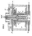
- Fig. 11 In the figure, two concentric quartz walls Q, i.e., an inner cylindrical wall and an outer tubular wall, define an elongated discharge area with an annular cross section. An annular tungsten anode TA and an annular copper cathode CC are disposed at opposite ends of the discharge area in a manner similar to that of Fig. 10. A long shell type iron core F carrying a first stage solenoid S 1 and a second stage solenoid S 2 is in contact with the quartz walls Q in such a manner that a radial magnetic field is generated in the discharge area. Thereby, the Hall accelerator of Fig. 11 emits a continuous Hall ion beam with a maximum voltage of up to 30 kV and a maximum current of up to 1.5 A for several seconds.
- Fig. 11 cools the electromagnet with cooling oil and the copper cathode CC with cooling water by using coolant inlets WI and coolant outlets WO.
- the anode TA in the discharge area is, however, simply made of tungsten having a high melting point but not cooled.
- any continuous operation for a long period of time will be difficult, because the annular anode has only a small surface area and it will be heavily bombarded by high- density electrons generated by gas discharge in the discharge area.
- the Hall accelerators of the prior art have a shortcoming in that long continuous operation is difficult due to the lack of anode cooling and that water cooling for the anode at a high voltage poses a structural difficulty from the standpoint of electric insulation.
- an object of the invention is to obviate the above-mentioned shortcomings of the prior art by providing an improved Hall accelerator with preionization discharge.
- the Hall accelerator according to the invention can continuously emit a Hall ion beam with a high voltage of 10-100 kV and a medium current of 1-10 A at a small beam divergence angle by continuous operation without using any filaments.
- the Hall accelerator of the invention has a number of outstanding features: namely, that it emits the Hall ion beam in a stable manner with a high reproducibility and a high gas efficiency; that it can accelerate Hall ions of various elements either individually or in combination; and that it can control the energy distribution in the ion beam over a wide range.
- Another object of the invention is to provide a practicable Hall accelerator with preionization discharge capable of demonstrating the above features, which accelerator is suitable for various applications as listed below: namely,
- a main discharge area with an annular cross section is formed between concentric quartz walls Q 1 and Q 2 .
- An anode means and a cathode means are mounted on opposite ends of the discharge area.
- the anode means includes concentric cylindrical electrodes coaxial with the main discharge area, an anode terminal means adapted to apply a voltage across the concentric electrodes to generate an electric field therebetween, and an auxiliary electromagnet surrounding the concentric electrodes so as to generate a magnetic field in a longitudinal axial direction of the concentric electrodes, so that the anode means forms a magnetron type preionization discharge area in communication with the main discharge area.
- the cathode means includes an inner semispherical electrode aligned with the main discharge area, and an annular electrode surrounding the semispherical electrode with a spacing therefrom and extending away from the anode means more than the semispherical electrode.
- a gas inlet opening is provided so as to introduce a gas into the preionization discharge area.
- An electromagnet surrounds the main discharge area so as to generate a radial magnetic field therein. Whereby, the gas from the preionization discharge area is ionized into Hall ions and accelerated in the main discharge area.
- forced cooling systems are provided in those portions which are subjected to heat loading during continuous operation, such as the cylindrical electrodes of the anode means and the semispherical and annular electrodes of the cathode means.
- a means for reversing electric current in the auxiliary electromagnet may be provided in the anode means.
- A is an anode
- TA is a tungsten anode
- AA l and AA 2 are coaxial anode electrodes
- C is a cathode
- CC is a copper cathode
- AC 1 and AC 2 are coaxial cathode electrodes
- DA is a main discharge area
- MA is a magnetoron type preionization discharge area
- CA is an inner cathode- holding rod
- F is an iron core
- S, S 1 , S2 are solenoids of electromagnets
- IW is an insulating wall
- IP is an insulating support post
- Q is a quartz wall
- M is a MAKOR insulator
- GV is a gas valve
- GI is a gas inlet
- WI is a coolant inlet
- WO is a coolant outlet
- B r is a radial magnetic field
- B m is an axial magnetic field
- IO 1 through 10 3 are terminals
- Fig. 1 shows a schematic sectional view of an embodiment of the Hall accelerator with preionization discharge according to the invention
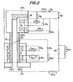
- Fig. 2 shows the electric circuit of the Hall accelerator.
- the Hall accelerator of the invention shown in Fig. 1 is somewhat similar to the conventional accelerator shown in Fig. 11; namely, a main discharge area with an annular or elliptic cross section is defined between concentric quartz walls Q 1 and Q 2 , and an anode means AA and a cathode means AC are mounted on opposite ends of the main discharge area DA.
- An elongated shell type iron core F carries a pair of first-stage solenoids S 1 separately wound thereon is coupled to the main discharge area DA in such a manner that a radial magnetic field B is generated in the main discharge area DA.
- a suitable gas is introduced into the main discharge area through a gas inlet GI, and the gas discharge takes place therein continuously.
- suitable coolant such as water or oil
- suitable coolant is delivered to individual electrodes and electromagnets through corresponding coolant inlets WI 1 -WI 5 .
- the coolant is removed from the accelerator through corresponding coolant outlets WO 1 -WO 5 .
- the Hall accelerator of Fig. 1 is clearly different from the conventional Hall accelerator shown in Fig. 11 at the following points.
- the anode of the conventional Hall acceleator of Fig. 11 is formed by simply disposing an annular tungsten anode TA in the main discharge area.
- the anode means is formed by a pair of cylindrical electrodes AA 1 and AA 2 made of oxygen-free copper and disposed coaxially on the opposing surfaces of the inner and outer quartz walls Q 1 and Q 2 so as to face each other across the main discharge area.
- a voltage V M of for instance several hundred V is applied across the inner electrode AA 1 and the outer electrode AA 2 of the anode means from a power source B 2 so as to cause an auxiliary discharge current I M to flow therethrough.
- the Hall accelerator of the invention uses a pair of second-stage or auxiliary electromagnet solenoids 8 2 in the form of Helmholtz coil surrounding the coaxial electrodes AA 1 and AA 2 , so that an axial magnetic field B m of for instance several hundred Gauss is generated in the axial direction of the main discharge area.
- an axial magnetic field B m of for instance several hundred Gauss is generated in the axial direction of the main discharge area.
- the space between inner and outer cylindrical electrodes AA 1 and AA 2 is referred to as a magnetron type preionization discharge area MA. It is an important feature of the invention that, apart from the discharge in the main discharge area DA, an auxiliary discharge takes place in the magnetron type preionization discharge area MA, and the gas discharge in the main discharge area DA is stabilized by such auxiliary discharge.
- the axial magnetic field B produced by the second-stage or auxiliary electromagnet solenoids S 2 laterally traverses a MAKOR insulator M which seals the top end of the magnetron type preionization discharge area MA, while the radial field B r produced in the intermediate area between the first-stage solenoid S 1 and the second-stage solenoids S 2 laterally traverses the quartz walls Q 1 and Q 2 surrounding the discharge area.
- the insulating members at the upper and lower ends of the magnetron type preionization discharge area MA are lateraly traversed by the magnetic field and electrified with negative charge. Accordingly, electrons generated by the auxiliary discharge in the magnetron type preionization discharge area MA are effectively confined in the area neighboring the anode means thanks to the combination of the magnetron like magnetic field orientation and the negative charge at the top and bottom ends thereof.
- magnetron type preionization discharge area electrons confined therein ensure effective auxiliary discharge of gas injected therein, such as hydrogen gas (H 2 ), and the main discharge is highly stabilized. Consequently, Hall ions can be emitted with a high reproducibility from the Hall accelerator of the invention.
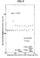
- main discharge accelerating current (Iacc) vs. magnetron type electric field voltage (V M ) characteristics can be produced as shown in Fig. 4.
- the main discharge accelerating current also acts as an accelerating current of the Hall ion beam.
- the Hall ion beam accelerating characteristics can be controlled in a number of different ways as shown in Fig. 5, by regulating in combination the polarity and the magnitude of the exciting current for the axial magnetic field B m of the magnetron type preionization discharge area, and the magnitude of the exciting current for the radial magnetic field B r .
- the generation of the auxiliary discharge in the magnetron type preionization discharge area MA can be controlled in a stable manner with a good reproducibility by regulating in combination the magnetic field being applied, the electric field being applied, and the gas inflow.
- that surface area of the anode means where electrons collide can be made considerably larger than that of the conventional Hall accelerator, so that continuous operation of the Hall accelerator is greatly facilitated.
- the inventors actually made a test model of the Hall accelerator according to the invention and carried out a series of experiments on the test model.
- the experiments proved that the generation of the auxiliary discharge in the magnetron type preionization discharge area MA resulted in a high gas efficiency and ensured stable generation of Hall ion beams with a high reproducibility.
- the test model demonstrated that its output was not restricted to Hall ion beams of one kind element, such as hydrogen (H 2 ) ions, but Hall ions of different kinds could be mixed together, accelerated and emitted by the test model.
- the Hall accelerator of the invention considerably improves the convergence of the Hall ion beams.
- the Hall accelerator of the invention shown in Fig. 1 uses a more sophisticated cathode formation, namely a concentric combination of a semispherical inner copper cathode electrode AC 1 and an annular outer copper cathode electrode AC 2 , the outer electrode AC 2 extending in the ion beam emitting direction slightly more than the inner electrode AC 1 .
- the electric potentials of the inner and outer cathode electrodes AC 1 and AC 2 are kept the same as shown in Fig.
- the test model also demonstrated excellent efficiency; namely, the output efficiency n in terms of the ratio of the extracted power to the input power was 46%, which represented a remarkable improvement over the prior art due to the use of the magnetron type preionization discharge area MA.
- the Hall accelerator of the invention succeeded in considerably improving the beam divergence angle from the conventional level of some 30 degrees to about 6 degrees as shown in Fig. 7. This significant reduction of the beam divergence angle appears to be due to the combined use of the magnetoron type preionization discharge area MA and the above-mentioned coaxial formation of the cathode means with electrodes AC 1 and AC 2 .
- the Hall accelerator of the invention as shown in Fig. 1 uses forced water or oil cooling systems at all the portions where heat load is applied; namely, the coaxial anode electrodes AA 1 and AA 2 , the concentric cathode electrodes AC 1 and AC 2 , and first-stage and second-stage electromagnet solenoids S 1 and S 2 .
- the magnetron type electric and magnetic fields must be maintained.
- the inside surface of the inner cylindrical anode electrode AA 1 held at a high potential must be cooled by cooling water at the ground potential.
- the cylindrical anode electrode AA 1 has an inner cathode-electrode-holding rod CA of the ground potential extending therethrough, so that the semispherical inner cathode electrode AC 1 is held in alignment with the inner cylindrical anode electrode AA 1 .
- the emission of the Hall ion beam from the cathode opening requires the inner cathode-electrode-holding rod CA to be of cantilever structure. Accordingly, the fixed end of the rod CA must be used for pouring in and draining out the cooling water for cooling both the anode electrode AA 1 at a high potential and the inner cathode electrode AC 1 at the ground potential.
- the cooling water must descend and ascend through the narrow gap between the cylindrical inner anode electrode AA 1 and the inner cathode-electrode-supporting rod CA while performing three functions; namely, cooling the inner surface of the anode electrode AA 1 , maintaining the electric insulation between the anode electrode AA 1 at a high potential and the rod CA at the ground potential, and providing the vacuum sealing.
- the inner cathode-electrode-holding rod CA of the embodiment of Fig. 1 has a double-pipe construction, and the cooling water for the inner cathode electrode AC 1 is fed through the innermost tube and guided to pour out to the outer tube at the inner cathode electrode AC 1 .
- a three-layer cylindrical water-cooling channel is provided, and double spiral grooves are formed in each layer of the water-cooling channel.
- BAITON 0 rings are disposed at suitable intervals so as to ensure both the electric insulation and the vacuum sealing.
- the cooling water descends and ascends along the double spiral grooves.
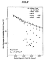
- the main discharge accelerating current (I acc ) vs. the radial magnetic field (B ) characteristics as shown in Fig. 8 and the main discharge accelerating current (I acc ) vs. the main discharge accelerating voltage (V acc ) ) characteristics as shown in Fig. 9 can be achieved by controlling in combination the axial magnetic field B in the magnetron like preionization discharge area MA, the voltage V N across the inner and outer cylindrical anode electrodes AA 1 and AA 2 , and the radial magnetic field B r in the main discharge area DA.
- the duration of the ion beam emission in the Hall accelerator of the invention is controlled, for instance, by electronically regulating a gas inlet valve disposed at the gas inlet GI of Fig. 1, which gas inlet valve has a gas passage gap whose magnitude is electronically controllable by a piezo-electric element.
- the ion beam can be accurately controlled with .an excellent reproducibility, so as to emit the desired amount of ions for a desired period of time, by suitably selecting parameters of the electronically controllable gas valve.
- the range of stable operation of the Hall accelerator of the invention is remarkably expanded by the use of the auxiliary discharge at the magnetron type preionization discharge area MA in the proximity of the anode means.
- the Hall accelerator of the invention can produce a mixed Hall ion beam at a high gas efficiency, which mixed Hall ion beam simultaneously contains differet kinds of ions. Since no filament is used, the Hall accelerator can emit oxygen ion beams at a high speed at least from the theoretical point of view.
- a Hall accelerator according to the present invention has at least three major structural improvements over the prior art: namely, that a magnetron type preionization discharge area is provided in the proximity of an anode means; that a cathode means is formed of a coaxial combination of an inner semispherical electrode and an outer annular electrode, the outer electrode extending toward ion emitting direction more than the inner electrode so as to cause a recess toward the inner electrode in electric field at the ion emitting end of the accelerator; and that forced cooling systems are provided in all those portions which are subjected to heat loading during continuous operation, while ensuring electric insulation and the vacuum sealing.
- the Hall accelerator according to the invention has a comparatively simple structure and yet can continuously emit high-energy ion beams at a high efficiency, which ion beams have considerably improved properties over the prior art. Further, since no filaments are used, maintenance work is hardly necessary. Therefore, the Hall accelerator of the invention suits best the purpose of providing ion sources for ion implanting operations in a very wide variety of industrial fields.
Landscapes
- Chemical & Material Sciences (AREA)
- Engineering & Computer Science (AREA)
- Combustion & Propulsion (AREA)
- Physics & Mathematics (AREA)
- Plasma & Fusion (AREA)
- Spectroscopy & Molecular Physics (AREA)
- Analytical Chemistry (AREA)
- Particle Accelerators (AREA)
- Electron Sources, Ion Sources (AREA)
Applications Claiming Priority (2)
| Application Number | Priority Date | Filing Date | Title |
|---|---|---|---|
| JP182463/84 | 1984-08-31 | ||
| JP59182463A JPS6161345A (ja) | 1984-08-31 | 1984-08-31 | マグネトロン補助放電付ホ−ルアクセラレ−タ |
Publications (3)
| Publication Number | Publication Date |
|---|---|
| EP0174058A2 true EP0174058A2 (fr) | 1986-03-12 |
| EP0174058A3 EP0174058A3 (en) | 1987-09-30 |
| EP0174058B1 EP0174058B1 (fr) | 1990-01-03 |
Family
ID=16118702
Family Applications (1)
| Application Number | Title | Priority Date | Filing Date |
|---|---|---|---|
| EP85302181A Expired - Lifetime EP0174058B1 (fr) | 1984-08-31 | 1985-03-28 | Accélérateur du type Hall avec décharge de préionisation |
Country Status (4)
| Country | Link |
|---|---|
| US (1) | US4703222A (fr) |
| EP (1) | EP0174058B1 (fr) |
| JP (1) | JPS6161345A (fr) |
| DE (1) | DE3575237D1 (fr) |
Cited By (4)
| Publication number | Priority date | Publication date | Assignee | Title |
|---|---|---|---|---|
| EP0265365A1 (fr) * | 1986-10-20 | 1988-04-27 | Harold R. Kaufman | Source d'ions de type end-hall |
| US4922342A (en) * | 1987-03-24 | 1990-05-01 | U.S. Philips Corporation | System of transmitting high-definition television pictures via a narrow-passband channel |
| US4935813A (en) * | 1987-03-24 | 1990-06-19 | U.S. Philips Corporation | System of transmitting high-definition television pictures via a relatively narrow passband channel, and also a transmitter and a receiver suitable for the system |
| CN102123558A (zh) * | 2010-12-22 | 2011-07-13 | 武汉天和技术股份有限公司 | 长寿命内空式阴极双压缩等离子体发生装置 |
Families Citing this family (14)
| Publication number | Priority date | Publication date | Assignee | Title |
|---|---|---|---|---|
| US5029259A (en) * | 1988-08-04 | 1991-07-02 | Mitsubishi Denki Kabushiki Kaisha | Microwave electron gun |
| US5455081A (en) * | 1990-09-25 | 1995-10-03 | Nippon Steel Corporation | Process for coating diamond-like carbon film and coated thin strip |
| JPH04152719A (ja) * | 1990-10-16 | 1992-05-26 | Fujitsu Ltd | 音声検出回路 |
| RU2092983C1 (ru) * | 1996-04-01 | 1997-10-10 | Исследовательский центр им.М.В.Келдыша | Плазменный ускоритель |
| US6086962A (en) * | 1997-07-25 | 2000-07-11 | Diamonex, Incorporated | Method for deposition of diamond-like carbon and silicon-doped diamond-like carbon coatings from a hall-current ion source |
| RU2139647C1 (ru) * | 1998-06-18 | 1999-10-10 | Бугрова Антонина Ивановна | Плазменный ускоритель с замкнутым дрейфом электронов |
| AUPP479298A0 (en) * | 1998-07-21 | 1998-08-13 | Sainty, Wayne | Ion source |
| RU2162624C1 (ru) * | 1999-05-26 | 2001-01-27 | Байдаков Сергей Георгиевич | Способ ускорения ионов и устройство для его реализации |
| AU2002232395A1 (en) * | 2000-11-03 | 2002-05-15 | Tokyo Electron Limited | Hall effect ion source at high current density |
| US6735935B2 (en) * | 2000-12-14 | 2004-05-18 | Busek Company | Pulsed hall thruster system |
| US6805779B2 (en) * | 2003-03-21 | 2004-10-19 | Zond, Inc. | Plasma generation using multi-step ionization |
| US6806651B1 (en) | 2003-04-22 | 2004-10-19 | Zond, Inc. | High-density plasma source |
| US6903511B2 (en) * | 2003-05-06 | 2005-06-07 | Zond, Inc. | Generation of uniformly-distributed plasma |
| RU2251090C1 (ru) * | 2003-09-01 | 2005-04-27 | Федеральное государственное унитарное предприятие "Опытное конструкторское бюро "Факел" | Способ прогнозирования изменения параметров стационарного плазменного двигателя в процессе выработки ресурса |
Family Cites Families (3)
| Publication number | Priority date | Publication date | Assignee | Title |
|---|---|---|---|---|
| GB1365672A (en) * | 1971-10-21 | 1974-09-04 | Atomic Energy Authority Uk | Hall current accelerators |
| US4179351A (en) * | 1976-09-09 | 1979-12-18 | Hewlett-Packard Company | Cylindrical magnetron sputtering source |
| US4122347A (en) * | 1977-03-21 | 1978-10-24 | Georgy Alexandrovich Kovalsky | Ion source |
-
1984
- 1984-08-31 JP JP59182463A patent/JPS6161345A/ja active Granted
-
1985
- 1985-03-26 US US06/716,368 patent/US4703222A/en not_active Expired - Lifetime
- 1985-03-28 DE DE8585302181T patent/DE3575237D1/de not_active Expired - Lifetime
- 1985-03-28 EP EP85302181A patent/EP0174058B1/fr not_active Expired - Lifetime
Cited By (5)
| Publication number | Priority date | Publication date | Assignee | Title |
|---|---|---|---|---|
| EP0265365A1 (fr) * | 1986-10-20 | 1988-04-27 | Harold R. Kaufman | Source d'ions de type end-hall |
| US4862032A (en) * | 1986-10-20 | 1989-08-29 | Kaufman Harold R | End-Hall ion source |
| US4922342A (en) * | 1987-03-24 | 1990-05-01 | U.S. Philips Corporation | System of transmitting high-definition television pictures via a narrow-passband channel |
| US4935813A (en) * | 1987-03-24 | 1990-06-19 | U.S. Philips Corporation | System of transmitting high-definition television pictures via a relatively narrow passband channel, and also a transmitter and a receiver suitable for the system |
| CN102123558A (zh) * | 2010-12-22 | 2011-07-13 | 武汉天和技术股份有限公司 | 长寿命内空式阴极双压缩等离子体发生装置 |
Also Published As
| Publication number | Publication date |
|---|---|
| EP0174058A3 (en) | 1987-09-30 |
| US4703222A (en) | 1987-10-27 |
| JPH02814B2 (fr) | 1990-01-09 |
| EP0174058B1 (fr) | 1990-01-03 |
| JPS6161345A (ja) | 1986-03-29 |
| DE3575237D1 (de) | 1990-02-08 |
Similar Documents
| Publication | Publication Date | Title |
|---|---|---|
| US4703222A (en) | Hall accelerator with preionization discharge | |
| EP0184812B1 (fr) | Générateur de plasma à haute fréquence | |
| US5019752A (en) | Plasma switch with chrome, perturbated cold cathode | |
| EP0283519B1 (fr) | Generateur ionique, installation de formation de films minces utilisant ce generateur et source d'ions | |
| US6346768B1 (en) | Low energy ion gun having multiple multi-aperture electrode grids with specific spacing requirements | |
| US5557172A (en) | Plasma beam generating method and apparatus which can generate a high-power plasma beam | |
| Osipov et al. | A plasma–cathode electron source designed for industrial use | |
| US3315125A (en) | High-power ion and electron sources in cascade arrangement | |
| KR100307070B1 (ko) | 고속원자빔공급원 | |
| JPH08306329A (ja) | 高磁束密度イオン源 | |
| JPS5740845A (en) | Ion beam generator | |
| Smith Jr et al. | Penning surface‐plasma source scaling laws—theory and practice | |
| Mathias et al. | On the performance of high perveance electron guns | |
| CN118888423B (zh) | 一种磁约束的直流辉光放电等离子体装置和键合设备 | |
| JPH0696680A (ja) | 金属イオン源 | |
| JP3213135B2 (ja) | 高速原子線源 | |
| SU854198A1 (ru) | Ионна пушка | |
| JPH01197950A (ja) | ホローカソード型イオン源 | |
| JP2909696B2 (ja) | ビーム発生方法及び装置 | |
| SU1145383A1 (ru) | Источник ионов | |
| Tanaka et al. | Reduction of gas flow into a hollow cathode ion source for a neutral beam injector | |
| US3327148A (en) | Mirror-type electron gun | |
| JPH04181636A (ja) | 金属イオン源 | |
| CN119852151A (zh) | 多电荷态离子源及多电荷态离子束输出调控方法 | |
| Cole | Improvements in and relating to hall current accelerators |
Legal Events
| Date | Code | Title | Description |
|---|---|---|---|
| PUAI | Public reference made under article 153(3) epc to a published international application that has entered the european phase |
Free format text: ORIGINAL CODE: 0009012 |
|
| AK | Designated contracting states |
Kind code of ref document: A2 Designated state(s): DE FR GB |
|
| 17P | Request for examination filed |
Effective date: 19860730 |
|
| PUAL | Search report despatched |
Free format text: ORIGINAL CODE: 0009013 |
|
| AK | Designated contracting states |
Kind code of ref document: A3 Designated state(s): DE FR GB |
|
| 17Q | First examination report despatched |
Effective date: 19890213 |
|
| GRAA | (expected) grant |
Free format text: ORIGINAL CODE: 0009210 |
|
| AK | Designated contracting states |
Kind code of ref document: B1 Designated state(s): DE FR GB |
|
| REF | Corresponds to: |
Ref document number: 3575237 Country of ref document: DE Date of ref document: 19900208 |
|
| ET | Fr: translation filed | ||
| PLBE | No opposition filed within time limit |
Free format text: ORIGINAL CODE: 0009261 |
|
| STAA | Information on the status of an ep patent application or granted ep patent |
Free format text: STATUS: NO OPPOSITION FILED WITHIN TIME LIMIT |
|
| 26N | No opposition filed | ||
| REG | Reference to a national code |
Ref country code: GB Ref legal event code: IF02 |
|
| PGFP | Annual fee paid to national office [announced via postgrant information from national office to epo] |
Ref country code: FR Payment date: 20040309 Year of fee payment: 20 |
|
| PGFP | Annual fee paid to national office [announced via postgrant information from national office to epo] |
Ref country code: GB Payment date: 20040324 Year of fee payment: 20 |
|
| PGFP | Annual fee paid to national office [announced via postgrant information from national office to epo] |
Ref country code: DE Payment date: 20040408 Year of fee payment: 20 |
|
| PG25 | Lapsed in a contracting state [announced via postgrant information from national office to epo] |
Ref country code: GB Free format text: LAPSE BECAUSE OF EXPIRATION OF PROTECTION Effective date: 20050327 |
|
| REG | Reference to a national code |
Ref country code: GB Ref legal event code: PE20 |