EP0174172B1 - Montage de panneau de recouvrement - Google Patents
Montage de panneau de recouvrement Download PDFInfo
- Publication number
- EP0174172B1 EP0174172B1 EP19850306205 EP85306205A EP0174172B1 EP 0174172 B1 EP0174172 B1 EP 0174172B1 EP 19850306205 EP19850306205 EP 19850306205 EP 85306205 A EP85306205 A EP 85306205A EP 0174172 B1 EP0174172 B1 EP 0174172B1
- Authority
- EP
- European Patent Office
- Prior art keywords
- frame
- panel
- assembly according
- access panel
- rods
- Prior art date
- Legal status (The legal status is an assumption and is not a legal conclusion. Google has not performed a legal analysis and makes no representation as to the accuracy of the status listed.)
- Expired
Links
- 238000007789 sealing Methods 0.000 claims description 7
- 229920001084 poly(chloroprene) Polymers 0.000 claims description 2
- 238000010348 incorporation Methods 0.000 description 1
- 239000007769 metal material Substances 0.000 description 1
- 230000002093 peripheral effect Effects 0.000 description 1
Images
Classifications
-
- E—FIXED CONSTRUCTIONS
- E04—BUILDING
- E04B—GENERAL BUILDING CONSTRUCTIONS; WALLS, e.g. PARTITIONS; ROOFS; FLOORS; CEILINGS; INSULATION OR OTHER PROTECTION OF BUILDINGS
- E04B9/00—Ceilings; Construction of ceilings, e.g. false ceilings; Ceiling construction with regard to insulation
- E04B9/003—Ceilings; Construction of ceilings, e.g. false ceilings; Ceiling construction with regard to insulation with movable parts, e.g. pivoting panels, access doors
Definitions
- This invention relates to an access panel assembly primarily for a suspended ceiling.
- An access panel assembly is known from G.B. publication 2116601 which discloses a suspended ceiling access panel pivotally mounted in a frame by means of a fixed pin extending outwardly from each of a pair of side walls of the panel. The pins engage in an L-shaped slot in a respective side wall of the frame arranged to allow the panel to be removed from the frame.
- An object of the present invention is to provide an improved access panel assembly the design of which allows at least one, and preferably both, of these disadvantages to be overcome.
- an access panel assembly comprising a frame, and an access panel pivotally mounted in the frame by hinge means which, during opening and closing of the panel, permit angular movement and translation of said panel in the plane of the frame, characterised thereby that, during opening and closing, said hinge means permit translation of the panel away from or towards respectively, the pivot axis, in the plane of the panel.
- said translation permits the panel to clear the frame.
- the hinge means comprise two rods pivotally mounted on the frame and received by one or more brackets secured to the access panel.
- the rods may be 'T' shaped and engage with respective 'T' shaped slots in the frame so that, by appropriate manipulation whereby the heads of the rods pass through the slots, the access panel may be removed from the frame.
- the hinge axis may move inwardly of the frame as the panel is opened in use.
- the frame may incorporate a circumferential seal to co-operate with the access panel.
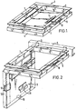
- an access panel assembly 1 comprises a frame 2 and an access panel 3.
- the frame 2 has side walls of a stepped configuration, as shown, such that a lower flange 4 has an outer surface which determines the outer dimensions of the assembly and an inner surface which defines the access panel 3 seating.
- the frame 2 is either bolted on to a primary channel 5 by means of brackets 6 as shown in phantom lines or, alternatively, can be suspended by rigid rod hangers (not shown).
- One side wall 7 of the frame 2 is provided with a pair of T-slots 8 for releasably receiving the hinge mounting of the access panel 3 as will be explained in detail below, whilst an opposed side wall 9 has a lock 10 disposed within its step and adjacent a longitudinal slot (not shown). The lock moved by a locking key so that the tongue protrudes through the slot in the frame 2 and engages under a lock bracket 11 on the access panel 3 thereby locking the panel 3 to the frame 2.
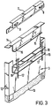
- the access panel 3 has depending side flanges 12, of a depth consistent with a ceiling tile 13 to be positioned within the panel 3 in conventional manner, and a removable end wall 14 which allows positioning of the tile 13.
- the end wall 14 has spaced screw holes 15 which enable the end wall 14 to be secured to a U-shaped bracket 16 welded to the upper surface of the access panel 3.
- the bracket 16 has an aligned pair of holes at each end each of which receive a T-shaped hinge rod 17.
- the hinge rods 17 are slidable relative to the bracket 16 within limits determined by a stop 18 positioned on each of the rods 17 and between the spaced upstanding limbs of U-shaped bracket 16.
- the heads of the hinge rods 17, which define a movable hinge axis, are dimensioned such that they are able to pass through the slots 8 in the frame 2.
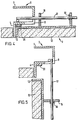
- the hinge rods 17 are positioned within the slots 8 so that, in the closed position of the access panel 3 with the locking tongue in engagement with bracket 11 as shown in Figures 1 and 4, the hinge rods 17 extend horizontally with the stops 18 in abutment with the inside surface of the farther of the limbs of bracket 16.
- the lock 10 is released by manipulation of a lock key through guide 19. This allows the access panel 3 to hinge about the hinge axis made possible by the provision of the slots 8 with the rods 17 passing into the horizontally extending portions of the respective slots 8.
- the access panel 3 Simultaneously, as the access panel 3 starts to open, it drops downwardly along the rods 17 until the stops 18 abut the inside surface of the nearer of the limbs of the bracket 16 and the head of the rods 17, defining the hinge axis, moves towards the slots 8 as seen from Figures 4 and 5.
- the access panel 8 moves radially of the hinge axis as well as angularly to drop clear of the lower flange 4 of the frame 2 so that it can be opened fully into the position shown in Figure 2.
- the access panel 3 is held and lifted slightly until the heads of the rods 17 are aligned with the heads of the respective slots 8. Then the access panel 3 can be moved away from the side wall 7 to release the access panel 3 from the frame 2.
- an important advantage of the present invention is that it allows the incorporation of air sealing.
- This sealing is provided by means of a peripheral sealing gasket 20 positioned on the inside of the step of frame 2 as shown in Figures 4 and 5. Because the access panel 3 drops away from its hinge points on release, the sealing is effected by simple pressure of the access panel 3 against the gasket 20 without rubbing movement of the panel across the gasket 20 which would otherwise be the case.
- the access panel assembly 1 is suitably made of metal material and the sealing gasket 20 may be neoprene.
Landscapes
- Engineering & Computer Science (AREA)
- Architecture (AREA)
- Physics & Mathematics (AREA)
- Electromagnetism (AREA)
- Civil Engineering (AREA)
- Structural Engineering (AREA)
- Specific Sealing Or Ventilating Devices For Doors And Windows (AREA)
Claims (9)
Applications Claiming Priority (2)
| Application Number | Priority Date | Filing Date | Title |
|---|---|---|---|
| GB8422186 | 1984-09-03 | ||
| GB848422186A GB8422186D0 (en) | 1984-09-03 | 1984-09-03 | Access panel assembly |
Publications (3)
| Publication Number | Publication Date |
|---|---|
| EP0174172A2 EP0174172A2 (fr) | 1986-03-12 |
| EP0174172A3 EP0174172A3 (en) | 1987-04-15 |
| EP0174172B1 true EP0174172B1 (fr) | 1989-05-24 |
Family
ID=10566171
Family Applications (1)
| Application Number | Title | Priority Date | Filing Date |
|---|---|---|---|
| EP19850306205 Expired EP0174172B1 (fr) | 1984-09-03 | 1985-09-02 | Montage de panneau de recouvrement |
Country Status (3)
| Country | Link |
|---|---|
| EP (1) | EP0174172B1 (fr) |
| DE (1) | DE3570478D1 (fr) |
| GB (1) | GB8422186D0 (fr) |
Families Citing this family (2)
| Publication number | Priority date | Publication date | Assignee | Title |
|---|---|---|---|---|
| GB9105838D0 (en) * | 1991-03-19 | 1991-05-01 | Exitile Ltd | Demountable door |
| US6581345B2 (en) * | 2000-04-03 | 2003-06-24 | Modernfold, Inc. | Track concealing system for operable walls |
Family Cites Families (4)
| Publication number | Priority date | Publication date | Assignee | Title |
|---|---|---|---|---|
| DE1967866U (de) * | 1967-04-29 | 1967-09-07 | Gruenzweig & Hartmann | Bauelementesatz zum herstellen einer unterdecke. |
| US4115955A (en) * | 1977-08-01 | 1978-09-26 | Aldrich Darrell L | Panel and hinge assembly |
| GB2035428B (en) * | 1977-11-16 | 1982-09-08 | Littlewood T | Trap door assembly |
| GB2116601B (en) * | 1982-03-16 | 1985-10-09 | Universal Panels Limited | Suspended ceiling access panel |
-
1984
- 1984-09-03 GB GB848422186A patent/GB8422186D0/en active Pending
-
1985
- 1985-09-02 DE DE8585306205T patent/DE3570478D1/de not_active Expired
- 1985-09-02 EP EP19850306205 patent/EP0174172B1/fr not_active Expired
Also Published As
| Publication number | Publication date |
|---|---|
| DE3570478D1 (en) | 1989-06-29 |
| EP0174172A3 (en) | 1987-04-15 |
| EP0174172A2 (fr) | 1986-03-12 |
| GB8422186D0 (en) | 1984-10-10 |
Similar Documents
| Publication | Publication Date | Title |
|---|---|---|
| US4541595A (en) | Removable interior window unit for aircraft | |
| US4852213A (en) | Releasable extruded hinge | |
| US4416088A (en) | Motor-vehicle side door | |
| AU4159096A (en) | Variable volume test chamber | |
| CA2218473A1 (fr) | Structure d'obturation d'une porte paliere | |
| GB2180297A (en) | Door buffer | |
| ES289804U (es) | Recipiente provisto de medios para obturar y abrir el inte- rior del mismo | |
| CA2258710A1 (fr) | Glace pouvant etre revitree | |
| CA2013102A1 (fr) | Ferme-porte pour porte coulissante | |
| GB2116601A (en) | Suspended ceiling access panel | |
| EP0174172B1 (fr) | Montage de panneau de recouvrement | |
| EP0160543A3 (fr) | Aérateur pouvant être fermé pour empêcher la diffusion de fumée et de feu | |
| CA1137137A (fr) | Toit ouvrant pour vehicules | |
| US4290792A (en) | Filter construction | |
| US4289349A (en) | Sunroof | |
| GB2085721A (en) | Bath-tub with a door for motor handicapped | |
| US3748465A (en) | Luminaire closure device | |
| JPS63503471A (ja) | 窓用両位置自動施錠装置 | |
| US4790107A (en) | Window securing device | |
| US2360554A (en) | Porthole cover assembly | |
| GB2132308A (en) | Access hatch | |
| US3370745A (en) | Explosion relief wall | |
| GB2033465A (en) | Hinged panels | |
| US5450844A (en) | Locking device for the container of a gas mask and breathing equipment | |
| JPS5755283A (en) | Ramp for ship |
Legal Events
| Date | Code | Title | Description |
|---|---|---|---|
| PUAI | Public reference made under article 153(3) epc to a published international application that has entered the european phase |
Free format text: ORIGINAL CODE: 0009012 |
|
| AK | Designated contracting states |
Kind code of ref document: A2 Designated state(s): BE DE FR GB NL SE |
|
| PUAL | Search report despatched |
Free format text: ORIGINAL CODE: 0009013 |
|
| AK | Designated contracting states |
Kind code of ref document: A3 Designated state(s): BE DE FR GB NL SE |
|
| 17P | Request for examination filed |
Effective date: 19871014 |
|
| 17Q | First examination report despatched |
Effective date: 19880505 |
|
| GRAA | (expected) grant |
Free format text: ORIGINAL CODE: 0009210 |
|
| AK | Designated contracting states |
Kind code of ref document: B1 Designated state(s): BE DE FR GB NL SE |
|
| PG25 | Lapsed in a contracting state [announced via postgrant information from national office to epo] |
Ref country code: SE Effective date: 19890524 Ref country code: NL Effective date: 19890524 Ref country code: BE Effective date: 19890524 |
|
| REF | Corresponds to: |
Ref document number: 3570478 Country of ref document: DE Date of ref document: 19890629 |
|
| ET | Fr: translation filed | ||
| NLV1 | Nl: lapsed or annulled due to failure to fulfill the requirements of art. 29p and 29m of the patents act | ||
| PLBE | No opposition filed within time limit |
Free format text: ORIGINAL CODE: 0009261 |
|
| STAA | Information on the status of an ep patent application or granted ep patent |
Free format text: STATUS: NO OPPOSITION FILED WITHIN TIME LIMIT |
|
| 26N | No opposition filed | ||
| PGFP | Annual fee paid to national office [announced via postgrant information from national office to epo] |
Ref country code: FR Payment date: 19910930 Year of fee payment: 7 |
|
| PGFP | Annual fee paid to national office [announced via postgrant information from national office to epo] |
Ref country code: DE Payment date: 19911001 Year of fee payment: 7 |
|
| PG25 | Lapsed in a contracting state [announced via postgrant information from national office to epo] |
Ref country code: FR Effective date: 19930528 |
|
| PG25 | Lapsed in a contracting state [announced via postgrant information from national office to epo] |
Ref country code: DE Effective date: 19930602 |
|
| REG | Reference to a national code |
Ref country code: GB Ref legal event code: 737A |
|
| REG | Reference to a national code |
Ref country code: FR Ref legal event code: ST |
|
| PGFP | Annual fee paid to national office [announced via postgrant information from national office to epo] |
Ref country code: GB Payment date: 19930827 Year of fee payment: 9 |
|
| PG25 | Lapsed in a contracting state [announced via postgrant information from national office to epo] |
Ref country code: GB Effective date: 19940902 |
|
| GBPC | Gb: european patent ceased through non-payment of renewal fee |
Effective date: 19940902 |