EP0174208A1 - Manipulateurs - Google Patents
Manipulateurs Download PDFInfo
- Publication number
- EP0174208A1 EP0174208A1 EP85306357A EP85306357A EP0174208A1 EP 0174208 A1 EP0174208 A1 EP 0174208A1 EP 85306357 A EP85306357 A EP 85306357A EP 85306357 A EP85306357 A EP 85306357A EP 0174208 A1 EP0174208 A1 EP 0174208A1
- Authority
- EP
- European Patent Office
- Prior art keywords
- axis
- rotate
- manipulator
- mirror
- drive means
- Prior art date
- Legal status (The legal status is an assumption and is not a legal conclusion. Google has not performed a legal analysis and makes no representation as to the accuracy of the status listed.)
- Granted
Links
Images
Classifications
-
- B—PERFORMING OPERATIONS; TRANSPORTING
- B23—MACHINE TOOLS; METAL-WORKING NOT OTHERWISE PROVIDED FOR
- B23K—SOLDERING OR UNSOLDERING; WELDING; CLADDING OR PLATING BY SOLDERING OR WELDING; CUTTING BY APPLYING HEAT LOCALLY, e.g. FLAME CUTTING; WORKING BY LASER BEAM
- B23K26/00—Working by laser beam, e.g. welding, cutting or boring
- B23K26/08—Devices involving relative movement between laser beam and workpiece
- B23K26/0869—Devices involving movement of the laser head in at least one axial direction
- B23K26/0876—Devices involving movement of the laser head in at least one axial direction in at least two axial directions
- B23K26/0884—Devices involving movement of the laser head in at least one axial direction in at least two axial directions in at least three axial directions, e.g. manipulators, robots
-
- B—PERFORMING OPERATIONS; TRANSPORTING
- B23—MACHINE TOOLS; METAL-WORKING NOT OTHERWISE PROVIDED FOR
- B23K—SOLDERING OR UNSOLDERING; WELDING; CLADDING OR PLATING BY SOLDERING OR WELDING; CUTTING BY APPLYING HEAT LOCALLY, e.g. FLAME CUTTING; WORKING BY LASER BEAM
- B23K26/00—Working by laser beam, e.g. welding, cutting or boring
- B23K26/08—Devices involving relative movement between laser beam and workpiece
- B23K26/10—Devices involving relative movement between laser beam and workpiece using a fixed support, i.e. involving moving the laser beam
-
- B—PERFORMING OPERATIONS; TRANSPORTING
- B25—HAND TOOLS; PORTABLE POWER-DRIVEN TOOLS; MANIPULATORS
- B25J—MANIPULATORS; CHAMBERS PROVIDED WITH MANIPULATION DEVICES
- B25J17/00—Joints
- B25J17/02—Wrist joints
- B25J17/0283—Three-dimensional joints
- B25J17/0291—Three-dimensional joints having axes crossing at an oblique angle, i.e. other than 90 degrees
-
- B—PERFORMING OPERATIONS; TRANSPORTING
- B25—HAND TOOLS; PORTABLE POWER-DRIVEN TOOLS; MANIPULATORS
- B25J—MANIPULATORS; CHAMBERS PROVIDED WITH MANIPULATION DEVICES
- B25J19/00—Accessories fitted to manipulators, e.g. for monitoring, for viewing; Safety devices combined with or specially adapted for use in connection with manipulators
- B25J19/0025—Means for supplying energy to the end effector
- B25J19/0029—Means for supplying energy to the end effector arranged within the different robot elements
- B25J19/0037—Means for supplying energy to the end effector arranged within the different robot elements comprising a light beam pathway, e.g. laser
Definitions
- the present invention relates to manipulators and is concerned with that type of manipulator which comprises a first member which is mounted to rotate about a first axis and carries a second member which is mounted to rotate about a second axis obliquely inclined to the first axis, the second member carrying a third member which is mounted to rotate about a third axis obliquely inclined to the second axis, the first, second and third axes preferably passing through a single point.
- a manipulator of this general type is disclosed in British Patent No. 1565730 and is commonly referred to as a coincident three axis manipulator or wrist.
- the third member which may be termed an end effector, may carry a tool or the like and by effecting selective rotation about one or more of the axes of rotation the tool carried by the end effector may be brought into any desired position and orientation.
- Such manipulators are thus particularly suitable for use in remote handling apparatus or robots.
- a tool may be moved by such a manipulator, either alone or at the same time as a tool.
- it may be desirable either to heat treat or to weld a work piece using a laser beam during an operation which includes the use of a tool carried by a manipulator of the type referred to above.
- the tool may be brought to the required position by virtue of the various axes of rotation provided within the manipulator and it is an object of the present invention to provide such a manipulator in which a beam of electromagnetic radiation, such as a laser beam, may be transmitted through such a manipulator and directed to any desired position regardless of the relative orientations of the various relatively moveable members.
- a manipulator of the type referred to above includes first and second mirrors carried by the first member and mounted to rotate therewith, the first mirror being situated on the first axis and positioned to reflect a beam of electromagnetic radiation which is substantially parallel to the first axis onto the second mirror which is situated on the second axis, and third and fourth mirrors carried by the second member and mounted to rotate therewith, the third mirror being situated on the second axis and positioned to reflect the beam of radiation reflected from the second mirror onto the fourth mirror, and the fourth mirror being situated on the third axis and positioned to direct the beam of radiation substantially parallel to the third axis.
- the beam of radiation enters parallel to and preferably coincident with the first axis and always leaves the manipulator parallel to and preferably coincident with the third axis regardless of the relative angular positions of the various members.
- the third member or or end effector may carry additional optical elements, for instance a mirror on which the beam of radiation is incident and which is inclined to the third axis.
- it may carry a tool thereby permitting the work piece on which the tool has performed or is about to perform an operation to be heat treated or to be welded, though in the latter case one or more focussing lenses or mirrors will additionally be required to focus the beam of radiation down to the required area.
- first and second mirrors are connected to a common carrier which is releasably carried by the first member.
- the third and fourth mirrors are also connected to a common carrier which is releasably carried by the second member.
- the manipulator may, of course, include additional optical elements for the purpose of conducting the beam of radiation through it, it is preferred that it includes only four mirrors and that these are associated in pairs and rigidly connected to two common carriers whereby all the mirrors may be removed from the manipulator for cleaning or replacement only by removing the two carriers.
- the various members of the manipulator may be moved to the required relative angular positions manually. It is, however, preferred that the manipulator includes drive means arranged to rotate at least one of the first, second and third members about its respective axis.
- the drive means may take one of many known forms of appropriate drive means but in the preferred embodiment the manipulator includes a rotationally fixed base member carrying the first member and first annular drive means disposed around the first axis and between the base member and the first member to rotate the first member.
- the first drive means is preferably accommodated within a substantially enclosed space defined by the base member and the first member.
- the manipulator preferably also includes second annular drive means disposed around the second axis and between the first and second members to rotate the second member and/or third annular drive means disposed around the third axis and between the second and third members to rotate the third member.
- the drive means is preferably accommodated in a substantially enclosed space defined by the two members to which it is arranged to impart relative rotation.
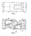
- the manipulator comprises a rotationally fixed base member 2 which carries a first member 4 which in turn carries a second member 6 which in turn carries a third member or end effector 8.
- the base member 2 and the first member 4 together define a cylindrical space which accommodates an annual drive means and gearing which is designated 10.
- the drive means and gearing 10 connect the members 2 and 4 and is arranged to rotate the member 4 with respect to the member 2 about an axis 12.
- the second member 6 is connected to the first member 4 by a further annular drive means and gearing 14 which is accommodated in a cylindrical space enclosed by the first and second members and which is arranged to rotate the second member 6 with respect to the first member 4 about a second axis 16 which is obliquely inclined to the first axis by about 120°.
- the third member 8 is connected to the second member 6 by a third annular drive means and gearing 18 which is accommodated in a cylindrical space defined by the second and third members and is arranged to rotate the third member 8 about a third axis 20 with respect to the second member.
- the drive means 10, 14 and 18 are of generally conventional construction and are thus not described in detail and are illustrated only diagrammatically.
- a common carrier or cassette 24 Connected to the first member 4 by a plurality of screws 22 is a common carrier or cassette 24 to which a first mirror 26 and a second mirror 28 are rigidly connected.
- the first mirror is situated on the first axis 12 and positioned to reflect a beam of radiation coincident with the axis 12 onto the second mirror 28 which is positioned on the second axis 16.
- the second member 6 carries a removeable carrier or cassette 30 to which a third mirror 32 and a fourth mirror 34 are rigidly connected.
- the third mirror 32 is positioned so that the beam of radiation reflected from the second mirror 28 is incident on it and then reflected onto the fourth mirror 34 which in turn is so positioned that the beam of radiation incident on it is reflected in a direction which is parallel to and preferably coincident with the third axis 20.
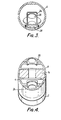
- the various members 2, 4, 6 and 8 and the cassettes 24 and 30 are provided with appropriate holes whereby a beam of radiation whose axis is coincident with the first axis 12 is incident on the first mirror and then reflected to the second, third and fourth mirror and then leaves the manipulator along the third axis.
- a beam of radiation may be directed in any desired direction and, more importantly, may be directed and optionally focussed onto a work piece on which a tool which may be carried by the end effector has performed or will perform an operation.
- various drive means are electrically activated and controlled and it will be appreciated that each of them may be controlled by manual signals.
- the drive means are connected to a common logic unit, ie. a computer, which is appropriately programmed so that the beam of radiation may be automatically directed to any number of desired locations in a desired sequence.
- the construction of the present invention enables a laser beam to be transmitted through a coincident three axis wrist in a manner which enables the mirrors, of which only four are required, to be rigidly mounted to respective portions of the wrist without the need for providing for compensating angular movement of each mirror.
- the construction of the present invention is, thus, both simple and inexpensive to manufacture.
Landscapes
- Engineering & Computer Science (AREA)
- Physics & Mathematics (AREA)
- Optics & Photonics (AREA)
- Mechanical Engineering (AREA)
- Robotics (AREA)
- Plasma & Fusion (AREA)
- Laser Beam Processing (AREA)
- Manipulator (AREA)
- Electrically Driven Valve-Operating Means (AREA)
- Crystals, And After-Treatments Of Crystals (AREA)
- Laser Surgery Devices (AREA)
- Mounting And Adjusting Of Optical Elements (AREA)
Priority Applications (1)
| Application Number | Priority Date | Filing Date | Title |
|---|---|---|---|
| AT85306357T ATE35235T1 (de) | 1984-09-07 | 1985-09-06 | Manipulator. |
Applications Claiming Priority (2)
| Application Number | Priority Date | Filing Date | Title |
|---|---|---|---|
| GB8422663 | 1984-09-07 | ||
| GB08422663A GB2164017B (en) | 1984-09-07 | 1984-09-07 | Manipulator with laser beam mirrors |
Publications (2)
| Publication Number | Publication Date |
|---|---|
| EP0174208A1 true EP0174208A1 (fr) | 1986-03-12 |
| EP0174208B1 EP0174208B1 (fr) | 1988-06-22 |
Family
ID=10566414
Family Applications (1)
| Application Number | Title | Priority Date | Filing Date |
|---|---|---|---|
| EP85306357A Expired EP0174208B1 (fr) | 1984-09-07 | 1985-09-06 | Manipulateurs |
Country Status (7)
| Country | Link |
|---|---|
| US (1) | US4659192A (fr) |
| EP (1) | EP0174208B1 (fr) |
| JP (1) | JPS6172215A (fr) |
| AT (1) | ATE35235T1 (fr) |
| DE (1) | DE3563424D1 (fr) |
| GB (1) | GB2164017B (fr) |
| NO (1) | NO160980C (fr) |
Cited By (5)
| Publication number | Priority date | Publication date | Assignee | Title |
|---|---|---|---|---|
| EP0238309A3 (en) * | 1986-03-17 | 1987-12-02 | Cincinnati Milacron Inc. | Wrist and forearm assembly for a robot |
| EP0238307A3 (en) * | 1986-03-17 | 1988-05-04 | Cincinnati Milacron Inc. | Robot wrist and forearm assembly and wrist assembly for an industrial robot |
| EP0238308A3 (en) * | 1986-03-17 | 1988-05-18 | Cincinnati Milacron Inc. | Laser robot |
| EP0299551A1 (fr) * | 1987-07-10 | 1989-01-18 | Bruno Bisiach | Robot industriel multiarticulé à plusieurs degrés de liberté |
| CN1065886C (zh) * | 1992-06-30 | 2001-05-16 | 埃克森化学专利公司 | 燃料油组合物、用于其中的添加剂组合物及其应用 |
Families Citing this family (5)
| Publication number | Priority date | Publication date | Assignee | Title |
|---|---|---|---|---|
| EP0242438A1 (fr) * | 1986-04-17 | 1987-10-28 | Cincinnati Milacron Inc. | Manipulateur et machine robotique utilisant un manipulateur |
| US4886348A (en) * | 1988-10-26 | 1989-12-12 | Westinghouse Electric Corp. | Total transmissibility optical system |
| US5044738A (en) * | 1989-12-11 | 1991-09-03 | Consulier Engineering, Inc. | Wide angle viewing system |
| DE10261530A1 (de) * | 2002-12-23 | 2004-07-22 | Gerhard Wanger | Optisches Element zur Anbringung an einer Welle |
| CN103552088B (zh) * | 2013-10-12 | 2016-06-22 | 杨兆奎 | 一种机械腕 |
Citations (5)
| Publication number | Priority date | Publication date | Assignee | Title |
|---|---|---|---|---|
| US3390274A (en) * | 1964-12-07 | 1968-06-25 | White Avionics Corp | Rotating light conductor for instrument reading |
| DE3148562A1 (de) * | 1980-12-19 | 1982-08-19 | ASEA AB, 72183 Västerås | "anordnung zur uebertragung von messsignalen zwischen einem rotierenden teil und einem nichtrotierenden teil" |
| US4402234A (en) * | 1981-08-13 | 1983-09-06 | General Motors Corporation | Three-axis wrist mechanism |
| DE3207698A1 (de) * | 1982-03-04 | 1983-09-08 | Robert Bosch Gmbh, 7000 Stuttgart | Industrieroboter mit einer einrichtung zur erhoehung der arbeitsgenauigkeit |
| DE3440930A1 (de) * | 1983-11-10 | 1985-05-30 | American Telephone And Telegraph Co., New York, N.Y. | Robotersystem zur fuehrung von elektromagnetischen wellen |
Family Cites Families (7)
| Publication number | Priority date | Publication date | Assignee | Title |
|---|---|---|---|---|
| GB502561A (en) * | 1936-06-18 | 1939-03-20 | Augusto Baroni | Universal panoramic telescope |
| DE1130196B (de) * | 1960-11-22 | 1962-05-24 | Gerhard Hopp Dr Ing | Fernrohr |
| FR82946E (fr) * | 1962-05-15 | 1964-05-08 | Guide d'onde articulé pour ondes électromagnétiques submillimétriques ou optiques | |
| GB1494082A (en) * | 1974-02-20 | 1977-12-07 | Secr Social Service Brit | Viewing devices |
| DE2754614C2 (de) * | 1977-12-08 | 1984-02-23 | Storz, Karl, 7200 Tuttlingen | Vorrichtung zur Übertragung endoskopischer Bilder mit gelenkig miteinander verbundenen Gliedern |
| GB2120202A (en) * | 1982-05-03 | 1983-11-30 | Nova Robotics Inc | Industrial robot |
| US4539462A (en) * | 1983-01-24 | 1985-09-03 | Westinghouse Electric Corp. | Robotic laser beam delivery apparatus |
-
1984
- 1984-09-07 GB GB08422663A patent/GB2164017B/en not_active Expired
-
1985
- 1985-09-06 NO NO853505A patent/NO160980C/no unknown
- 1985-09-06 JP JP60197482A patent/JPS6172215A/ja active Pending
- 1985-09-06 EP EP85306357A patent/EP0174208B1/fr not_active Expired
- 1985-09-06 AT AT85306357T patent/ATE35235T1/de not_active IP Right Cessation
- 1985-09-06 DE DE8585306357T patent/DE3563424D1/de not_active Expired
- 1985-09-09 US US06/773,687 patent/US4659192A/en not_active Expired - Fee Related
Patent Citations (5)
| Publication number | Priority date | Publication date | Assignee | Title |
|---|---|---|---|---|
| US3390274A (en) * | 1964-12-07 | 1968-06-25 | White Avionics Corp | Rotating light conductor for instrument reading |
| DE3148562A1 (de) * | 1980-12-19 | 1982-08-19 | ASEA AB, 72183 Västerås | "anordnung zur uebertragung von messsignalen zwischen einem rotierenden teil und einem nichtrotierenden teil" |
| US4402234A (en) * | 1981-08-13 | 1983-09-06 | General Motors Corporation | Three-axis wrist mechanism |
| DE3207698A1 (de) * | 1982-03-04 | 1983-09-08 | Robert Bosch Gmbh, 7000 Stuttgart | Industrieroboter mit einer einrichtung zur erhoehung der arbeitsgenauigkeit |
| DE3440930A1 (de) * | 1983-11-10 | 1985-05-30 | American Telephone And Telegraph Co., New York, N.Y. | Robotersystem zur fuehrung von elektromagnetischen wellen |
Cited By (5)
| Publication number | Priority date | Publication date | Assignee | Title |
|---|---|---|---|---|
| EP0238309A3 (en) * | 1986-03-17 | 1987-12-02 | Cincinnati Milacron Inc. | Wrist and forearm assembly for a robot |
| EP0238307A3 (en) * | 1986-03-17 | 1988-05-04 | Cincinnati Milacron Inc. | Robot wrist and forearm assembly and wrist assembly for an industrial robot |
| EP0238308A3 (en) * | 1986-03-17 | 1988-05-18 | Cincinnati Milacron Inc. | Laser robot |
| EP0299551A1 (fr) * | 1987-07-10 | 1989-01-18 | Bruno Bisiach | Robot industriel multiarticulé à plusieurs degrés de liberté |
| CN1065886C (zh) * | 1992-06-30 | 2001-05-16 | 埃克森化学专利公司 | 燃料油组合物、用于其中的添加剂组合物及其应用 |
Also Published As
| Publication number | Publication date |
|---|---|
| US4659192A (en) | 1987-04-21 |
| NO853505L (no) | 1986-03-10 |
| DE3563424D1 (en) | 1988-07-28 |
| GB8422663D0 (en) | 1984-10-10 |
| EP0174208B1 (fr) | 1988-06-22 |
| JPS6172215A (ja) | 1986-04-14 |
| NO160980C (no) | 1989-06-21 |
| ATE35235T1 (de) | 1988-07-15 |
| NO160980B (no) | 1989-03-13 |
| GB2164017A (en) | 1986-03-12 |
| GB2164017B (en) | 1987-09-03 |
Similar Documents
| Publication | Publication Date | Title |
|---|---|---|
| US4578554A (en) | Laser welding apparatus | |
| US4638143A (en) | Robot-laser system | |
| CA1256508A (fr) | Robot industriel de soudage et de decoupage au rayon laser | |
| EP0174208B1 (fr) | Manipulateurs | |
| US4626999A (en) | Apparatus for controlled manipulation of laser focus point | |
| US4623229A (en) | Articulated laser arm | |
| US4710606A (en) | Two-axis optic wrist for laser applications | |
| JPH0380596B2 (fr) | ||
| EP0199590A2 (fr) | Système robot à laser | |
| JPS59134682A (ja) | マニピュレ−タ装置 | |
| US4650952A (en) | Robot-laser system | |
| US4892992A (en) | Industrial laser robot system | |
| JPH0460798B2 (fr) | ||
| EP0296776A3 (fr) | Aiguille chirurgicale et méthode et appareillage pour sa fabrication | |
| US4661681A (en) | Robotic marking machine | |
| JPS62176787A (ja) | 加工位置検出装置 | |
| JPS59133987A (ja) | レ−ザ材料加工装置 | |
| JPH01210189A (ja) | レーザー・ビーム発射装置用整合用具 | |
| EP0421135A3 (en) | Method and process for determining the position and diameter of a laser beam focus, used for workpieces machining with a high power laser | |
| US20230118887A1 (en) | Scanning radial laser processing with bi-conical reflection | |
| JPH0782154B2 (ja) | レーザービーム等の平行ビームを配送するための装置 | |
| WO1991004828A1 (fr) | Decoupeuse a rayon laser multi-axe et haute puissance avec moniteur de traitement d'image | |
| JPS6043237B2 (ja) | レ−ザ加工装置 | |
| USRE34597E (en) | Robot-laser system | |
| JP2665232B2 (ja) | 5軸制御機械のティーチング装置 |
Legal Events
| Date | Code | Title | Description |
|---|---|---|---|
| PUAI | Public reference made under article 153(3) epc to a published international application that has entered the european phase |
Free format text: ORIGINAL CODE: 0009012 |
|
| AK | Designated contracting states |
Kind code of ref document: A1 Designated state(s): AT BE CH DE FR GB IT LI LU NL SE |
|
| 17P | Request for examination filed |
Effective date: 19860910 |
|
| RAP1 | Party data changed (applicant data changed or rights of an application transferred) |
Owner name: INTEGRATED LASER SYSTEMS LIMITED |
|
| 17Q | First examination report despatched |
Effective date: 19871103 |
|
| GRAA | (expected) grant |
Free format text: ORIGINAL CODE: 0009210 |
|
| AK | Designated contracting states |
Kind code of ref document: B1 Designated state(s): AT BE CH DE FR IT LI LU NL SE |
|
| REF | Corresponds to: |
Ref document number: 35235 Country of ref document: AT Date of ref document: 19880715 Kind code of ref document: T |
|
| ITF | It: translation for a ep patent filed | ||
| REF | Corresponds to: |
Ref document number: 3563424 Country of ref document: DE Date of ref document: 19880728 |
|
| ET | Fr: translation filed | ||
| PLBE | No opposition filed within time limit |
Free format text: ORIGINAL CODE: 0009261 |
|
| STAA | Information on the status of an ep patent application or granted ep patent |
Free format text: STATUS: NO OPPOSITION FILED WITHIN TIME LIMIT |
|
| 26N | No opposition filed | ||
| PGFP | Annual fee paid to national office [announced via postgrant information from national office to epo] |
Ref country code: NL Payment date: 19900930 Year of fee payment: 6 |
|
| PGFP | Annual fee paid to national office [announced via postgrant information from national office to epo] |
Ref country code: FR Payment date: 19910215 Year of fee payment: 6 |
|
| PGFP | Annual fee paid to national office [announced via postgrant information from national office to epo] |
Ref country code: DE Payment date: 19910218 Year of fee payment: 6 Ref country code: BE Payment date: 19910218 Year of fee payment: 6 |
|
| PGFP | Annual fee paid to national office [announced via postgrant information from national office to epo] |
Ref country code: CH Payment date: 19910221 Year of fee payment: 6 |
|
| PGFP | Annual fee paid to national office [announced via postgrant information from national office to epo] |
Ref country code: SE Payment date: 19910222 Year of fee payment: 6 |
|
| PGFP | Annual fee paid to national office [announced via postgrant information from national office to epo] |
Ref country code: AT Payment date: 19910225 Year of fee payment: 6 |
|
| PGFP | Annual fee paid to national office [announced via postgrant information from national office to epo] |
Ref country code: LU Payment date: 19910314 Year of fee payment: 6 |
|
| EPTA | Lu: last paid annual fee | ||
| PG25 | Lapsed in a contracting state [announced via postgrant information from national office to epo] |
Ref country code: LU Free format text: LAPSE BECAUSE OF NON-PAYMENT OF DUE FEES Effective date: 19910906 Ref country code: AT Effective date: 19910906 |
|
| PG25 | Lapsed in a contracting state [announced via postgrant information from national office to epo] |
Ref country code: SE Effective date: 19910907 |
|
| ITTA | It: last paid annual fee | ||
| PG25 | Lapsed in a contracting state [announced via postgrant information from national office to epo] |
Ref country code: LI Effective date: 19910930 Ref country code: CH Effective date: 19910930 Ref country code: BE Effective date: 19910930 |
|
| BERE | Be: lapsed |
Owner name: INTEGRATED LASER SYSTEMS LTD Effective date: 19910930 |
|
| PG25 | Lapsed in a contracting state [announced via postgrant information from national office to epo] |
Ref country code: NL Effective date: 19920401 |
|
| NLV4 | Nl: lapsed or anulled due to non-payment of the annual fee | ||
| PG25 | Lapsed in a contracting state [announced via postgrant information from national office to epo] |
Ref country code: FR Effective date: 19920529 |
|
| REG | Reference to a national code |
Ref country code: CH Ref legal event code: PL |
|
| PG25 | Lapsed in a contracting state [announced via postgrant information from national office to epo] |
Ref country code: DE Effective date: 19920602 |
|
| REG | Reference to a national code |
Ref country code: FR Ref legal event code: ST |
|
| EUG | Se: european patent has lapsed |
Ref document number: 85306357.6 Effective date: 19920408 |