EP0174276A1 - Outil de serrage à moteur - Google Patents
Outil de serrage à moteur Download PDFInfo
- Publication number
- EP0174276A1 EP0174276A1 EP85810389A EP85810389A EP0174276A1 EP 0174276 A1 EP0174276 A1 EP 0174276A1 EP 85810389 A EP85810389 A EP 85810389A EP 85810389 A EP85810389 A EP 85810389A EP 0174276 A1 EP0174276 A1 EP 0174276A1
- Authority
- EP
- European Patent Office
- Prior art keywords
- coupling part
- counter
- screwing device
- toothing
- torque
- Prior art date
- Legal status (The legal status is an assumption and is not a legal conclusion. Google has not performed a legal analysis and makes no representation as to the accuracy of the status listed.)
- Withdrawn
Links
Images

Classifications
-
- B—PERFORMING OPERATIONS; TRANSPORTING
- B25—HAND TOOLS; PORTABLE POWER-DRIVEN TOOLS; MANIPULATORS
- B25B—TOOLS OR BENCH DEVICES NOT OTHERWISE PROVIDED FOR, FOR FASTENING, CONNECTING, DISENGAGING, OR HOLDING
- B25B23/00—Details of, or accessories for, spanners, wrenches, screwdrivers
- B25B23/14—Arrangement of torque limiters or torque indicators in wrenches or screwdrivers
- B25B23/141—Mechanical overload release couplings
Definitions
- the invention relates to a motor-driven screwing device with a torque limiting clutch arranged between a drive unit and a drive spindle for the tool, which has a coupling part which is connected in a rotationally fixed manner to the drive spindle and which is in clutch engagement with a driven part of the drive unit under the force of a spring element.
- Such known torque limiting clutches have spherical coupling parts which sit in the drive pockets associated with the drive spindle and protrude spring-loaded into locking recesses in an output part of the drive unit.
- the coupling parts for transmitting the torque are supported on the flanks of the locking recesses, the flank facing in the screwing-in direction of rotation serving to transmit the screwing-in torque while the opposite flank absorbs the torque when turning back.
- the screwing-in process is ended by responding to the torque limiting clutch.
- the screw is tightened with the highest possible torque.
- a higher counter-torque is required compared to this screw-in torque.
- torque limiting clutch such a higher torque cannot be achieved due to the symmetrical design of the locking recesses, so that loosening or unscrewing of the screws is not possible.
- the structure of these torque limiting clutches is complex and prone to failure.
- the locking recesses for the spherical coupling parts are asymmetrical in longitudinal section.
- this device is not intended for unscrewing screws.
- the flank of the locking recesses facing the screw-in direction of rotation is at 90 ° to the end face of the driven part, which has the consequence that if the screw is turned back, there would be no disengagement and this would result in an unacceptable safety risk for the operator.
- the invention has for its object to provide a screwdriver that allows a reliable, not associated with a security risk unscrewing screws and is characterized by a simple structure.
- the object is achieved in that the driven part has end teeth facing the coupling part and the coupling part for coupling engagement with the driven part has counter teeth, the teeth having inclined flanks such that the pitch angle of the counter teeth of the coupling part in the screwing-in direction is smaller than the pitch angle of the counter teeth of the coupling part is designed against the screw-in direction of rotation.
- the flank with a larger pitch angle ensures safe uncoupling by disengaging the counter-toothing of the preferably disc-shaped coupling part.
- Optimal response moments for both the screwing-in process and for unscrewing are preferably achieved in that the smaller pitch angle is 20 to 40 °, preferably 25 to 35 °, and the larger pitch angle is 42 to 55 °, preferably 45 to 52 °.
- the teeth are designed as straight radial teeth.
- the toothings advantageously have the same height over their entire end face. This creates a large, mutually acting surface for the teeth.
- the optimal time for the response of the torque limiting clutch is ensured according to a further proposal of the invention in that the height of the toothings is 3 to 7%, preferably 5%, of the outer diameter of the toothings.
- uniform force distribution over the entire tooth width and thus reduced wear is achieved in that the thickness of the teeth increases away from the center of the toothing.
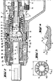
- the screwing device has a device housing, generally designated 1, with a handle 2 projecting sideways from it.
- the power supply line is provided by a cable 3 opening into the handle 2.
- the screwdriver is switched on or off via a trigger 4.
- An actuating sleeve 5 is connected to the front of the device housing 1 and to this a depth stop designated overall by 6. This is axially exceeded by the working end of a screw insert 7.
- Figure 2 shows the stub of the drive shaft 8 of an engine.
- An output part in the form of a gear 9 meshes with the end-side pinion 8a of the drive shaft 8 and is rotatably supported by a rotary bearing 11 on an axially subdivided drive spindle, generally designated 12.
- Gear 9 shouldered by a roller bearing 13.
- the gear 9 has a spur toothing 9a.
- the drive spindle 12 is secured against rotation by a spline toothing 14, a disc-shaped coupling part 15 is slidably assigned. This has a corresponding counter toothing 15a.
- the counter toothing 15a of the coupling part 15 is held in engagement with the end toothing 9a of the toothed wheel 9 by the force of a spring element which is formed by plate springs and is designated overall by 16.
- the spring element 16 is supported by a further roller bearing 17 and a locking ring 18, which is stuck in a stop bush 19, from the front.
- the gear 9, the coupling part 15 and the spring element 16 together form a torque limiting clutch, designated overall by 21.
- the rotary bearing of the rear section 22 of the drive spindle 12 is used by a ball bearing 23 which is axially immovably fixed on the section 22 between a support ring 24 and a shoulder 22a.
- the stop bushing 19 is connected by a thread 25 to the device housing 1 by a sliding connection.
- the stop bush 19 In a radial bore 19a, the stop bush 19 carries a locking ball 26, which snaps into place in a longitudinal groove 28 distributed over the inner surface of the device housing 1 by a compression spring 27. A rotation of the stop bush 19 can therefore only take place by overcoming this locking.
- a scale ring 29 is pressed onto the stop bush 19.
- a reading window 31 in the device housing 1 enables reading of the respectively set torque level.
- the maximum and minimum setting of the torque is limited by a pin 32 seated in the stop bushing 19.
- a rotary bearing 33 is provided for the front section 34 of the drive spindle 12. Furthermore, a sealing ring 35 is located in front of the rotary bearing 33.
- a connecting ring 37 which is part of the depth stop 6, is in screw connection with the stop bush 19 via a further thread 36.
- the actuating sleeve 5 which is made of plastic, carries a connecting element 38, which is firmly connected to it, in the form of a cast-in bolt.
- the forward end region 38a of the connecting element 38 projects into an axial bore 37a of the connecting ring 37.
- the opposite rear free end region 38b of the connecting element 38 engages in latching openings 19b of the stop bush 19, a plurality of which are arranged on a circular path on the end face.
- the actuating sleeve 5 In this engagement position of the connecting element 38, the actuating sleeve 5 is held in a circumferential groove 19c of the stop bush 19 by the latching engagement of a bead 5a arranged on resilient fingers.
- the torque introduced by the drive shaft 8 is transmitted 80 to the drive spindle 12 via the torque limiting clutch 21 and from there to the screw insert 7.
- the torque that can be transmitted by the torque limiting clutch 21 is set by changing the axial position of the stop bushing 19. For this purpose, this must be rotated, which is accomplished with the aid of the actuating sleeve 5.
- a manual rotation of the actuating sleeve 5 causes due to the engagement of the connecting element 38 in one of the locking openings gen 19b rotationally driving the stop sleeve 19. This is axially offset via the thread 25.
- an axial displacement of the connecting ring 37 is required.
- the actuating sleeve 5 is pulled up to a stop ring 41 held in the stop bush 19 until it comes to rest.
- the bead 5a is pretensioned on a support flank 19d facing the front of the stop sleeve 19.
- a movement of the actuating sleeve 5 into the functional position shown in FIG. 2 is therefore only possible after the support flank 19d has been passed over, for which purpose the operator appropriate displacement force is to be applied.
- the counter toothing 15a of the coupling part 15 shown in FIG. 3 is formally opposite to the end toothing 9a of the gear wheel 9.
- the individual teeth directed towards the center of the coupling part 15 have a thickness D increasing away from the center.
- the spline teeth 14 on the coupling part 15, which creates a rotational fit on the drive spindle 12, can be clearly seen.
- the height H of the counter-toothing 15a which can be seen in FIG. 4 corresponds to approximately 5% of the outside diameter d of the counter-toothing 15a (FIG. 3).
- a distance is provided in the circumferential direction at the base of the counter-toothing 15a between the teeth.
- the counter-toothing has flanks with different inclinations, the flank serving for the screwing-in movement y having an average pitch angle of approximately 30 °.
- the mean pitch angle of the other flank serving for unscrewing movement x is approximately 48 °.
- the mean pitch angle is understood to mean the arithmetic mean of the pitch angle of the respective flank, which changes according to the center distance over the width of the teeth. This flank slope ensures that the torque limiting clutch 21 is able to apply a higher unscrewing torque than the screwing torque.
Landscapes
- Engineering & Computer Science (AREA)
- Mechanical Engineering (AREA)
- Details Of Spanners, Wrenches, And Screw Drivers And Accessories (AREA)
Applications Claiming Priority (2)
| Application Number | Priority Date | Filing Date | Title |
|---|---|---|---|
| DE19843432376 DE3432376A1 (de) | 1984-09-03 | 1984-09-03 | Motorisch betriebenes schraubgeraet |
| DE3432376 | 1984-09-03 |
Publications (1)
| Publication Number | Publication Date |
|---|---|
| EP0174276A1 true EP0174276A1 (fr) | 1986-03-12 |
Family
ID=6244550
Family Applications (1)
| Application Number | Title | Priority Date | Filing Date |
|---|---|---|---|
| EP85810389A Withdrawn EP0174276A1 (fr) | 1984-09-03 | 1985-08-26 | Outil de serrage à moteur |
Country Status (3)
| Country | Link |
|---|---|
| EP (1) | EP0174276A1 (fr) |
| JP (1) | JPS6165784A (fr) |
| DE (1) | DE3432376A1 (fr) |
Cited By (3)
| Publication number | Priority date | Publication date | Assignee | Title |
|---|---|---|---|---|
| DE3801972A1 (de) * | 1988-01-23 | 1989-08-03 | Wagner Paul Heinz | Kraftschrauber |
| WO2003017857A1 (fr) * | 2001-08-23 | 2003-03-06 | Synthes Ag Chur | Dispositif permettant de limiter un couple a transmettre |
| CN103878731A (zh) * | 2014-04-03 | 2014-06-25 | 胡井湖 | 一种无冲击力数显智能电动扭矩扳手 |
Families Citing this family (8)
| Publication number | Priority date | Publication date | Assignee | Title |
|---|---|---|---|---|
| DE3918227C1 (fr) * | 1989-06-03 | 1990-11-15 | C. & E. Fein Gmbh & Co, 7000 Stuttgart, De | |
| JPH0586412U (ja) * | 1992-05-08 | 1993-11-22 | 日立工機株式会社 | 磁気ボール盤の過負荷保護装置 |
| US5505676A (en) * | 1994-01-25 | 1996-04-09 | The Stanley Works | Clutch torque control |
| DE10124569A1 (de) * | 2001-05-14 | 2002-11-21 | C & E Fein Gmbh & Co Kg | Kraftgetriebener Schrauber mit Drehmomentbegrenzungskupplung |
| US6715380B2 (en) | 2001-05-14 | 2004-04-06 | C. & E. Fein Gmbh & Co. Kg | Power-driven screwdriver |
| GB2426797B (en) | 2005-06-01 | 2010-11-24 | Milwaukee Electric Tool Corp | Power tool |
| US11673243B2 (en) | 2018-09-05 | 2023-06-13 | Milwaukee Electric Tool Corporation | Blind rivet nut-setting tool |
| US12453999B2 (en) * | 2021-07-28 | 2025-10-28 | Milwaukee Electric Tool Corporation | Blind rivet nut-setting tool |
Citations (4)
| Publication number | Priority date | Publication date | Assignee | Title |
|---|---|---|---|---|
| DE661868C (de) * | 1936-05-06 | 1938-06-29 | Ernst Heubach Maschinen Und Ge | Vorrichtung zum Auf- und Abschrauben von Werkstueckteilen |
| DE2400287A1 (de) * | 1973-01-12 | 1974-07-18 | Aerpat Ag | Vorrichtung zum setzen von befestigungsmitteln |
| DE1603935B2 (de) * | 1966-01-14 | 1975-03-13 | Dresser Industries, Inc., Dallas, Tex. (V.St.A.) | Einschalt- und Abschalteinrichtung an einem Schrauber |
| DE3121810A1 (de) * | 1981-06-02 | 1982-12-23 | Metabowerke GmbH & Co, 7440 Nürtingen | Schrauber |
-
1984
- 1984-09-03 DE DE19843432376 patent/DE3432376A1/de not_active Withdrawn
-
1985
- 1985-08-26 EP EP85810389A patent/EP0174276A1/fr not_active Withdrawn
- 1985-09-02 JP JP19215485A patent/JPS6165784A/ja active Pending
Patent Citations (4)
| Publication number | Priority date | Publication date | Assignee | Title |
|---|---|---|---|---|
| DE661868C (de) * | 1936-05-06 | 1938-06-29 | Ernst Heubach Maschinen Und Ge | Vorrichtung zum Auf- und Abschrauben von Werkstueckteilen |
| DE1603935B2 (de) * | 1966-01-14 | 1975-03-13 | Dresser Industries, Inc., Dallas, Tex. (V.St.A.) | Einschalt- und Abschalteinrichtung an einem Schrauber |
| DE2400287A1 (de) * | 1973-01-12 | 1974-07-18 | Aerpat Ag | Vorrichtung zum setzen von befestigungsmitteln |
| DE3121810A1 (de) * | 1981-06-02 | 1982-12-23 | Metabowerke GmbH & Co, 7440 Nürtingen | Schrauber |
Cited By (5)
| Publication number | Priority date | Publication date | Assignee | Title |
|---|---|---|---|---|
| DE3801972A1 (de) * | 1988-01-23 | 1989-08-03 | Wagner Paul Heinz | Kraftschrauber |
| WO2003017857A1 (fr) * | 2001-08-23 | 2003-03-06 | Synthes Ag Chur | Dispositif permettant de limiter un couple a transmettre |
| US7025151B2 (en) | 2001-08-23 | 2006-04-11 | Synthes (Usa) | Device for limiting a torque to be transferred |
| CN103878731A (zh) * | 2014-04-03 | 2014-06-25 | 胡井湖 | 一种无冲击力数显智能电动扭矩扳手 |
| CN103878731B (zh) * | 2014-04-03 | 2016-05-25 | 胡井湖 | 一种无冲击力数显智能电动扭矩扳手 |
Also Published As
| Publication number | Publication date |
|---|---|
| JPS6165784A (ja) | 1986-04-04 |
| DE3432376A1 (de) | 1986-03-13 |
Similar Documents
| Publication | Publication Date | Title |
|---|---|---|
| EP0178252B1 (fr) | Outil de vissage motorisé | |
| EP0329852B1 (fr) | Clé à écrous à moteur | |
| EP0195853A1 (fr) | Accouplement pour outils à visser entraînés par la force motrice | |
| DE2825022C2 (fr) | ||
| DE3002439C2 (de) | Schrauber, insbesondere für Mehrfachschraubersysteme | |
| EP0359992B1 (fr) | Embrayage silencieux pour tournevis | |
| CH670063A5 (fr) | ||
| DE3631374A1 (de) | Schnellwechseladapter mit rutschkupplung fuer gewindebohrfutter | |
| DE2919744A1 (de) | Drehmomentabhaengige drehzahlumschalteinrichtung fuer motorschrauber | |
| DE2110112C3 (de) | Orehmomentbegrenzungs- und Trennkupplungseinrlchtung an einem Schrauber | |
| DE3015423A1 (de) | Motorisch beschriebener abschaltschrauber | |
| EP0577981B1 (fr) | Tête pour une pièce à main médicale ou dentaire comportant un outil de traitement oscillant | |
| DE2007849C3 (de) | Vorrichtung zum kraftschlüssigen Befestigen eines Zahnrades auf einer keillosen Welle | |
| DE3432376A1 (de) | Motorisch betriebenes schraubgeraet | |
| DE19527193A1 (de) | Schraubgerät | |
| EP0988936B1 (fr) | Outil de vissage | |
| DE3431630C2 (de) | Elektrowerkzeug zum wahlweisen Bohren oder Schrauben | |
| DE3738607A1 (de) | Planetengetriebe | |
| DE3342880C2 (de) | Einstellbare Drehmomentenbegrenzung für Elektrowerkzeuge | |
| DE3002055A1 (de) | Kardangelenk | |
| EP0013274A1 (fr) | Organes de liaison mécaniques et outil de fixation approprié | |
| DE1947102A1 (de) | Elektrisch angetriebener Ratschen-Schraubschluessel | |
| EP1101964A1 (fr) | Accouplement de surcharge | |
| DE2311985A1 (de) | Winkelbewegliche elastische kupplung | |
| DE19019T1 (de) | Vorrichtung fuer schraubenschluessel. |
Legal Events
| Date | Code | Title | Description |
|---|---|---|---|
| PUAI | Public reference made under article 153(3) epc to a published international application that has entered the european phase |
Free format text: ORIGINAL CODE: 0009012 |
|
| AK | Designated contracting states |
Kind code of ref document: A1 Designated state(s): CH DE GB LI NL |
|
| STAA | Information on the status of an ep patent application or granted ep patent |
Free format text: STATUS: THE APPLICATION IS DEEMED TO BE WITHDRAWN |
|
| 18D | Application deemed to be withdrawn |
Effective date: 19861113 |
|
| RIN1 | Information on inventor provided before grant (corrected) |
Inventor name: DUERR, PAUL |