EP0174401A1 - Handbetätigte Zerstäuber - Google Patents
Handbetätigte Zerstäuber Download PDFInfo
- Publication number
- EP0174401A1 EP0174401A1 EP84306168A EP84306168A EP0174401A1 EP 0174401 A1 EP0174401 A1 EP 0174401A1 EP 84306168 A EP84306168 A EP 84306168A EP 84306168 A EP84306168 A EP 84306168A EP 0174401 A1 EP0174401 A1 EP 0174401A1
- Authority
- EP
- European Patent Office
- Prior art keywords
- spool
- hand
- bore
- head
- nozzle
- Prior art date
- Legal status (The legal status is an assumption and is not a legal conclusion. Google has not performed a legal analysis and makes no representation as to the accuracy of the status listed.)
- Granted
Links
Images
Classifications
-
- B—PERFORMING OPERATIONS; TRANSPORTING
- B05—SPRAYING OR ATOMISING IN GENERAL; APPLYING FLUENT MATERIALS TO SURFACES, IN GENERAL
- B05B—SPRAYING APPARATUS; ATOMISING APPARATUS; NOZZLES
- B05B1/00—Nozzles, spray heads or other outlets, with or without auxiliary devices such as valves, heating means
- B05B1/30—Nozzles, spray heads or other outlets, with or without auxiliary devices such as valves, heating means designed to control volume of flow, e.g. with adjustable passages
- B05B1/3033—Nozzles, spray heads or other outlets, with or without auxiliary devices such as valves, heating means designed to control volume of flow, e.g. with adjustable passages the control being effected by relative coaxial longitudinal movement of the controlling element and the spray head
- B05B1/304—Nozzles, spray heads or other outlets, with or without auxiliary devices such as valves, heating means designed to control volume of flow, e.g. with adjustable passages the control being effected by relative coaxial longitudinal movement of the controlling element and the spray head the controlling element being a lift valve
Definitions
- This invention relates to hand-operated sprayers of the kind comprising a spray head for attachment to a container for liquid, in which the spray head incorporates a manually-operable valve for controlling the discharge of liquid from an inlet in the head to a discharge nozzle.
- valve In known sprayers of the kind set forth the valve usually comprises a valve member with which a spring co-operates to urge it into a closed position in engagement with a seating surrounding the inlet, and a manually-operable trigger mounted on the head is movable to urge the valve member away from the seating to open the valve against the loading in the spring.
- the spring is adapted to hold the valve in the closed position with the valve member in engagement with the seating.
- the spring has to be relatively strong to resist an opening force comprising the pressure acting over the area of the valve member.
- the valve comprises a spool guided for longitudinal movement in a bore in the head, the spool having a longitudinally extending passage adapted to provide communication between the inlet and the discharge nozzle, and a head defined by the end of the spool remote from the nozzle for engagement with a seating in the head to isolate the inlet from the passage in the spool, the sprayer also including a spring for urging the valve into a closed position in which the head is in engagement with the seating, an annular seal of elastomeric material disposed in the bore and surrounding the spool, the annular seal providing a seal between the bore and the spool and being adapted to prevent external leakage of liquid from the bore, and a manually-operable member for moving the valve into an open position against the force in the spring.
- the annular seal is thus in frictional engagement with the spool, and this increases the resistance to movement of the spool with respect to the bore in both directions between the open and closed positions.
- This enables us to choose a spring, the strength of which can comfortably be overcome by a manual force applied to the manually-operable member, thereby facilitating operation, but the spring must be sufficiently strong to overcome any pressure of liquid acting on the head at least during movement of the head towards the seating.
- the inlet comprises a radial port leading to the bore, the port being located in an axial position between the seal and the seating.
- the seal therefore prevents external leakage of liquid from the inlet when the valve is in its closed position. Since the annular seal is subjected at all times to any pressure in the container the sealing effect, and in consequence the frictional engagement of the seal with the spool, is enhanced by the pressure acting on it.
- the annular seal is housed in a radial retaining groove in the wall of the bore and the spool is guided to slide through the seal.
- This has the advantage that any tolerance variations between the spool and the bore are accommodated by the annular seal, and it is not necessary to provide a high surface finish on the complementary surfaces of the bore and the spool since they do not engage directly.
- the head may comprise a plain face at the end of the spool, and the seating may comprise a resilient member supported by a wall at a closed inner end of the bore.
- the head may be of relatively small diameter. This reduces to a minimum the force, comprising the pressure acting over the area of the spool, which urges the spool away from the seating, thereby enabling us to provide a relatively lighter spring.
- the nozzle may comprise a separate member screwed onto the outer end portion of the spool.
- a second annular seal of elastomeric material may be disposed between the nozzle and the spool to prevent the external escape of liquid except through the nozzle.
- the longitudinal passage in the spool may be closed at its outer end and may communicate with the nozzle through one or more radial ports in the spool.
- the spool may be constructed from two separate parts with a first part being guided to slide in the longitudinal bore, and the second part carrying the second annular seal and receiving the nozzle in a screw-threaded engagement.
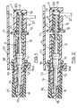
- the portion of the sprayer illustrated in the drawings is adapted for mounting on a container for liquid.
- the portion comprises a spray head 1 including a longitudinally extending bore 2 which is closed at its inner end by a wall 3, and a manually-operable valve including a two-part spool assembly 4, for controlling discharge of liquid from an inlet 21 to a discharge nozzle 14.
- the spool assembly 4 comprises a spool 5 which works in the bore 2 and has a longitudinally extending passage 6, and a hollow forward extension 7 which is closed at its forward end but which is provided adjacent to that end with a pair of diametrically arranged ports 8.
- a first sealing 'O' ring 9 of elastomeric material is received in a radial groove 10 defined between the open outer end of the bore 2 and a retainer 11, so that it surrounds the spool 5 and is in frictional engagement with it.
- a second sealing 'O' ring 12 of elastomeric material is received in a radial groove 13 provided in the extension 7 in a position inwardly of the ports 8 to seal against the wall of the nozzle 14, which is screwed onto the outer end of the extension 7.
- the nozzle 14 has a central discharge opening 15 with which the ports 8 communicate through a clearance 16 between the extension 7 and nozzle and a swirl slot in the adjacent closed end of the extension 7.
- a manually-operable member in the form of a trigger 17 fits over the spray head 1, and is coupled to the nozzle 14 by means of a fork 18 which is received in annular recess 18a in the nozzle 14.
- a spring acts between the head 1 and the trigger 17 normally to hold the valve in a closed position as shown in Figure 1 with a head 19 comprising the plain inner end of the spool 5 in engagement with a seating comprising an '0' ring seal 20 of elastomeric material supported by the wall 3 at the closed inner end of the bore 2.
- the radial inlet 21 in the wall of the head 1 is isolated from the passage 6, and external leakage of liquid from the space between the spool 5 and the bore 2 is prevented by the seal 9.
- the spray head described above can be incorporated in a hand-operated sprayer of the pressurised liquid type forming the subject of our pending Patent Applications GB-A-2084258 and 8313900.
Landscapes
- Containers And Packaging Bodies Having A Special Means To Remove Contents (AREA)
Priority Applications (4)
| Application Number | Priority Date | Filing Date | Title |
|---|---|---|---|
| GB08414805A GB2141488B (en) | 1983-06-11 | 1984-06-11 | Improvements in hand-operated sprayers |
| DE8484306168T DE3477886D1 (en) | 1984-09-10 | 1984-09-10 | Improvements in hand-operated sprayers |
| EP19840306168 EP0174401B1 (de) | 1983-06-11 | 1984-09-10 | Handbetätigte Zerstäuber |
| AT84306168T ATE42479T1 (de) | 1984-09-10 | 1984-09-10 | Handbetaetigte zerstaeuber. |
Applications Claiming Priority (3)
| Application Number | Priority Date | Filing Date | Title |
|---|---|---|---|
| GB838316027A GB8316027D0 (en) | 1983-06-11 | 1983-06-11 | Hand-operated sprayers |
| GB08414805A GB2141488B (en) | 1983-06-11 | 1984-06-11 | Improvements in hand-operated sprayers |
| EP19840306168 EP0174401B1 (de) | 1983-06-11 | 1984-09-10 | Handbetätigte Zerstäuber |
Publications (2)
| Publication Number | Publication Date |
|---|---|
| EP0174401A1 true EP0174401A1 (de) | 1986-03-19 |
| EP0174401B1 EP0174401B1 (de) | 1989-04-26 |
Family
ID=27227247
Family Applications (1)
| Application Number | Title | Priority Date | Filing Date |
|---|---|---|---|
| EP19840306168 Expired EP0174401B1 (de) | 1983-06-11 | 1984-09-10 | Handbetätigte Zerstäuber |
Country Status (2)
| Country | Link |
|---|---|
| EP (1) | EP0174401B1 (de) |
| GB (1) | GB2141488B (de) |
Citations (4)
| Publication number | Priority date | Publication date | Assignee | Title |
|---|---|---|---|---|
| FR669927A (fr) * | 1929-07-27 | 1929-11-22 | Obturateur distributeur tubulaire à mouvement rectiligne pour fluides, dans toutes applications et notamment automobile et aviation avec commande à main, ou à distance, réserve, filtre et interrupteur donjugué d'allumage électrique | |
| FR2104146A5 (de) * | 1970-08-10 | 1972-04-14 | British Oxygen Co Ltd | |
| FR2270497A1 (en) * | 1974-05-10 | 1975-12-05 | Pont A Mousson | Tap with sliding plug - has screw and nut mechanism moving plug in axial bore in body |
| GB2084258A (en) * | 1980-09-23 | 1982-04-07 | Ass Sprayers Ltd | Improvements in hand operated sprayers |
Family Cites Families (5)
| Publication number | Priority date | Publication date | Assignee | Title |
|---|---|---|---|---|
| GB295158A (en) * | 1927-11-18 | 1928-08-09 | Matti Vilho Lappalainen | An appliance for cleaning the teeth |
| US2546808A (en) * | 1947-03-22 | 1951-03-27 | Prel Inc | Pressure dispensing device |
| GB673708A (en) * | 1949-11-01 | 1952-06-11 | Nu Swift Ltd | An improved nozzle for controlling the discharge of liquids |
| DE1782388B2 (de) * | 1968-08-24 | 1973-03-15 | Credo-Stahlwarenfabrik Gustav Kracht, 5650 Solingen | Geraet zum ausschenken insbesondere von bier in dosen |
| IT1076650B (it) * | 1977-03-31 | 1985-04-27 | Massarani Giuliano | Valvola di erogazione per panna montata |
-
1984
- 1984-06-11 GB GB08414805A patent/GB2141488B/en not_active Expired
- 1984-09-10 EP EP19840306168 patent/EP0174401B1/de not_active Expired
Patent Citations (4)
| Publication number | Priority date | Publication date | Assignee | Title |
|---|---|---|---|---|
| FR669927A (fr) * | 1929-07-27 | 1929-11-22 | Obturateur distributeur tubulaire à mouvement rectiligne pour fluides, dans toutes applications et notamment automobile et aviation avec commande à main, ou à distance, réserve, filtre et interrupteur donjugué d'allumage électrique | |
| FR2104146A5 (de) * | 1970-08-10 | 1972-04-14 | British Oxygen Co Ltd | |
| FR2270497A1 (en) * | 1974-05-10 | 1975-12-05 | Pont A Mousson | Tap with sliding plug - has screw and nut mechanism moving plug in axial bore in body |
| GB2084258A (en) * | 1980-09-23 | 1982-04-07 | Ass Sprayers Ltd | Improvements in hand operated sprayers |
Also Published As
| Publication number | Publication date |
|---|---|
| EP0174401B1 (de) | 1989-04-26 |
| GB2141488A (en) | 1984-12-19 |
| GB8414805D0 (en) | 1984-07-18 |
| GB2141488B (en) | 1986-09-17 |
Similar Documents
| Publication | Publication Date | Title |
|---|---|---|
| US5771931A (en) | High pressure wear resistant pilot valve | |
| US3981479A (en) | Check valve | |
| JP2781463B2 (ja) | 冷凍システムのサービスアダプタ | |
| US5050804A (en) | Shaft seal for portable paint gun | |
| WO1994012818B1 (en) | Fire control valve with replaceable locking pin assembly | |
| MXPA01006373A (es) | Embolo de valvula solenoide. | |
| US4492320A (en) | Dispenser with an air pump mechanism | |
| US4522373A (en) | Valve detent | |
| EP1312416A2 (de) | Steuervorrichtung für Hochdruckwasser | |
| CA2143114A1 (en) | Fluid Flow Check Valve | |
| CA2189613C (en) | Pressure reduction valve | |
| US5095939A (en) | Redundant pressurizing valve | |
| US4635856A (en) | Hand-operated sprayers | |
| JP4910159B2 (ja) | 流体噴射用ガン | |
| GB2092205A (en) | Cutting bit carrier for a mineral cutting or other machine | |
| EP1158226B1 (de) | Ladeventil für Gas | |
| US5996614A (en) | Fluid valve | |
| US5483991A (en) | Valve with self-centering seat | |
| BG63685B1 (bg) | Пистолет за спрей | |
| WO1982000725A1 (en) | Fluid flow control device | |
| US6065487A (en) | Valve with different configurations for different uses | |
| EP0174401B1 (de) | Handbetätigte Zerstäuber | |
| EP0467334B1 (de) | Tragbare Farbspritzpistole | |
| US4949938A (en) | Connection arrangement | |
| US4149381A (en) | Single hand operated tool |
Legal Events
| Date | Code | Title | Description |
|---|---|---|---|
| PUAI | Public reference made under article 153(3) epc to a published international application that has entered the european phase |
Free format text: ORIGINAL CODE: 0009012 |
|
| AK | Designated contracting states |
Kind code of ref document: A1 Designated state(s): AT BE CH DE FR IT LI LU NL SE |
|
| 17P | Request for examination filed |
Effective date: 19860514 |
|
| 17Q | First examination report despatched |
Effective date: 19870220 |
|
| ITF | It: translation for a ep patent filed | ||
| GRAA | (expected) grant |
Free format text: ORIGINAL CODE: 0009210 |
|
| AK | Designated contracting states |
Kind code of ref document: B1 Designated state(s): AT BE CH DE FR IT LI LU NL SE |
|
| PG25 | Lapsed in a contracting state [announced via postgrant information from national office to epo] |
Ref country code: SE Effective date: 19890426 Ref country code: NL Effective date: 19890426 Ref country code: LI Effective date: 19890426 Ref country code: CH Effective date: 19890426 Ref country code: BE Effective date: 19890426 Ref country code: AT Effective date: 19890426 |
|
| REF | Corresponds to: |
Ref document number: 42479 Country of ref document: AT Date of ref document: 19890515 Kind code of ref document: T |
|
| REF | Corresponds to: |
Ref document number: 3477886 Country of ref document: DE Date of ref document: 19890601 |
|
| ET | Fr: translation filed | ||
| REG | Reference to a national code |
Ref country code: CH Ref legal event code: PL |
|
| PG25 | Lapsed in a contracting state [announced via postgrant information from national office to epo] |
Ref country code: LU Free format text: LAPSE BECAUSE OF NON-PAYMENT OF DUE FEES Effective date: 19890930 |
|
| NLV1 | Nl: lapsed or annulled due to failure to fulfill the requirements of art. 29p and 29m of the patents act | ||
| PLBE | No opposition filed within time limit |
Free format text: ORIGINAL CODE: 0009261 |
|
| 26N | No opposition filed | ||
| ITTA | It: last paid annual fee | ||
| PGFP | Annual fee paid to national office [announced via postgrant information from national office to epo] |
Ref country code: FR Payment date: 19970721 Year of fee payment: 14 |
|
| PGFP | Annual fee paid to national office [announced via postgrant information from national office to epo] |
Ref country code: DE Payment date: 19970917 Year of fee payment: 14 |
|
| PG25 | Lapsed in a contracting state [announced via postgrant information from national office to epo] |
Ref country code: FR Free format text: LAPSE BECAUSE OF NON-PAYMENT OF DUE FEES Effective date: 19990531 |
|
| PG25 | Lapsed in a contracting state [announced via postgrant information from national office to epo] |
Ref country code: DE Free format text: LAPSE BECAUSE OF NON-PAYMENT OF DUE FEES Effective date: 19990701 |
|
| REG | Reference to a national code |
Ref country code: FR Ref legal event code: ST |