EP0174429A2 - Dispositif pour l'aération d'eau usée ou de milieux similaires dans les bassins d'aération - Google Patents
Dispositif pour l'aération d'eau usée ou de milieux similaires dans les bassins d'aération Download PDFInfo
- Publication number
- EP0174429A2 EP0174429A2 EP85104359A EP85104359A EP0174429A2 EP 0174429 A2 EP0174429 A2 EP 0174429A2 EP 85104359 A EP85104359 A EP 85104359A EP 85104359 A EP85104359 A EP 85104359A EP 0174429 A2 EP0174429 A2 EP 0174429A2
- Authority
- EP
- European Patent Office
- Prior art keywords
- wing
- aeration
- membrane
- ventilation
- gravity
- Prior art date
- Legal status (The legal status is an assumption and is not a legal conclusion. Google has not performed a legal analysis and makes no representation as to the accuracy of the status listed.)
- Granted
Links
- 238000005273 aeration Methods 0.000 title claims abstract description 20
- 239000002351 wastewater Substances 0.000 title claims abstract description 5
- 239000012528 membrane Substances 0.000 claims abstract description 39
- XLYOFNOQVPJJNP-UHFFFAOYSA-N water Substances O XLYOFNOQVPJJNP-UHFFFAOYSA-N 0.000 claims abstract description 25
- 238000009423 ventilation Methods 0.000 claims abstract description 23
- 230000005484 gravity Effects 0.000 claims abstract description 17
- 238000000034 method Methods 0.000 claims abstract description 12
- 230000003247 decreasing effect Effects 0.000 claims abstract description 3
- 239000007788 liquid Substances 0.000 claims description 7
- 239000000463 material Substances 0.000 claims description 6
- 239000004033 plastic Substances 0.000 claims description 4
- 238000010276 construction Methods 0.000 claims description 3
- 230000003068 static effect Effects 0.000 claims description 3
- 230000001419 dependent effect Effects 0.000 claims description 2
- 229920001971 elastomer Polymers 0.000 claims description 2
- 239000011888 foil Substances 0.000 claims description 2
- 239000002184 metal Substances 0.000 claims description 2
- 229910001220 stainless steel Inorganic materials 0.000 claims description 2
- 239000010935 stainless steel Substances 0.000 claims description 2
- 239000004744 fabric Substances 0.000 claims 1
- 238000005276 aerator Methods 0.000 abstract description 10
- 238000009826 distribution Methods 0.000 abstract description 7
- 238000013461 design Methods 0.000 abstract description 5
- 238000013508 migration Methods 0.000 abstract 1
- 230000005012 migration Effects 0.000 abstract 1
- 239000011324 bead Substances 0.000 description 4
- 238000007789 sealing Methods 0.000 description 3
- 230000015572 biosynthetic process Effects 0.000 description 2
- 238000000354 decomposition reaction Methods 0.000 description 1
- 239000006185 dispersion Substances 0.000 description 1
- 239000000806 elastomer Substances 0.000 description 1
- 238000003780 insertion Methods 0.000 description 1
- 230000037431 insertion Effects 0.000 description 1
- 238000004519 manufacturing process Methods 0.000 description 1
- 230000000149 penetrating effect Effects 0.000 description 1
- 230000002093 peripheral effect Effects 0.000 description 1
- 230000002028 premature Effects 0.000 description 1
- 230000002441 reversible effect Effects 0.000 description 1
- 239000007787 solid Substances 0.000 description 1
- 230000000087 stabilizing effect Effects 0.000 description 1
- 229920003051 synthetic elastomer Polymers 0.000 description 1
- 239000005061 synthetic rubber Substances 0.000 description 1
- 230000008719 thickening Effects 0.000 description 1
- 238000012549 training Methods 0.000 description 1
- 238000009827 uniform distribution Methods 0.000 description 1
- 239000002699 waste material Substances 0.000 description 1
Images


Classifications
-
- C—CHEMISTRY; METALLURGY
- C02—TREATMENT OF WATER, WASTE WATER, SEWAGE, OR SLUDGE
- C02F—TREATMENT OF WATER, WASTE WATER, SEWAGE, OR SLUDGE
- C02F3/00—Biological treatment of water, waste water, or sewage
- C02F3/02—Aerobic processes
- C02F3/12—Activated sludge processes
- C02F3/20—Activated sludge processes using diffusers
- C02F3/201—Perforated, resilient plastic diffusers, e.g. membranes, sheets, foils, tubes, hoses
-
- B—PERFORMING OPERATIONS; TRANSPORTING
- B01—PHYSICAL OR CHEMICAL PROCESSES OR APPARATUS IN GENERAL
- B01F—MIXING, e.g. DISSOLVING, EMULSIFYING OR DISPERSING
- B01F23/00—Mixing according to the phases to be mixed, e.g. dispersing or emulsifying
- B01F23/20—Mixing gases with liquids
- B01F23/23—Mixing gases with liquids by introducing gases into liquid media, e.g. for producing aerated liquids
- B01F23/231—Mixing gases with liquids by introducing gases into liquid media, e.g. for producing aerated liquids by bubbling
- B01F23/23105—Arrangement or manipulation of the gas bubbling devices
- B01F23/2312—Diffusers
- B01F23/23124—Diffusers consisting of flexible porous or perforated material, e.g. fabric
-
- B—PERFORMING OPERATIONS; TRANSPORTING
- B01—PHYSICAL OR CHEMICAL PROCESSES OR APPARATUS IN GENERAL
- B01F—MIXING, e.g. DISSOLVING, EMULSIFYING OR DISPERSING
- B01F23/00—Mixing according to the phases to be mixed, e.g. dispersing or emulsifying
- B01F23/20—Mixing gases with liquids
- B01F23/23—Mixing gases with liquids by introducing gases into liquid media, e.g. for producing aerated liquids
- B01F23/231—Mixing gases with liquids by introducing gases into liquid media, e.g. for producing aerated liquids by bubbling
- B01F23/23105—Arrangement or manipulation of the gas bubbling devices
- B01F23/2312—Diffusers
- B01F23/23126—Diffusers characterised by the shape of the diffuser element
- B01F23/231262—Diffusers characterised by the shape of the diffuser element having disc shape
-
- Y—GENERAL TAGGING OF NEW TECHNOLOGICAL DEVELOPMENTS; GENERAL TAGGING OF CROSS-SECTIONAL TECHNOLOGIES SPANNING OVER SEVERAL SECTIONS OF THE IPC; TECHNICAL SUBJECTS COVERED BY FORMER USPC CROSS-REFERENCE ART COLLECTIONS [XRACs] AND DIGESTS
- Y02—TECHNOLOGIES OR APPLICATIONS FOR MITIGATION OR ADAPTATION AGAINST CLIMATE CHANGE
- Y02W—CLIMATE CHANGE MITIGATION TECHNOLOGIES RELATED TO WASTEWATER TREATMENT OR WASTE MANAGEMENT
- Y02W10/00—Technologies for wastewater treatment
- Y02W10/10—Biological treatment of water, waste water, or sewage
-
- Y—GENERAL TAGGING OF NEW TECHNOLOGICAL DEVELOPMENTS; GENERAL TAGGING OF CROSS-SECTIONAL TECHNOLOGIES SPANNING OVER SEVERAL SECTIONS OF THE IPC; TECHNICAL SUBJECTS COVERED BY FORMER USPC CROSS-REFERENCE ART COLLECTIONS [XRACs] AND DIGESTS
- Y10—TECHNICAL SUBJECTS COVERED BY FORMER USPC
- Y10S—TECHNICAL SUBJECTS COVERED BY FORMER USPC CROSS-REFERENCE ART COLLECTIONS [XRACs] AND DIGESTS
- Y10S261/00—Gas and liquid contact apparatus
- Y10S261/70—Sewage aerators; diffusers
Definitions
- the invention relates to a method for the intermittent aeration of liquids, including waste 'water or the like media in the aeration tank by means of an arranged below the liquid surface aerator consisting of one or more fixed by a frame construction dense support film (s) with an air supply port, said carrier film (n) is covered with a preferably elastic membrane partially perforated by punctures, cuts or perforations.
- an air distributor provided for exercising an aeration method for fine-bubble aeration of water is known, the criterion of which is the arrangement of a dense and a perforated film lying thereon in an oppositely directed angular frame, which have the function of a tenter frame , and in the further lying under the non-perforated film, supporting webs are connected. Above the perforated film, at a slight distance from this film, there are further stabilizing webs which are offset by 90 ° to the lower webs and are evenly distributed over the surface.
- An air distributor designed in this way does justice to the task given here in that the most uniform distribution of air can be achieved over the entire distributor surface.
- the training has the disadvantage of the need for a relatively heavy, stiffened, weight-consuming double frame construction, which makes manipulation of the aerator in the aeration basin difficult.
- Another disadvantage of this concept is the position of the level of the aeration surface relative to the water surface, which is also weight-based and cannot be changed during operation.
- devices are known whose supporting bodies are provided with air passage openings and which are covered with a perforated air distribution film or are covered by a perforated hose, and which generally require the arrangement of additional tensioning means for fixing the position of the hoses or the films.
- the solution to this problem according to the invention provides that the air essentially perpendicular to a rigid, self-supporting, or porous or provided with openings, covered by an elastic membrane, such as in its center of gravity or in series distributed over a line of gravity and in at least one deflection area, and to the opposite This periphery is offset by a small amount with a decreasing pressure into the water to be aerated, with a possible ventilation surface inclined and / or pivotable up to + 90 ° to the water surface.
- a reverse arrangement is possible in the same way, but special care is required to fix the membrane in the air inlet area, and the formation of the wing from the air inlet area to the periphery is appropriately curved inward, that is to say is concave.
- the dispersion and the speed of the complete or partial decomposition of the air introduced can be further improved in that the ventilation surface and thus the wing rotates around its center of gravity and transfers the air into a widening vortex wake.
- the membrane is usually made of elastomer, in particular synthetic rubber, since its elasticity behavior can be adjusted over a wide range.
- the membrane In order to know the elastic behavior of the membrane from the air inflow area to the outer edge, the membrane can have different thicknesses.
- the air supply connection connected to the airfoil is a pipe socket, occasionally provided with transverse outlet openings, to which the membrane is connected by clamps.
- Another proposal provides, e.g. thicken the round membrane in the center so that it is attached to the wing with a clamping washer with a bead and a screw and is screwed to the air supply connector.
- a fastening of the membrane with the wing on the outer edge provides that the membrane is provided with a circumferential sleeve that wraps around the wing as a sealing sleeve, with a groove being incorporated in the sleeve in some cases, in which a circumferential clamp can be attached .
- inflatable and / or fixed floats are attached to it.
- the ventilation surface is inclined or curved at an angle C of up to + 90 ° to the liquid surface and that it can be pivotable.
- the normally round or rectangular wings can be provided with openings of any shape.
- the membrane consists of woven or knitted plastic, or that the elastic membrane is a metal foil.
- the membrane has perforations in the form of perforations, slit, star or cross-shaped incisions through which the air is introduced into the water in fine bubbles. In the area of openings in the wing, this perforation should preferably be exposed. The perforation should be staggered to give the membrane the greatest possible stability.
- lower point and “lowest limit” each refer to the peak limitation (point or line) and can be viewed both as downwards and upwards.
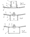
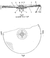
- the air supply lines 1, as represented by FIGS. 1, 2 and 5, relate to an insertion nozzle directed from above towards the rigid airfoil 2, generally arranged in the center of gravity 10, which is generally fastened in the center of gravity of the surface, and how represented by the drawings, is provided with transverse exit openings 1.1 directed into the deflection area 3.
- the support surface 2 rests on the elastic, perforated membrane 4, which is fixed along the periphery 12 by a clamping device 5 and on the connecting piece of the air supply by a clamp 6.
- a clamping device 5 In the case of an air supply according to FIG. 6, an internally threaded socket is also connected as an air inlet from below of the wing 2, and the portion of the wing 2 enclosed by the nozzle is opened.
- the connection to the membrane 4 is made by means of a clamping bridge 7 which is fixed flush in the nozzle upwards.
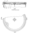
- FIGS. 3 and 4 provide a channel 1.2, which is open to the wing 2 and has a main line of extension, which is generally identical to a line of gravity 11, in which the air is conducted at any point.
- the connection with the membrane 4 is made lemm 7 bridges over the flush mounted in the channel to the airfoil boundary K.
- the static stability of the support surface 2 is adjacent to the material selection and its thickness is dimensioned, on the degree of H öhenverage 13 between the depth limit in the focus 10 or a heavy line 11 and the periphery 12 of the support surface 2 depends.
- the shape of the inclination can be seen from the cross-sectional lines through the wing; it runs generally in a straight line, but can also have a circular shape in the direction of the elevation: shaped / concave / convex or circular / dome-shaped.
- the device can be provided with at least one inflatable or solid float 8/9, so that the aerator can be transported to the surface even when the pool is full.
- the elastic floats are removed via a pipe or before removing the ventilation device Hose line filled and thus float to the water surface when the locking device of the aeration device in the pool is removed.
- FIGS. 8 and 9 provide for round aerators in another embodiment as described above, the air supply 1 with an inlet nozzle directed from below towards the rigid airfoil 2, generally arranged in the center of gravity 10, which is generally in the center of gravity of the surface is attached.
- the support surface 2 rests on the elastic, perforated membrane 4, which is connected to the rigid support surface along the periphery 12 with a sealing collar 14.
- This sealing sleeve 14 has a circumferential groove 15, in which a circumferential clamp 16 is attached. In the center of the membrane 4, this has a thickening 17, where it is connected to the rigid support surface 2 by a clamping disk with a bead 18 and a screw 19.
- a threaded connection piece with collar 20 is provided, in which the support surface 2 rests with the membrane 4 and is held with a screw collar 21 and a pressure ring 22.
- the position of the ventilation device is not shown.
- the inflatable floating bodies ultimately having the advantage that, with an equilibrium arrangement and the same degree of filling, the height of the aerator can ultimately be set practically in a floating manner without supporting elements.
- breakthroughs through this level for example in the area of the air supply 1, can be provided, these having to be sealed between the wing and membrane against the ingress of water.
- the rigidity of the wings can be increased in some cases by embossed beads, although one must take into account the coverage of the beads by the membrane 4 when the perforation is formed.
Landscapes
- Chemical & Material Sciences (AREA)
- Life Sciences & Earth Sciences (AREA)
- Chemical Kinetics & Catalysis (AREA)
- Biodiversity & Conservation Biology (AREA)
- Microbiology (AREA)
- Hydrology & Water Resources (AREA)
- Engineering & Computer Science (AREA)
- Environmental & Geological Engineering (AREA)
- Water Supply & Treatment (AREA)
- Organic Chemistry (AREA)
- Aeration Devices For Treatment Of Activated Polluted Sludge (AREA)
Priority Applications (2)
| Application Number | Priority Date | Filing Date | Title |
|---|---|---|---|
| AT85104359T ATE41765T1 (de) | 1984-09-12 | 1985-04-10 | Vorrichtung zur belueftung von abwasser oder dgl. medien in belueftungsbecken. |
| FI851783A FI93638C (fi) | 1984-09-12 | 1985-05-07 | Laitteisto jäteveden tms. nesteiden ilmastukseen |
Applications Claiming Priority (2)
| Application Number | Priority Date | Filing Date | Title |
|---|---|---|---|
| EP84710032 | 1984-09-12 | ||
| EP84710032 | 1984-09-12 |
Publications (3)
| Publication Number | Publication Date |
|---|---|
| EP0174429A2 true EP0174429A2 (fr) | 1986-03-19 |
| EP0174429A3 EP0174429A3 (en) | 1986-06-04 |
| EP0174429B1 EP0174429B1 (fr) | 1989-03-29 |
Family
ID=8192983
Family Applications (1)
| Application Number | Title | Priority Date | Filing Date |
|---|---|---|---|
| EP85104359A Expired EP0174429B1 (fr) | 1984-09-12 | 1985-04-10 | Dispositif pour l'aération d'eau usée ou de milieux similaires dans les bassins d'aération |
Country Status (3)
| Country | Link |
|---|---|
| US (2) | US4631134A (fr) |
| EP (1) | EP0174429B1 (fr) |
| DE (1) | DE3569098D1 (fr) |
Cited By (4)
| Publication number | Priority date | Publication date | Assignee | Title |
|---|---|---|---|---|
| EP0346109A1 (fr) * | 1988-06-08 | 1989-12-13 | Campbell, Elisabeth Mary | Appareil pour la circulation et l'échange de gaz dans des liquides |
| WO1992019546A1 (fr) * | 1991-05-03 | 1992-11-12 | John James Todd | Appareil de gazeification de liquides |
| EP0589833A1 (fr) * | 1992-09-22 | 1994-03-30 | Huber + Suhner AG Kabel-, Kautschuk-, Kunststoffwerke | Procédé et dispositif de fabrication de membranes de gazéification |
| EP0704237A2 (fr) | 1994-09-29 | 1996-04-03 | Karl-Heinz SCHÜSSLER | Dispositif pour l'introduction de gaz |
Families Citing this family (29)
| Publication number | Priority date | Publication date | Assignee | Title |
|---|---|---|---|---|
| EP0174429B1 (fr) * | 1984-09-12 | 1989-03-29 | Karl-Heinz SCHÜSSLER | Dispositif pour l'aération d'eau usée ou de milieux similaires dans les bassins d'aération |
| DE3709910C2 (de) * | 1987-03-26 | 1997-02-06 | Jaeger Arnold | Vorrichtung zum Belüften von Wasser |
| DE3710910C2 (de) * | 1987-04-01 | 1996-02-01 | Jaeger Arnold | Vorrichtung zum Belüften von Wasser |
| DE3819305A1 (de) * | 1988-06-03 | 1989-12-07 | Ott Rita | Begasungseinrichtung |
| DE8807929U1 (de) * | 1988-06-20 | 1988-08-18 | Messner, Rudolf, 8555 Adelsdorf | Verbindungsvorrichtung |
| US4961854A (en) * | 1988-06-30 | 1990-10-09 | Envirex Inc. | Activated sludge wastewater treatment process |
| US5093047A (en) * | 1990-01-18 | 1992-03-03 | Roediger Pittsburgh, Inc. | Gas diffuser |
| US4981623A (en) * | 1990-03-12 | 1991-01-01 | Aquatec, Inc. | Diffuser for aeration basin |
| DE9006868U1 (de) * | 1990-06-19 | 1990-10-04 | Venator Inc., Victor, Id. | Vorrichtung zum Belüften von Wasser |
| US5133862A (en) * | 1991-01-31 | 1992-07-28 | Fmc Corporation | Flexible membrane diffuser |
| DE4104287A1 (de) * | 1991-02-13 | 1992-08-20 | Schumacher Umwelt Trenntech | Langplattenbeluefter |
| US5211856A (en) * | 1992-03-06 | 1993-05-18 | Hanshi Shen | Method of oil/water separation and device for purification of oil |
| US5192467A (en) * | 1992-07-02 | 1993-03-09 | Parkson Corporation | Aeration panel structure |
| US5316671A (en) * | 1993-01-21 | 1994-05-31 | Murphy D Thomas | Submersible aeration train and aeration apparatus for biological purification of sewage |
| DE9415775U1 (de) * | 1994-09-29 | 1994-12-08 | Vogel, Michaela, 61169 Friedberg | Begasungsvorrichtung |
| DE19735188A1 (de) * | 1997-08-14 | 1999-02-18 | Gummi Jaeger Kg Gmbh & Cie | Wasserbelüfter |
| US7434362B2 (en) | 2001-07-20 | 2008-10-14 | Unirac, Inc. | System for removably and adjustably mounting a device on a surface |
| US8002249B2 (en) | 2002-08-13 | 2011-08-23 | Itt Manufacturing Enterprises, Inc. | Strip diffuser |
| AU2003256405A1 (en) * | 2002-08-13 | 2004-02-25 | Itt Manufacturing Enterprises, Inc. | Strip diffuser pct i |
| US7600349B2 (en) | 2003-02-26 | 2009-10-13 | Unirac, Inc. | Low profile mounting system |
| WO2005082506A1 (fr) * | 2004-02-24 | 2005-09-09 | Usfilter Corporation | Motif a rainures pour membrane de diffuseur d'aeration |
| AT413380B (de) * | 2004-05-28 | 2006-02-15 | Meyer Udo Dipl Ing | Einrichtung zum befestigen einer perforierten belüfter-membran |
| US8556238B2 (en) * | 2006-12-29 | 2013-10-15 | Econity Co., Ltd. | Diffuser for aeration |
| KR100778491B1 (ko) * | 2006-12-29 | 2007-11-28 | 주식회사 케이엠에스 | 폭기용 산기관 |
| US8371561B2 (en) | 2010-04-12 | 2013-02-12 | Xylem Ip Holdings Llc | Aeration diffuser assembly end seal |
| DE102010029754A1 (de) * | 2010-06-07 | 2011-12-08 | Invent Umwelt- Und Verfahrenstechnik Ag | Vorrichtung zum Begasen von Flüssigkeiten |
| US9758403B2 (en) * | 2011-11-28 | 2017-09-12 | Walter J. Wasseluk | Method and apparatus for treatment of water-borne contaminants |
| US9862628B2 (en) | 2013-10-04 | 2018-01-09 | Ovivo Inc. | Adjustable variable bubble size aeration for submerged membrane air scour |
| CA180546S (en) | 2017-09-29 | 2019-04-11 | Aquatec Maxcon Pty Ltd | Base member for an air diffuser |
Family Cites Families (10)
| Publication number | Priority date | Publication date | Assignee | Title |
|---|---|---|---|---|
| GB1212825A (en) * | 1967-04-21 | 1970-11-18 | Activated Sludge Ltd | Improvements in or relating to a porous diffuser and mounting means therefor |
| US3911064A (en) * | 1971-04-08 | 1975-10-07 | Union Carbide Corp | System for gas sparging into liquid |
| US3768788A (en) * | 1971-04-21 | 1973-10-30 | S Candel | Liquid aeration method and apparatus |
| US3997634A (en) * | 1973-10-09 | 1976-12-14 | Downs Ernest W | Diffuser assembly |
| US4070279A (en) * | 1976-09-13 | 1978-01-24 | Armstrong Edward T | Eductor for dissolving gases in liquids |
| DE2701656C2 (de) * | 1977-01-17 | 1979-02-08 | Schreiber, August, Dr.-Ing., 3000 Hannover | Einrichtung zur intermittierenden Belüftung von Abwasser |
| US4288394A (en) * | 1978-10-19 | 1981-09-08 | Water Pollution Control Corp. | Sewage aeration system |
| DE2942607C2 (de) * | 1979-10-22 | 1982-08-26 | Rudolf 8551 Adelsdorf Messner | Luftverteiler zum feinblasigen Belüften von Wasser |
| DE3316140A1 (de) * | 1982-05-03 | 1983-11-03 | Techtransfer GmbH & Co KG, 7000 Stuttgart | Flaechenbeluefter zum feinblasigen begasen von fluessigkeiten |
| EP0174429B1 (fr) * | 1984-09-12 | 1989-03-29 | Karl-Heinz SCHÜSSLER | Dispositif pour l'aération d'eau usée ou de milieux similaires dans les bassins d'aération |
-
1985
- 1985-04-10 EP EP85104359A patent/EP0174429B1/fr not_active Expired
- 1985-04-10 DE DE8585104359T patent/DE3569098D1/de not_active Expired
- 1985-05-10 US US06/732,640 patent/US4631134A/en not_active Expired - Fee Related
-
1986
- 1986-09-23 US US06/910,497 patent/US4734191A/en not_active Expired - Fee Related
Cited By (8)
| Publication number | Priority date | Publication date | Assignee | Title |
|---|---|---|---|---|
| EP0346109A1 (fr) * | 1988-06-08 | 1989-12-13 | Campbell, Elisabeth Mary | Appareil pour la circulation et l'échange de gaz dans des liquides |
| WO1992019546A1 (fr) * | 1991-05-03 | 1992-11-12 | John James Todd | Appareil de gazeification de liquides |
| US5458771A (en) * | 1991-05-03 | 1995-10-17 | Todd; John J. | Apparatus for the gasification of liquids |
| AU667304B2 (en) * | 1991-05-03 | 1996-03-21 | John James Todd | Apparatus for the gasification of liquids |
| EP0589833A1 (fr) * | 1992-09-22 | 1994-03-30 | Huber + Suhner AG Kabel-, Kautschuk-, Kunststoffwerke | Procédé et dispositif de fabrication de membranes de gazéification |
| US5410925A (en) * | 1992-09-22 | 1995-05-02 | Huber+Auhner Ag | Method of making an aerator membrane |
| EP0704237A2 (fr) | 1994-09-29 | 1996-04-03 | Karl-Heinz SCHÜSSLER | Dispositif pour l'introduction de gaz |
| EP0704237A3 (fr) * | 1994-09-29 | 1996-06-12 | Schuessler Karl Heinz | Dispositif pour l'introduction de gaz |
Also Published As
| Publication number | Publication date |
|---|---|
| US4734191A (en) | 1988-03-29 |
| EP0174429A3 (en) | 1986-06-04 |
| EP0174429B1 (fr) | 1989-03-29 |
| DE3569098D1 (en) | 1989-05-03 |
| US4631134A (en) | 1986-12-23 |
Similar Documents
| Publication | Publication Date | Title |
|---|---|---|
| EP0174429A2 (fr) | Dispositif pour l'aération d'eau usée ou de milieux similaires dans les bassins d'aération | |
| EP0309474B1 (fr) | Procede et dispositif pour la gazeification des liquides en fines bulles et sur une grande surface | |
| DE3410267C2 (fr) | ||
| DE2942607C2 (de) | Luftverteiler zum feinblasigen Belüften von Wasser | |
| DE1071054B (de) | Verteilervorrichtung zur Dispersion von äsen in Flüssigkeiten | |
| DE4001201C1 (fr) | ||
| DE2513547A1 (de) | Einrichtung zum belueften von abwasser | |
| DE2925457C2 (fr) | ||
| EP0363865B1 (fr) | Dispositif d'aération | |
| EP0171452B1 (fr) | Diffuseur à bulles fines pour aération d'eau | |
| EP1366807A2 (fr) | Dispositif pour l'aération de l'eau | |
| DE2035651C3 (de) | Einrichtung zum feinblasigen Belüften von Abwasser | |
| DE3441731A1 (de) | Belueftungselement | |
| DE2261994A1 (de) | Einrichtung zum feinblasigen belueften von abwasser | |
| DE4013239C2 (fr) | ||
| AT409623B (de) | Flotationsanlage | |
| EP2143691A2 (fr) | Bioréacteur à membrane et procédé destinés au traitement d'eaux usées | |
| DE8426854U1 (de) | Vorrichtung zur Belüftung von Abwasser oder dgl. Medien in Belüftungsbecken | |
| DE10203780A1 (de) | Vorrichtung zum Belüften von Wasser | |
| EP0806400A1 (fr) | Aérateur courbé | |
| DE3627665C2 (fr) | ||
| DE60035764T2 (de) | Haltevorrichtung für eine Fahne oder ein Schild an einem flexiblen Mast | |
| DE3401161C2 (fr) | ||
| DE3710739A1 (de) | Flaechenbeluefter | |
| DE2450837A1 (de) | Verfahren und vorrichtung zum einleiten von gasen in eine fluessigkeitsmasse |
Legal Events
| Date | Code | Title | Description |
|---|---|---|---|
| PUAI | Public reference made under article 153(3) epc to a published international application that has entered the european phase |
Free format text: ORIGINAL CODE: 0009012 |
|
| AK | Designated contracting states |
Kind code of ref document: A2 Designated state(s): AT BE CH DE FR GB IT LI LU NL SE |
|
| PUAL | Search report despatched |
Free format text: ORIGINAL CODE: 0009013 |
|
| AK | Designated contracting states |
Kind code of ref document: A3 Designated state(s): AT BE CH DE FR GB IT LI LU NL SE |
|
| 17P | Request for examination filed |
Effective date: 19861203 |
|
| 17Q | First examination report despatched |
Effective date: 19880224 |
|
| GRAA | (expected) grant |
Free format text: ORIGINAL CODE: 0009210 |
|
| AK | Designated contracting states |
Kind code of ref document: B1 Designated state(s): AT BE CH DE FR GB IT LI LU NL SE |
|
| REF | Corresponds to: |
Ref document number: 41765 Country of ref document: AT Date of ref document: 19890415 Kind code of ref document: T |
|
| ITF | It: translation for a ep patent filed | ||
| REF | Corresponds to: |
Ref document number: 3569098 Country of ref document: DE Date of ref document: 19890503 |
|
| ET | Fr: translation filed | ||
| GBT | Gb: translation of ep patent filed (gb section 77(6)(a)/1977) | ||
| PLBE | No opposition filed within time limit |
Free format text: ORIGINAL CODE: 0009261 |
|
| STAA | Information on the status of an ep patent application or granted ep patent |
Free format text: STATUS: NO OPPOSITION FILED WITHIN TIME LIMIT |
|
| 26N | No opposition filed | ||
| ITTA | It: last paid annual fee | ||
| PGFP | Annual fee paid to national office [announced via postgrant information from national office to epo] |
Ref country code: LU Payment date: 19930324 Year of fee payment: 9 |
|
| PGFP | Annual fee paid to national office [announced via postgrant information from national office to epo] |
Ref country code: BE Payment date: 19930406 Year of fee payment: 9 |
|
| PGFP | Annual fee paid to national office [announced via postgrant information from national office to epo] |
Ref country code: AT Payment date: 19930430 Year of fee payment: 9 |
|
| EPTA | Lu: last paid annual fee | ||
| PG25 | Lapsed in a contracting state [announced via postgrant information from national office to epo] |
Ref country code: LU Free format text: LAPSE BECAUSE OF NON-PAYMENT OF DUE FEES Effective date: 19940410 Ref country code: AT Effective date: 19940410 |
|
| PG25 | Lapsed in a contracting state [announced via postgrant information from national office to epo] |
Ref country code: BE Effective date: 19940430 |
|
| BERE | Be: lapsed |
Owner name: SCHUSSLER KARL HEINZ Effective date: 19940430 |
|
| EAL | Se: european patent in force in sweden |
Ref document number: 85104359.6 |
|
| PGFP | Annual fee paid to national office [announced via postgrant information from national office to epo] |
Ref country code: FR Payment date: 19960417 Year of fee payment: 12 |
|
| PGFP | Annual fee paid to national office [announced via postgrant information from national office to epo] |
Ref country code: SE Payment date: 19960422 Year of fee payment: 12 Ref country code: GB Payment date: 19960422 Year of fee payment: 12 |
|
| PGFP | Annual fee paid to national office [announced via postgrant information from national office to epo] |
Ref country code: DE Payment date: 19960424 Year of fee payment: 12 |
|
| PGFP | Annual fee paid to national office [announced via postgrant information from national office to epo] |
Ref country code: CH Payment date: 19960524 Year of fee payment: 12 |
|
| PGFP | Annual fee paid to national office [announced via postgrant information from national office to epo] |
Ref country code: NL Payment date: 19960529 Year of fee payment: 12 |
|
| PG25 | Lapsed in a contracting state [announced via postgrant information from national office to epo] |
Ref country code: GB Effective date: 19970410 |
|
| PG25 | Lapsed in a contracting state [announced via postgrant information from national office to epo] |
Ref country code: SE Effective date: 19970411 |
|
| PG25 | Lapsed in a contracting state [announced via postgrant information from national office to epo] |
Ref country code: LI Free format text: LAPSE BECAUSE OF NON-PAYMENT OF DUE FEES Effective date: 19970430 Ref country code: CH Free format text: LAPSE BECAUSE OF NON-PAYMENT OF DUE FEES Effective date: 19970430 |
|
| PG25 | Lapsed in a contracting state [announced via postgrant information from national office to epo] |
Ref country code: NL Effective date: 19971101 |
|
| GBPC | Gb: european patent ceased through non-payment of renewal fee |
Effective date: 19970410 |
|
| REG | Reference to a national code |
Ref country code: CH Ref legal event code: PL |
|
| PG25 | Lapsed in a contracting state [announced via postgrant information from national office to epo] |
Ref country code: FR Free format text: LAPSE BECAUSE OF NON-PAYMENT OF DUE FEES Effective date: 19971231 |
|
| PG25 | Lapsed in a contracting state [announced via postgrant information from national office to epo] |
Ref country code: DE Free format text: LAPSE BECAUSE OF NON-PAYMENT OF DUE FEES Effective date: 19980101 |
|
| NLV4 | Nl: lapsed or anulled due to non-payment of the annual fee |
Effective date: 19971101 |
|
| EUG | Se: european patent has lapsed |
Ref document number: 85104359.6 |
|
| REG | Reference to a national code |
Ref country code: FR Ref legal event code: ST |