EP0174445A2 - Méthode et appareil de charge rapide d'une batterie - Google Patents
Méthode et appareil de charge rapide d'une batterie Download PDFInfo
- Publication number
- EP0174445A2 EP0174445A2 EP85107412A EP85107412A EP0174445A2 EP 0174445 A2 EP0174445 A2 EP 0174445A2 EP 85107412 A EP85107412 A EP 85107412A EP 85107412 A EP85107412 A EP 85107412A EP 0174445 A2 EP0174445 A2 EP 0174445A2
- Authority
- EP
- European Patent Office
- Prior art keywords
- charging
- voltage
- battery
- limit value
- charging process
- Prior art date
- Legal status (The legal status is an assumption and is not a legal conclusion. Google has not performed a legal analysis and makes no representation as to the accuracy of the status listed.)
- Withdrawn
Links
Images
Classifications
-
- H—ELECTRICITY
- H02—GENERATION; CONVERSION OR DISTRIBUTION OF ELECTRIC POWER
- H02J—ELECTRIC POWER NETWORKS; CIRCUIT ARRANGEMENTS OR SYSTEMS FOR SUPPLYING OR DISTRIBUTING ELECTRIC POWER; SYSTEMS FOR STORING ELECTRIC ENERGY
- H02J7/00—Circuit arrangements for charging or discharging batteries or for supplying loads from batteries
- H02J7/90—Regulation of charging or discharging current or voltage
- H02J7/96—Regulation of charging or discharging current or voltage in response to battery voltage
Definitions
- the invention relates to a method and an associated device according to the preamble of the main claim.
- a charger for batteries is known from DE-B 21 14 100.
- the battery charging takes place in this method in such a way that the charging current is interrupted when the gassing voltage of the battery is reached and is switched on again at a correspondingly lower threshold value until the charger is off the battery is disconnected.
- a device for rapid charging of batteries is widespread on the market, in which the charging process is controlled by means of a so-called pole switch.
- the charging process is carried out in such a way that when a predetermined limit value for the battery voltage or the gassing voltage of a battery cell multiplied by the number of cells is reached, a switchover to a reduced charging current takes place, which is maintained for a predetermined period of time. If the voltage limit is not reached, the charging process is interrupted after a predetermined maximum charging time.
- the method according to the invention with the characterizing features of the main claim has the advantage that a relatively simple and inexpensive device enables rapid charging of batteries, in which one achieves a favorable compromise between the largest possible full charge and the lowest possible overcharge of the battery. This is made possible in particular by the fact that the recharging of the battery takes place in a controlled manner with a reduced charging current, the so-called normal charging current, the terminal voltage of the battery being monitored and the charging process being interrupted when a predetermined, higher limit value is reached when the battery has reached the highest possible charging level is without any significant overloading of the same.
- the measures listed in the subclaims enable advantageous developments and improvements of the method specified in the main claim and a suitable design of the associated device Lich. It has proven to be advantageous if, in the method according to the invention, the limit value of the permissible battery voltage is raised in a manner known per se during a first period of time (0 - t0) that begins with the charging process, in order to avoid undesired shutdowns due to an increase in voltage due to sulfation the battery.
- the method is particularly simplified by the use of a counter put into operation by one of the threshold value switches for reversing the battery voltage to the various limit values, which takes place at predetermined times.
- the meter expediently receives its pulses from a pulse shaper which is supplied by the AC network.
- the rapid charging process is preferably terminated at the same time (t1) as the switching of the limit value of the battery voltage to the second, higher limit value (U2). This period of time is relatively short, so that the charging process is interrupted early if the battery is defective. This shortening of the rapid charging process allows the recharging to be extended with a reduced current (normal charge), the termination of which also takes place at a fixed point in time (t2) if the second limit value (U2) of the battery voltage is not reached.
- a voltage proportional to the battery voltage is applied to an input of three threshold switches (I, II, III), the other inputs of which are supplied with a reference voltage (UR) and the outputs of which the charging process when the battery is connected to the pole start on the one hand via a counter (Z) and on the other hand control via a logic (L) depending on the level of the battery voltage.
- a first threshold switch is provided which starts the charging process via a counter, while a second threshold switch controls the rapid charging process and a third threshold switch controls the normal charging process.
- the changeover to lower the voltage limit shortly after the start of the charging process takes place via the second threshold switch, the switching threshold of which can be reversed by a signal from the counter to lower the voltage limit (U3, U2).
- the second threshold switch also expediently switches over from the rapid charging process to the normal charging process when the first limit value (U1) of the battery voltage is reached, a switching device in the primary circuit of the transformer preferably being actuated to increase the primary winding number of the transformer and thus to reduce the battery charging current.
- the charging process is terminated via a third limit switch which, after the battery voltage has risen to the second limit (U2), actuates a switching device between the rectifier and the battery via the logic (L).
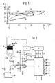
- FIG. 1 shows a functional diagram which shows the course of the battery voltage as a function of time for various charging processes
- FIG. 2 shows a basic circuit diagram of a device for carrying out the proposed charging process.
- Figure 1 shows the course of the voltage on a battery cell, representative of the course of the battery voltage on the outer terminals of the battery, depending on the time.
- three different limit values for the battery voltage are defined, namely the gassing voltage U1 of a battery cell with 2.4 volts as the first limit value in the range between to and t1, an increased limit value U2 with 2.5 volts per cell, which defines the end of the normal charging process and a third limit value U3 with 2.6 volts per cell at the start of the charging process.
- the limit value U2 applies in the range between t1 and t2, the third limit value U3 in the range between the start of charging and to.
- to corresponds to a duration of 10 minutes t1 to a duration of 1.5 hours and t2 to a duration of 3 hours.
- Curve A shows the course of the cell voltage on a defective battery, the gassing voltage U1 not being reached until time t1 and the charging process being interrupted at this time.
- Curve B shows the course of the voltage across a cell of a good, approximately half-charged battery.
- the cell voltage rises within about 25 minutes to the first limit value U1, which corresponds to the gassing voltage.
- the charging current is reduced, as a result of which the cell voltage first drops and then rises again until the second limit value U2 of the cell voltage of 2.5 volts is reached after about two hours.
- the second limit value U2 is reached, the charging process is ended.
- Curve C shows the course of the cell voltage of a sulfated, empty battery.
- the third limit value U3 has an effect here because the cell voltage at the beginning of the charge exceeds the gassing voltage or the first limit value U1 within the first 10 minutes.
- the device is not switched off at the start of the charging process until the cell voltage reaches the first limit value U1 after approximately one hour and ten minutes.
- the changeover from rapid charging to normal charging takes place, which is ended after approximately two hours and 45 minutes by reaching the second limit value U2.
- curve D shows the course of the charging voltage on a cell of a good but empty battery.
- the cell voltage initially rises gradually until the first limit value U1 is reached after approx. 1 hour and 20 minutes, then there is a switch from quick charge to normal charge with reduced current and again a decreasing terminal voltage, until after 3 hours the charging process due to the passage of time is ended.
- a switching device for performing the method according to the invention is shown.
- a transformer 10 is connected with its primary winding to the AC line voltage, its secondary winding is at the input of a rectifier 11.
- a changeover switch a is provided in the supply line to the primary winding, the switch contact of which in the rest position establishes the connection to the end point a1 of the primary winding, while in the Working situation a tap a2 of the primary winding is contacted.
- the tap a2 corresponds to the quick charge switch position, the end point a1 to the normal charge.
- the output of the rectifier 11 is connected via lines 12 and 13 and via terminals 14 and 15 to the positive and negative poles of a battery 16.
- a normally open contact of a switching device b is provided, which interrupts the supply line to the battery 16 at the end of the charging process.
- the changeover switch a and the switching device b can also be realized in a different way, for example by means of semiconductor switching devices.
- the terminal 14 and the positive pole of the battery 16 are connected to a voltage divider consisting of two resistors 17 and 18, from a connection point 19 between the resistors 17 and 18, lines lead to a smoothing capacitor 20 and to the inverting input of a first threshold switch I and to the non-inverting ones Inputs of threshold switches II and III.
- the non-inverting input of the threshold switch 1 and the inverting inputs of the threshold circuits II and III are connected together to a reference voltage, which can be obtained, for example, via an auxiliary transformer and a Zener diode.
- the reference voltage Ur is on the order of about 5 to 6 volts. Switching to other battery voltages takes place by changing the voltage divider from resistors 17 and 18.
- a pulse shaper I is also connected to the input-side AC voltage network, the pulses of which are emitted to a counter Z. This is started by a LOW signal at the output of the threshold switch I.
- the latter also serves as reverse polarity protection for the connection of the battery 16, since that LOW signal appears at its output only when at its invertie
- the input has a voltage of at least 0.15 volts per cell, ie a voltage of at least 0.9 volts for a 12 volt battery.
- Signal lines 21, 22 and 23 lead from the counter Z to a linking logic L and a further signal line parallel to the signal line 23 to the threshold switch II.
- the control lines A and B for the changeover switch a and the switching device b are indicated.
- Further inputs of logic L are connected to the outputs of threshold switches II and III, while signal devices in the form of light-emitting diodes 25 to 30 are connected to further outputs of logic L.
- the cathodes of the light emitting diodes 25 to 30 are connected to ground together. They signal the following operating states: LED 25 indicates the operational readiness of the charging device, i.e.
- the light-emitting diode 26 indicates the rapid charge
- the light-emitting diode 27 the normal charge
- the light-emitting diode 28 signals the end of the charging process after the switching device b has been opened
- the light-emitting diode 29 signals a fault in the charge, for example if, according to curve A, the first limit value of the battery voltage or cell voltage is not reached and the light-emitting diode 30 signals a fault in the charger, e.g. an excess temperature on the transformer or on the rectifier.
- the threshold value U3 for switching the threshold switch II is initially at a threshold voltage of 2.6 volts per cell of the battery, so that in case C according to FIG. 1 the rapid charging process takes place without switching off because the voltage is exceeded.
- the counter Z sends a signal to the threshold switch II via the signal lines 23 and 24 and reduces its switching threshold to the gassing voltage of the battery of 2.4 volts per cell, which corresponds to the first limit value U1 of the battery voltage.
- the charging process now runs in accordance with the various curves A to C in FIG. 1 up to time t1 at the latest.
- the logic L is brought to an end via the signal line 22 by emitting a signal via the control line B, as a result of which the switching device b interrupts the charging current.
- the charging process is terminated when the second limit value U2 of the battery voltage or the cell voltage is reached in accordance with curves B and C. This is done in that a potential corresponding to the second limit value U2 appears at the non-inverting input of the threshold value switch III and is applied via its output HIGH signal causes the logic L via the control line B to actuate the switching device b and thereby end the charging process.
- the capacitor 20 connected to the connection point 19 serves to smooth the control voltage.
Landscapes
- Engineering & Computer Science (AREA)
- Power Engineering (AREA)
- Charge And Discharge Circuits For Batteries Or The Like (AREA)
- Secondary Cells (AREA)
Applications Claiming Priority (2)
| Application Number | Priority Date | Filing Date | Title |
|---|---|---|---|
| DE3429673 | 1984-08-11 | ||
| DE19843429673 DE3429673A1 (de) | 1984-08-11 | 1984-08-11 | Verfahren und vorrichtung zum schnelladen einer batterie |
Publications (2)
| Publication Number | Publication Date |
|---|---|
| EP0174445A2 true EP0174445A2 (fr) | 1986-03-19 |
| EP0174445A3 EP0174445A3 (fr) | 1987-10-14 |
Family
ID=6242894
Family Applications (1)
| Application Number | Title | Priority Date | Filing Date |
|---|---|---|---|
| EP85107412A Withdrawn EP0174445A3 (fr) | 1984-08-11 | 1985-06-15 | Méthode et appareil de charge rapide d'une batterie |
Country Status (2)
| Country | Link |
|---|---|
| EP (1) | EP0174445A3 (fr) |
| DE (1) | DE3429673A1 (fr) |
Cited By (4)
| Publication number | Priority date | Publication date | Assignee | Title |
|---|---|---|---|---|
| EP0448235A3 (en) * | 1990-02-27 | 1992-07-15 | Sony Corporation | An apparatus for displaying a charge amount of a re-chargeable battery in a battery charger |
| EP0495728B1 (fr) * | 1991-01-18 | 1998-12-23 | Sony Corporation | Chargeur d'accumulateur |
| US6154011A (en) * | 1997-09-15 | 2000-11-28 | Commonwealth Scientifc And Industrial Research Organisation | Charging of batteries |
| US11065975B2 (en) | 2018-02-27 | 2021-07-20 | Dr. Ing. H.C. F. Porsche Aktiengesellschaft | Method for electrically charging an energy store by switching between two configurations |
Families Citing this family (5)
| Publication number | Priority date | Publication date | Assignee | Title |
|---|---|---|---|---|
| DE3832841C2 (de) * | 1988-09-28 | 1999-07-01 | Ind Automation Mikroelektronik | Verfahren zum Laden von wiederaufladbaren Batterien |
| DE4105769C2 (de) * | 1991-02-23 | 1995-03-09 | Ruhrkohle Ag | Verfahren zum Laden eines Akkumulators und Gerät zur Druchführung dieses Verfahrens |
| DE4336033C2 (de) * | 1993-10-22 | 2003-06-26 | Jungheinrich Ag | Schaltungsanordnung zur Ladung von Batterien |
| DE4416368A1 (de) * | 1994-05-04 | 1995-11-09 | Koepenick Funkwerk Gmbh | Abschalten des Ladevorganges von Akkumulatoren |
| DE102016224551A1 (de) * | 2016-12-09 | 2018-06-14 | Robert Bosch Gmbh | Verfahren, maschinenlesbares Speichermedium und elektronische Steuereinheit zum Betrieb eines elektrischen Energiespeichersystems sowie entsprechendes elektrisches Energiespeichersystem |
Family Cites Families (6)
| Publication number | Priority date | Publication date | Assignee | Title |
|---|---|---|---|---|
| US3688177A (en) * | 1971-03-25 | 1972-08-29 | Westinghouse Electric Corp | Battery charger |
| DE2651067A1 (de) * | 1976-11-09 | 1978-05-18 | Bosch Gmbh Robert | Einrichtung zur schnell-ladung von akkumulatoren |
| GB2028029A (en) * | 1978-08-09 | 1980-02-27 | Lucas Industries Ltd | Traction battery charging system |
| GB2086674B (en) * | 1980-10-29 | 1984-08-30 | Harmer & Simmons Ltd | Battery charging apparatus |
| US4439719A (en) * | 1982-07-09 | 1984-03-27 | Gnb Batteries Inc. | Variable timing circuit for motive power battery chargers |
| DE3227522C2 (de) * | 1982-07-23 | 1985-05-09 | Stubbe electronic Paul K. Stubbe GmbH & Co, 6000 Frankfurt | Verfahren und Vorrichtung zum Schnelladen von Nickelcadmium-Akkumulatoren und gleichzeitigem Überwachen der eingeladenen Gesamtkapazität |
-
1984
- 1984-08-11 DE DE19843429673 patent/DE3429673A1/de active Granted
-
1985
- 1985-06-15 EP EP85107412A patent/EP0174445A3/fr not_active Withdrawn
Cited By (4)
| Publication number | Priority date | Publication date | Assignee | Title |
|---|---|---|---|---|
| EP0448235A3 (en) * | 1990-02-27 | 1992-07-15 | Sony Corporation | An apparatus for displaying a charge amount of a re-chargeable battery in a battery charger |
| EP0495728B1 (fr) * | 1991-01-18 | 1998-12-23 | Sony Corporation | Chargeur d'accumulateur |
| US6154011A (en) * | 1997-09-15 | 2000-11-28 | Commonwealth Scientifc And Industrial Research Organisation | Charging of batteries |
| US11065975B2 (en) | 2018-02-27 | 2021-07-20 | Dr. Ing. H.C. F. Porsche Aktiengesellschaft | Method for electrically charging an energy store by switching between two configurations |
Also Published As
| Publication number | Publication date |
|---|---|
| EP0174445A3 (fr) | 1987-10-14 |
| DE3429673C2 (fr) | 1991-01-24 |
| DE3429673A1 (de) | 1986-02-20 |
Similar Documents
| Publication | Publication Date | Title |
|---|---|---|
| EP1711990B1 (fr) | Dispositif et procede pour compenser la charge des condensateurs montes en serie d'un condensateur double couche | |
| DE2845511A1 (de) | Batterieladeschaltung | |
| DE2508395A1 (de) | Batterieladegeraet | |
| DE3220152A1 (de) | Batterieladegeraet | |
| DE9409760U1 (de) | Schaltungsanordnung zur Ansteuerung eines Schützes | |
| DE2208365C3 (de) | Schnelladeverfahren und Schaltung zum Laden einer Akkumulatorenbatterie | |
| EP0174445A2 (fr) | Méthode et appareil de charge rapide d'une batterie | |
| EP0154033A1 (fr) | Méthode d'essai pour des sources de courant continu comme accumulateurs, batteries et appareils de contrôle | |
| DE3010784A1 (de) | Schaltungsanordnung zum steuern eines nach dem zerhackerprinzip arbeitenden transistors | |
| DE3238899A1 (de) | Kurzschlussfeste ansteuerschaltung fuer einen elektrischen verbraucher | |
| DE1638087B2 (de) | Stromversorgungseinrichtung mit einem Generator und einem Akkumulator | |
| EP0470065B1 (fr) | Appareil de charge d'accumulateurs | |
| DE3418362C2 (fr) | ||
| DE1928157A1 (de) | Schaltungsanordnung fuer Elektronenblitzgeraete mit in Abhaengigkeit von der reflektierten Lichtmenge geregelten Nutzblitzdauer | |
| DE69428959T2 (de) | Einrichtung zur Überwachung der Entladung einer Vielzahl in Reihe geschalteter Batterien | |
| DE1935201A1 (de) | Verfahren und Vorrichtung zum Schnelladen von Batterien | |
| DE2506828A1 (de) | Batterieladegeraet bzw. -anordnung | |
| DE102005000629B4 (de) | Verfahren zur Erhöhung der Autonomie eines Elektrozaungeräts und eines zugehörigen Elektrogeräts | |
| EP1587202B1 (fr) | Méthode et appareil pour charger une batterie | |
| DE19852917A1 (de) | Verfahren und Anordnung zur Ermittlung der Leerlaufspannung einer Batterie | |
| DE1438015C (de) | Spannungsregler fur einen neben schlußerregten elektrischen Generator | |
| DE102016220541A1 (de) | Verfahren zum Betrieb eines Antriebssystems für ein Fahrzeug | |
| DE1922385C3 (de) | Verfahren und Schaltungsanordnung zum Schnelladen einer elektrischen Batterie | |
| DE404640C (de) | Vorrichtung, die das Intaetigkeittreten eines Ladungsbegrenzers beliebiger Art nur gestattet, wenn die Batterie in gutem Zustande ist | |
| DE2258500C3 (de) | Schaltungsanordnung zum Laden einer Akkumulatorenbatterie |
Legal Events
| Date | Code | Title | Description |
|---|---|---|---|
| PUAI | Public reference made under article 153(3) epc to a published international application that has entered the european phase |
Free format text: ORIGINAL CODE: 0009012 |
|
| AK | Designated contracting states |
Kind code of ref document: A2 Designated state(s): AT CH DE FR IT LI |
|
| PUAL | Search report despatched |
Free format text: ORIGINAL CODE: 0009013 |
|
| STAA | Information on the status of an ep patent application or granted ep patent |
Free format text: STATUS: THE APPLICATION HAS BEEN WITHDRAWN |
|
| AK | Designated contracting states |
Kind code of ref document: A3 Designated state(s): AT CH DE FR IT LI |
|
| 18W | Application withdrawn |
Withdrawal date: 19871005 |
|
| RIN1 | Information on inventor provided before grant (corrected) |
Inventor name: JOOS, GERHARD Inventor name: MEYER-STAUFENBIEL, TORSTEN Inventor name: HOLLENBERG, HORST |