EP0174573A2 - Ressort hélicoidal protégé soumis à une force de traction pour portes ou similaires - Google Patents
Ressort hélicoidal protégé soumis à une force de traction pour portes ou similaires Download PDFInfo
- Publication number
- EP0174573A2 EP0174573A2 EP85110990A EP85110990A EP0174573A2 EP 0174573 A2 EP0174573 A2 EP 0174573A2 EP 85110990 A EP85110990 A EP 85110990A EP 85110990 A EP85110990 A EP 85110990A EP 0174573 A2 EP0174573 A2 EP 0174573A2
- Authority
- EP
- European Patent Office
- Prior art keywords
- spring
- sleeves
- sleeve
- spring according
- telescopic
- Prior art date
- Legal status (The legal status is an assumption and is not a legal conclusion. Google has not performed a legal analysis and makes no representation as to the accuracy of the status listed.)
- Granted
Links
Images


Classifications
-
- E—FIXED CONSTRUCTIONS
- E05—LOCKS; KEYS; WINDOW OR DOOR FITTINGS; SAFES
- E05D—HINGES OR SUSPENSION DEVICES FOR DOORS, WINDOWS OR WINGS
- E05D13/00—Accessories for sliding or lifting wings, e.g. pulleys, safety catches
- E05D13/10—Counterbalance devices
- E05D13/12—Counterbalance devices with springs
- E05D13/1207—Counterbalance devices with springs with tension springs
- E05D13/1223—Spring safety devices
-
- E—FIXED CONSTRUCTIONS
- E05—LOCKS; KEYS; WINDOW OR DOOR FITTINGS; SAFES
- E05D—HINGES OR SUSPENSION DEVICES FOR DOORS, WINDOWS OR WINGS
- E05D13/00—Accessories for sliding or lifting wings, e.g. pulleys, safety catches
- E05D13/10—Counterbalance devices
- E05D13/12—Counterbalance devices with springs
- E05D13/1207—Counterbalance devices with springs with tension springs
- E05D13/1215—Counterbalance devices with springs with tension springs specially adapted for overhead wings
-
- F—MECHANICAL ENGINEERING; LIGHTING; HEATING; WEAPONS; BLASTING
- F16—ENGINEERING ELEMENTS AND UNITS; GENERAL MEASURES FOR PRODUCING AND MAINTAINING EFFECTIVE FUNCTIONING OF MACHINES OR INSTALLATIONS; THERMAL INSULATION IN GENERAL
- F16F—SPRINGS; SHOCK-ABSORBERS; MEANS FOR DAMPING VIBRATION
- F16F1/00—Springs
- F16F1/02—Springs made of steel or other material having low internal friction; Wound, torsion, leaf, cup, ring or the like springs, the material of the spring not being relevant
- F16F1/04—Wound springs
- F16F1/12—Attachments or mountings
- F16F1/128—Attachments or mountings with motion-limiting means, e.g. with a full-length guide element or ball joint connections; with protective outer cover
-
- E—FIXED CONSTRUCTIONS
- E05—LOCKS; KEYS; WINDOW OR DOOR FITTINGS; SAFES
- E05D—HINGES OR SUSPENSION DEVICES FOR DOORS, WINDOWS OR WINGS
- E05D15/00—Suspension arrangements for wings
- E05D15/40—Suspension arrangements for wings supported on arms movable in vertical planes
- E05D15/42—Suspension arrangements for wings supported on arms movable in vertical planes with pivoted arms and horizontally-sliding guides
- E05D15/425—Suspension arrangements for wings supported on arms movable in vertical planes with pivoted arms and horizontally-sliding guides specially adapted for overhead wings
-
- E—FIXED CONSTRUCTIONS
- E05—LOCKS; KEYS; WINDOW OR DOOR FITTINGS; SAFES
- E05Y—INDEXING SCHEME ASSOCIATED WITH SUBCLASSES E05D AND E05F, RELATING TO CONSTRUCTION ELEMENTS, ELECTRIC CONTROL, POWER SUPPLY, POWER SIGNAL OR TRANSMISSION, USER INTERFACES, MOUNTING OR COUPLING, DETAILS, ACCESSORIES, AUXILIARY OPERATIONS NOT OTHERWISE PROVIDED FOR, APPLICATION THEREOF
- E05Y2900/00—Application of doors, windows, wings or fittings thereof
- E05Y2900/10—Application of doors, windows, wings or fittings thereof for buildings or parts thereof
- E05Y2900/106—Application of doors, windows, wings or fittings thereof for buildings or parts thereof for garages
Definitions
- the invention relates to a shielded coil tension spring for gates, doors or the like. Building closures, in particular as a weight compensation device for door leaves that can be moved overhead, with the features of the preamble of claim 1.
- Tension springs of the type in question are operated under a certain preload, which corresponds to a shortest operating length of the spring, and a maximum voltage, which corresponds to the maximum operating expansion of the spring, and are provided with a covering which encompasses the spring over this operating expansion range in that it consists of two telescopically displaceable sleeves and is thus designed to be variable in length over the operating expansion path of the spring. This prevents you from intervening between the helix and thus injuring yourself when the springs contract.
- the invention has for its object to provide a coil spring of the type in question, which is easy to produce with full protection against finger engagement and being thrown out in the event of spring breakage in operation and with minimal effort in terms of quantity and / or value of the material used, and a convenient one and safe handling allowed.
- the tension spring designed according to the invention is provided with a covering made of two, three or even more sleeves, the end regions of which facing the spring ends are supported on the helical coil body with a cover. Due to this cover closure, a large-area hold is guaranteed against the spring coming out of the casing in the event of breakage.
- the cover is attached or formed over its entire circumferential area to the associated sleeve, so that the material of the covering can be kept correspondingly weak and lightweight because of the load distribution thereby achieved. If permanently deformable material is used, some of the energy released in the event of spring breakage can be absorbed by deformation work.
- the individual sleeves are secured against slipping out of the telescopic engagement by stops which are formed on the respective sleeve ends themselves.
- the overlap area of the sleeves must be chosen to be so large, even when the spring is stretched to the maximum extent, that the buckling strength of the sheath is sufficient in this area to pivot sideways to prevent the pods.
- the sleeves must therefore be made longer and thus heavier or more stable than is necessary in view of the teaching according to the invention.
- the prefabricated spring is provided with the sheathing even in the completely untensioned state, in such a way that the sleeves are preferably in their fully pushed-together telescopic displacement position. Only the spring hooks protrude from the covers at both ends through corresponding openings. This ensures that the spring can be provided as an independent element with the covering before it is used.
- the front ends or covers of the casing can thus be provided or applied mechanically to the corresponding sleeve end areas, the transport and storage are simplified accordingly and when the spring is installed, the casing is protected from the outset, which is for the regular case of installation under spring preload is of particular importance. Also during assembly, complete protection is provided from the outset and handling is made easier.
- the spring can also be designed in such a way that the sheath in the completely pushed-together state, that is to say the smallest longitudinal extent, is longer than the completely unextended spring coil body. This can be stretched accordingly under a certain preload, which can reach the lowest operating voltage in the installed state. Even so, the spring with its sheathing can be made ready-made as an independent component before it is installed at the operating location. Mechanical production of this component from a prestressed spring and collapsed casing is also possible, with the consequence of safe and easier handling during installation or replacement.
- the production is carried out in such a way that the sleeves are prefabricated to the extent that they are assembled into the telescopic tube, in which the coil spring body prefabricated with the connecting hook is then inserted, whereupon the telescopic tube is provided on the face side except for the through openings for the connecting hooks or these through openings and a lead-through slot is closed for a perforated band with the formation or placement of the cover prepared so far and is available as a completed component for installation at the place of manufacture or use of the gate.
- the sheath can be formed from two sleeves. In many cases, however, especially when used as a weight compensation spring for one-piece door leaves that can be moved overhead, the spring is stretched more, in particular up to about three times the unextended spring body.
- the casing consists of three sleeves which are inseparably connected to one another in the manner described.
- the casing can be made from two sleeves exist, which correspond to the length of the prestressed spring body when pushed together and can therefore be produced in this prestressing length as a component and made available for installation.
- the end closures in the manner of a cover can be formed by appropriate bending of a sleeve end area divided into several sections, immediately leaving the passage opening for the spring hook and possibly also the feed-through slot for receiving a spring receiving band in one, in particular in the Operating position of the upper cover. After bending the corresponding wall parts to the cover, a stiffening welding process can take place.
- the cover can also be prefabricated as a separate component and then placed on the sleeve, where it is fixed by welding or, in particular, preferably by flanging around a thickened edge area of the sleeve end area.
- the end regions each facing an adjacent sleeve are provided with inwardly or outwardly projecting projections, which are in particular hook-shaped in such a way that they come into claw-like engagement with the hook-like projections of the other sleeve, which are respectively adjacent in the fully extended position of the telescopic tube, in particular is provided over the entire edge area so that a good load distribution takes place.
- This sleeve production and the closing with a lid is accessible for series production, which is particularly important for such mass articles.
- the garage single-leaf overhead door 1 shown sketchily in regions in FIGS. 1, 2, 4 and 5 has a frame frame 2 connected to the masonry surrounding the door opening to be closed, in contrast the door leaf 3 between an open position - FIGS. 1 and 2 - and one Closed position - Figures 4 and 5 - can be moved back and forth.
- the door leaf In its area facing the inside of the garage, the door leaf is held longitudinally displaceably in a manner not shown by means of rollers in horizontally running guide rails, while in its front edge area one articulated end of the longer arm of a double-armed lever 4 engages, which is pivotably mounted about an axis 5 relative to the frame frame .
- the shorter lever arm which is designed as a double arm 7, there is a support axis 6, around which a spring receiving band 8 is placed, which has a row of receiving openings 9 for optionally suspending a weight compensation spring.
- This overall arrangement is mirrored in the right area of the gate. If the door leaf 3 is moved from the open position into the closed position, the lever 4 pivots about the axis 5 from the position shown in FIGS. 1 and 2 with the front edge of the now moved downward in an arc Door leaf 3 counterclockwise. The double arm 7 is pivoted upwards and the weight compensation spring is tensioned.
- the door construction described here, for example, is known.
- the spring used here for weight compensation has a spring body 11 which comprises the spring coil.
- the spring coils run out on both sides in connection hooks 12, which are used to attach or hang the spring.
- the connecting hook 12 pointing downward in the operating position is suspended in a holding bracket 13, while the hook 12 pointing upward is suspended in one of the receiving openings 9 of the spring receiving band 8.
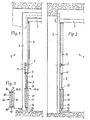
- Figure 3 shows the spring in a completely untensioned state, as it is delivered to the gate before it is hung in the operating position.
- the spring body 11 is already completely encompassed by a sheath 14, which in this example is formed from three sleeves 15, 16, 17, which are connected to one another in the manner of a telescopic tube, as will be explained in greater detail later.
- the covering or the end regions 19 of the sleeves 15 and 17 facing the two spring ends are closed with covers 20 which have a passage opening for the connecting hooks 12, as will also be described in more detail later.
- FIG. 3 shows the spring 10 not used and thus completely untensioned, the spring body 11 of which therefore generally has spring coils which are in contact with one another or are only slightly objected to.
- the spring body 11 is already completely surrounded by the sheath 14.
- the telescopic tube is practically completely pushed together from the sleeves 15 to 17 - FIG. 6.
- the state of the spring, which is only preloaded and slightly stretched during operation, with the gate open correspond, the sheath 14 is drawn a little in length, so that the sleeve 16 is visible next to the sleeve 15.
- the support axis 6 of the double lever 7 is in its lowest position.
- the door leaf is shown closed, the support axis 6 has reached its highest possible position by pivoting the lever 4, whereby the spring 10 is transferred to its highest operational expansion position.
- the spring body 11 is pulled out by pretensioning and operating tension by more than twice its length in the unstretched state, so that the casing has a total of three sleeves.
- the upper hook 12 of the spring 10 can be hooked into a corresponding other receiving opening 9 of the spring receiving band 8, so that the spring preload changes accordingly.
- the connecting hook 9 is hooked into the uppermost receiving opening 9, which corresponds to the greatest possible tension of the spring both in the pretensioned and in the highly tensioned state with the door leaf 3 closed. It can be seen from FIG. 5 that the envelope 14 has its greatest longitudinal extent, that is to say that the sleeves 15-17 are fully extended, as can be seen in FIG.
- the exemplary embodiment of the shielded spring is explained in more detail with reference to FIGS. 6, 7 and 8.
- the very schematic longitudinal sectional view acc. Fig. 6 corresponds to the schematic diagram according to. Fig. 3, ie the spring is completely unstretched, and the spring body 11 is in the state of its smallest possible longitudinal expansion.
- the sleeves 15 to 17 are practically completely pushed into one another, as can be seen in FIG. 6.
- the sleeves are arranged in such a way - FIG. 7 - that their diameter - seen in a longitudinal direction of the telescope - decreases from sleeve to sleeve.
- the end regions 19 of the uppermost sleeve 15 and the lowermost sleeve 17 assigned to the spring ends 18 each have a cover 20 which has a feed-through opening 21 for the associated connection hook 12.
- the cover can be firmly connected to the sleeve, which can be done in various ways, for example by flanging around the correspondingly thickened edge of the end region 19 of the sleeve 15 or 17.
- one of the covers can already be Before using the spring, attach it to the associated end region 19 and then insert the spring, the corresponding hook-shaped extension 12 of which must then be guided through the slot 21.
- the sleeve ends 24 of all sleeves, with the exception of the end regions 19, are provided with projections 25, which are formed, for example, by flanging from the sleeve material and have a hook shape, such that the outlet edge region of the projections 25 formed continuously over the circumference in parallel position the jacket wall 27 of the same sleeve is bent back. This creates an annular groove 28 between this jacket wall 27 and the outlet edge region 26 of the projection 25.
- the projection 25 of the sleeve of smaller diameter is formed radially outwards and the projection 25 of the sleeve of larger diameter is shaped radially inwards. It is thereby achieved that the sleeves pulled apart to the full telescope length engage with the projections in such a way that the outlet edge regions 26 of the one sleeve engage in the annular groove 28 of the other sleeve, as shown in the schematic sectional view according to FIG. Fig. 7 clearly shows.
- the thickened edge of the two end regions 19 for fixing the respectively associated cover 20 by flanging can be designed like the projections 25, in each case protruding radially outwards both with the sleeve 15 and the sleeve 17. During the flanging, the projections 25 deformed to the outer surface 27.
- this is only one example of the definition, which allows the flanging processes for obtaining the projections 25 to be used for the preparatory determination of the cover 20.
- Fig. 8 shows a plan view of the upper lid 20, which in addition to the passage opening 21 for the connecting hook 12 has a through slot 22 which extends perpendicular to the opening 21 and thus forms a cruciform recess together with the latter.
- the feed-through slot 22 serves to allow the lower end of the spring receiving band to engage in the spring body 11 when the connecting hook 12 is hooked into a receiving opening 9 of the spring receiving band located further upward, as shown in FIG. 5.
- FIG. 9 shows a prefabricated spring element with a covering 14 made of two sleeves 15 and 16, which can be telescoped into one another and which are each provided with a cover 20 at opposite ends.
- the sleeves are longer than the completely untensioned spring body 11, namely they are as long as the spring body 11 is in the state of a certain pretension, which corresponds in particular to the lowest tension that occurs during normal operation.
- This design has the advantage that one can use a casing 14 consisting of two sleeves 15 and 16; when the spring is at maximum operating expansion no more than 'double of its length that it occupies in the minimum operating expansion state. In the case of a weight compensation spring for an overhead door considered here, such operating conditions are approximately given.
- the spring is either kept in a prestressed state when the covering is applied and the lids are closed, or the spring is subsequently pulled out of the finished pushed-together covering by a previously attached auxiliary band and fixes in this position.
- this can be done by spacing elements 29 which are inserted between the connecting hooks 12 and the respectively adjacent covers 20.
- a spring delivered in such a way prefabricated is already at least largely in the pre-stressed state, which corresponds to its lowest operating voltage. It can therefore be used in this operating position in a correspondingly light and naturally protected manner.
- the locks 29 are then removed. In this way you get a particularly economical and easy to use, prefabricated spring element.
- the standard prefabrication of the spring with a sheath as a completed component before use in a gate or the like results in simple, mechanical manufacture and safe formation of the sheath, due to good load distribution and positive locking of the sleeve ends 24 to one another with the greatest spring stretch , whereby the sleeves can be dimensioned correspondingly weak and short, so that material and weight are saved.
- the spring can be easily and safely inserted into its preload position. It not only offers protection against finger intervention and spring break damage during operation, but it also protects the mechanic in a corresponding manner when manufacturing the gate or replacing the spring.
Landscapes
- Engineering & Computer Science (AREA)
- Mechanical Engineering (AREA)
- General Engineering & Computer Science (AREA)
- Springs (AREA)
- Mutual Connection Of Rods And Tubes (AREA)
- Holders For Apparel And Elements Relating To Apparel (AREA)
Priority Applications (1)
| Application Number | Priority Date | Filing Date | Title |
|---|---|---|---|
| AT85110990T ATE38872T1 (de) | 1984-09-14 | 1985-08-30 | Abgeschirmte schraubenzugfeder fuer tore oder dergleichen. |
Applications Claiming Priority (4)
| Application Number | Priority Date | Filing Date | Title |
|---|---|---|---|
| DE8427190U | 1984-09-14 | ||
| DE19848427190 DE8427190U1 (de) | 1984-09-14 | 1984-09-14 | Abgeschirmte Schraubenzugfeder für Tore od. dgl. |
| DE8432186U | 1984-11-02 | ||
| DE19848432186 DE8432186U1 (de) | 1984-11-02 | 1984-11-02 | Abgeschirmte Schraubenzugfeder für Tore od. dgl. |
Publications (3)
| Publication Number | Publication Date |
|---|---|
| EP0174573A2 true EP0174573A2 (fr) | 1986-03-19 |
| EP0174573A3 EP0174573A3 (en) | 1987-02-25 |
| EP0174573B1 EP0174573B1 (fr) | 1988-11-23 |
Family
ID=25950034
Family Applications (1)
| Application Number | Title | Priority Date | Filing Date |
|---|---|---|---|
| EP85110990A Expired EP0174573B1 (fr) | 1984-09-14 | 1985-08-30 | Ressort hélicoidal protégé soumis à une force de traction pour portes ou similaires |
Country Status (2)
| Country | Link |
|---|---|
| EP (1) | EP0174573B1 (fr) |
| DE (1) | DE3566427D1 (fr) |
Cited By (2)
| Publication number | Priority date | Publication date | Assignee | Title |
|---|---|---|---|---|
| EP0754830A1 (fr) * | 1995-07-21 | 1997-01-22 | Ets DOITRAND FRERES S.A. | Dispositif de verrouillage en position de portes basculantes à ressort de compensation et d'équilibrage |
| EP1331341A1 (fr) * | 2002-01-29 | 2003-07-30 | Barnes Group, Inc. | Stabilisateur de hayon arrière |
Family Cites Families (1)
| Publication number | Priority date | Publication date | Assignee | Title |
|---|---|---|---|---|
| DE3026612C2 (de) * | 1980-07-14 | 1984-01-19 | Erich 9442 Berneck St. Gallen Döring | Garagenschwingtor mit Federschutz |
-
1985
- 1985-08-30 EP EP85110990A patent/EP0174573B1/fr not_active Expired
- 1985-08-30 DE DE8585110990T patent/DE3566427D1/de not_active Expired
Cited By (3)
| Publication number | Priority date | Publication date | Assignee | Title |
|---|---|---|---|---|
| EP0754830A1 (fr) * | 1995-07-21 | 1997-01-22 | Ets DOITRAND FRERES S.A. | Dispositif de verrouillage en position de portes basculantes à ressort de compensation et d'équilibrage |
| FR2736960A1 (fr) * | 1995-07-21 | 1997-01-24 | Doitrand Freres Sa Ets | Dispositif de verrouillage en position de portes basculantes a ressort de compensation et d'equilibrage |
| EP1331341A1 (fr) * | 2002-01-29 | 2003-07-30 | Barnes Group, Inc. | Stabilisateur de hayon arrière |
Also Published As
| Publication number | Publication date |
|---|---|
| EP0174573A3 (en) | 1987-02-25 |
| EP0174573B1 (fr) | 1988-11-23 |
| DE3566427D1 (en) | 1988-12-29 |
Similar Documents
| Publication | Publication Date | Title |
|---|---|---|
| DE4131098C2 (fr) | ||
| EP0890009B1 (fr) | Porte avec systeme d'equilibrage de poids a ressorts helicoidaux | |
| DE3318681A1 (de) | Stabjalousie | |
| DE19654164C2 (de) | Deckengliedertor | |
| DE202020105223U1 (de) | Rollfeder einer Betätigungsvorrichtung zum Auf-/Zuziehen einer Jalousie | |
| DE3209171A1 (de) | Kraftfahrzeug-fensterheber | |
| EP0726378A1 (fr) | Porte, en particulier porte à sections relevables | |
| EP0174573B1 (fr) | Ressort hélicoidal protégé soumis à une force de traction pour portes ou similaires | |
| DE29614006U1 (de) | Verbindung zwischen Rolladenkasten und Fensterrahmen-Schenkel | |
| DE3440139C2 (de) | Abgeschirmte Schraubenzugfeder für Tore oder dergleichen | |
| EP0097219A2 (fr) | Poignée-barre ou analogue pour véhicules | |
| EP1273755B1 (fr) | Moustiquaire | |
| DE3924947C2 (fr) | ||
| DE8432186U1 (de) | Abgeschirmte Schraubenzugfeder für Tore od. dgl. | |
| DE8427190U1 (de) | Abgeschirmte Schraubenzugfeder für Tore od. dgl. | |
| DE29512889U1 (de) | Sonnenschutz, insbesondere für Kfz-Dachfenster | |
| DE8816593U1 (de) | Jalousiebehang | |
| EP0288061A1 (fr) | Dispositif de montage d'un ressort | |
| DE2658164A1 (de) | Vorrichtung zum ausziehen von mehrfachbuendelleitern | |
| CH695253A5 (de) | Vorrichtung zur Befestigung eines Schwingungsdämpfers an einem Freileitungsseil. | |
| DE69410989T2 (de) | Scharnier für kraftfahrzeug-sonnenblende | |
| DE69410435T2 (de) | Verbessertes Element zur Befestigung von Hebegurten von Rolläden | |
| EP4497907B1 (fr) | Échelle et procédé de fabrication d'une échelle | |
| DE2732915A1 (de) | Tor- bzw. tueranordnung | |
| EP1336717A2 (fr) | Porte enroulable |
Legal Events
| Date | Code | Title | Description |
|---|---|---|---|
| PUAI | Public reference made under article 153(3) epc to a published international application that has entered the european phase |
Free format text: ORIGINAL CODE: 0009012 |
|
| AK | Designated contracting states |
Kind code of ref document: A2 Designated state(s): AT BE CH DE FR GB IT LI LU NL SE |
|
| RBV | Designated contracting states (corrected) |
Designated state(s): AT BE CH DE FR GB IT LI NL SE |
|
| PUAL | Search report despatched |
Free format text: ORIGINAL CODE: 0009013 |
|
| AK | Designated contracting states |
Kind code of ref document: A3 Designated state(s): AT BE CH DE FR GB IT LI NL SE |
|
| 17P | Request for examination filed |
Effective date: 19870427 |
|
| 17Q | First examination report despatched |
Effective date: 19880428 |
|
| GRAA | (expected) grant |
Free format text: ORIGINAL CODE: 0009210 |
|
| AK | Designated contracting states |
Kind code of ref document: B1 Designated state(s): AT BE CH DE FR GB IT LI NL SE |
|
| REF | Corresponds to: |
Ref document number: 38872 Country of ref document: AT Date of ref document: 19881215 Kind code of ref document: T |
|
| REF | Corresponds to: |
Ref document number: 3566427 Country of ref document: DE Date of ref document: 19881229 |
|
| ET | Fr: translation filed | ||
| ITF | It: translation for a ep patent filed | ||
| GBT | Gb: translation of ep patent filed (gb section 77(6)(a)/1977) | ||
| PLBE | No opposition filed within time limit |
Free format text: ORIGINAL CODE: 0009261 |
|
| STAA | Information on the status of an ep patent application or granted ep patent |
Free format text: STATUS: NO OPPOSITION FILED WITHIN TIME LIMIT |
|
| 26N | No opposition filed | ||
| ITTA | It: last paid annual fee | ||
| EAL | Se: european patent in force in sweden |
Ref document number: 85110990.0 |
|
| PGFP | Annual fee paid to national office [announced via postgrant information from national office to epo] |
Ref country code: SE Payment date: 19980709 Year of fee payment: 14 |
|
| PGFP | Annual fee paid to national office [announced via postgrant information from national office to epo] |
Ref country code: BE Payment date: 19980710 Year of fee payment: 14 |
|
| PGFP | Annual fee paid to national office [announced via postgrant information from national office to epo] |
Ref country code: AT Payment date: 19980803 Year of fee payment: 14 |
|
| PGFP | Annual fee paid to national office [announced via postgrant information from national office to epo] |
Ref country code: CH Payment date: 19980807 Year of fee payment: 14 |
|
| PGFP | Annual fee paid to national office [announced via postgrant information from national office to epo] |
Ref country code: NL Payment date: 19980817 Year of fee payment: 14 |
|
| PGFP | Annual fee paid to national office [announced via postgrant information from national office to epo] |
Ref country code: GB Payment date: 19980818 Year of fee payment: 14 |
|
| PGFP | Annual fee paid to national office [announced via postgrant information from national office to epo] |
Ref country code: FR Payment date: 19980828 Year of fee payment: 14 |
|
| PGFP | Annual fee paid to national office [announced via postgrant information from national office to epo] |
Ref country code: DE Payment date: 19981030 Year of fee payment: 14 |
|
| PG25 | Lapsed in a contracting state [announced via postgrant information from national office to epo] |
Ref country code: GB Free format text: LAPSE BECAUSE OF NON-PAYMENT OF DUE FEES Effective date: 19990830 Ref country code: AT Free format text: LAPSE BECAUSE OF NON-PAYMENT OF DUE FEES Effective date: 19990830 |
|
| PG25 | Lapsed in a contracting state [announced via postgrant information from national office to epo] |
Ref country code: SE Free format text: THE PATENT HAS BEEN ANNULLED BY A DECISION OF A NATIONAL AUTHORITY Effective date: 19990831 Ref country code: LI Free format text: LAPSE BECAUSE OF NON-PAYMENT OF DUE FEES Effective date: 19990831 Ref country code: CH Free format text: LAPSE BECAUSE OF NON-PAYMENT OF DUE FEES Effective date: 19990831 Ref country code: BE Free format text: LAPSE BECAUSE OF NON-PAYMENT OF DUE FEES Effective date: 19990831 |
|
| BERE | Be: lapsed |
Owner name: HORMANN K.G. AMSHAUSEN Effective date: 19990831 |
|
| PG25 | Lapsed in a contracting state [announced via postgrant information from national office to epo] |
Ref country code: NL Free format text: LAPSE BECAUSE OF NON-PAYMENT OF DUE FEES Effective date: 20000301 |
|
| REG | Reference to a national code |
Ref country code: CH Ref legal event code: PL |
|
| GBPC | Gb: european patent ceased through non-payment of renewal fee |
Effective date: 19990830 |
|
| PG25 | Lapsed in a contracting state [announced via postgrant information from national office to epo] |
Ref country code: FR Free format text: LAPSE BECAUSE OF NON-PAYMENT OF DUE FEES Effective date: 20000428 |
|
| EUG | Se: european patent has lapsed |
Ref document number: 85110990.0 |
|
| NLV4 | Nl: lapsed or anulled due to non-payment of the annual fee |
Effective date: 20000301 |
|
| PG25 | Lapsed in a contracting state [announced via postgrant information from national office to epo] |
Ref country code: DE Free format text: LAPSE BECAUSE OF NON-PAYMENT OF DUE FEES Effective date: 20000601 |
|
| REG | Reference to a national code |
Ref country code: FR Ref legal event code: ST |