EP0174758A2 - Sprüharm sowie Verfahren und Vorrichtung zur Herstellung desselben - Google Patents
Sprüharm sowie Verfahren und Vorrichtung zur Herstellung desselben Download PDFInfo
- Publication number
- EP0174758A2 EP0174758A2 EP85305974A EP85305974A EP0174758A2 EP 0174758 A2 EP0174758 A2 EP 0174758A2 EP 85305974 A EP85305974 A EP 85305974A EP 85305974 A EP85305974 A EP 85305974A EP 0174758 A2 EP0174758 A2 EP 0174758A2
- Authority
- EP
- European Patent Office
- Prior art keywords
- tubing
- holes
- wedge
- along
- hole
- Prior art date
- Legal status (The legal status is an assumption and is not a legal conclusion. Google has not performed a legal analysis and makes no representation as to the accuracy of the status listed.)
- Granted
Links
Images



Classifications
-
- B—PERFORMING OPERATIONS; TRANSPORTING
- B05—SPRAYING OR ATOMISING IN GENERAL; APPLYING FLUENT MATERIALS TO SURFACES, IN GENERAL
- B05B—SPRAYING APPARATUS; ATOMISING APPARATUS; NOZZLES
- B05B1/00—Nozzles, spray heads or other outlets, with or without auxiliary devices such as valves, heating means
- B05B1/14—Nozzles, spray heads or other outlets, with or without auxiliary devices such as valves, heating means with multiple outlet openings; with strainers in or outside the outlet opening
- B05B1/20—Perforated pipes or troughs, e.g. spray booms; Outlet elements therefor
-
- A—HUMAN NECESSITIES
- A47—FURNITURE; DOMESTIC ARTICLES OR APPLIANCES; COFFEE MILLS; SPICE MILLS; SUCTION CLEANERS IN GENERAL
- A47L—DOMESTIC WASHING OR CLEANING; SUCTION CLEANERS IN GENERAL
- A47L15/00—Washing or rinsing machines for crockery or tableware
- A47L15/42—Details
-
- B—PERFORMING OPERATIONS; TRANSPORTING
- B21—MECHANICAL METAL-WORKING WITHOUT ESSENTIALLY REMOVING MATERIAL; PUNCHING METAL
- B21D—WORKING OR PROCESSING OF SHEET METAL OR METAL TUBES, RODS OR PROFILES WITHOUT ESSENTIALLY REMOVING MATERIAL; PUNCHING METAL
- B21D28/00—Shaping by press-cutting; Perforating
- B21D28/24—Perforating, i.e. punching holes
- B21D28/28—Perforating, i.e. punching holes in tubes or other hollow bodies
-
- Y—GENERAL TAGGING OF NEW TECHNOLOGICAL DEVELOPMENTS; GENERAL TAGGING OF CROSS-SECTIONAL TECHNOLOGIES SPANNING OVER SEVERAL SECTIONS OF THE IPC; TECHNICAL SUBJECTS COVERED BY FORMER USPC CROSS-REFERENCE ART COLLECTIONS [XRACs] AND DIGESTS
- Y10—TECHNICAL SUBJECTS COVERED BY FORMER USPC
- Y10S—TECHNICAL SUBJECTS COVERED BY FORMER USPC CROSS-REFERENCE ART COLLECTIONS [XRACs] AND DIGESTS
- Y10S239/00—Fluid sprinkling, spraying, and diffusing
- Y10S239/01—Pattern sprinkler
-
- Y—GENERAL TAGGING OF NEW TECHNOLOGICAL DEVELOPMENTS; GENERAL TAGGING OF CROSS-SECTIONAL TECHNOLOGIES SPANNING OVER SEVERAL SECTIONS OF THE IPC; TECHNICAL SUBJECTS COVERED BY FORMER USPC CROSS-REFERENCE ART COLLECTIONS [XRACs] AND DIGESTS
- Y10—TECHNICAL SUBJECTS COVERED BY FORMER USPC
- Y10S—TECHNICAL SUBJECTS COVERED BY FORMER USPC CROSS-REFERENCE ART COLLECTIONS [XRACs] AND DIGESTS
- Y10S29/00—Metal working
- Y10S29/026—Method or apparatus with machining
-
- Y—GENERAL TAGGING OF NEW TECHNOLOGICAL DEVELOPMENTS; GENERAL TAGGING OF CROSS-SECTIONAL TECHNOLOGIES SPANNING OVER SEVERAL SECTIONS OF THE IPC; TECHNICAL SUBJECTS COVERED BY FORMER USPC CROSS-REFERENCE ART COLLECTIONS [XRACs] AND DIGESTS
- Y10—TECHNICAL SUBJECTS COVERED BY FORMER USPC
- Y10T—TECHNICAL SUBJECTS COVERED BY FORMER US CLASSIFICATION
- Y10T29/00—Metal working
- Y10T29/49—Method of mechanical manufacture
- Y10T29/49428—Gas and water specific plumbing component making
- Y10T29/49432—Nozzle making
- Y10T29/49433—Sprayer
Definitions
- the present invention relates generally to the formation of spray nozzles along a fluid conduit, and more particularly, to a wash arm for a dishwashing machine and a method and apparatus for forming the same.
- Virtually all dishwashers whether commercial or domestic, operate by directing pressurized streams of heated washing liquid consisting of water and detergent against the ware to be washed.
- the heated water sanitizes the ware, while the pressurized streams strip soil particles from the ware.
- These streams typically emanate from a plurality of nozzles which are formed along one or more fluid conduits or wash arms.
- a pumping system directs water into the wash arm, and the water then exits through the nozzles for cleansing of the ware. In order to properly clean the ware, complete coverage is required.
- a number of different nozzle constructions have been used in dishwashing machines, along with a range of methods for forming the nozzles.
- such variety has been caused by the variety in types of dishwashing machines, in which different needs in terms of nozzle performance are typically present.
- wash arm and nozzle construction can be seen in U. S. Patent No. 4,439,242 issued March 27, 1984 to Hadden.
- One type of wash arm is shown for use in a commercial dishwasher designed to wash only a single rack of ware at any one time.
- Upper and lower wash arm assemblies are provided, each comprising a pair of fluid conduits extending in opposite directions from a central hub.
- Each conduit has several bosses formed along its length, directed generally toward the interior of the wash chamber.
- a slot is formed on each boss to extend in a direction parallel to the conduit.
- the bosses are formed to direct water from the slots in a somewhat rearward direction with respect to the desired direction of rotation of the arm about the central hub.
- the water pressure as the water emerges from each slot also causes rotation of the arms.
- the Hadden patent also discloses a conveyor-type commercial dishwasher in a which a different wash arm construction is used.
- a plurality of arms are disposed above and below the conveyor path, extending generally laterally across each rack of dishes as it is moved through the machine. Because the arms are stationary, more precise direction of the water streams emerging from each nozzle is required to achieve adequate coverage.
- a fan-like structure is attached to the exterior surface of each conduit, with a slot formed through the conduit and opening into the interior of the structure.
- Each wash arm is formed from trough-like upper and lower half portions, which are subsequently attached by crimping along the side edges of the half portions to form the entire arm.
- Formed within one half portion of the arm are a series of spherical inward impressions, each having a slot defined therein through the portion. The impressions and slots define the nozzles along the wash arm, and are formed at the same time as the half portion is initially fabicated by stamping the halves from sheet material.
- the inward impressions formed in the wash arms substantially solve the problem associated with outward bosses, in that soil particles do not collect around the nozzle area.
- the stamping procedure requires a significant investment in tooling, as does the machinery for crimping the halves to form the completed wash arm. This increases the cost of manufacturing for each dishwasher, and is a particularly significant problem for large commercial type dishwashing machines, such as those shown in the Hadden patent. Since relatively small numbers of such machines are manufactured, the relatively expensive tooling to form such wash arms repesents an economic drawback.
- a wash arm formed by such a method should tend to resist clogging of nozzle openings by soil particles, and should be capable of producing relatively well-defined and accurately positioned water streams. This will enable such an arm to be used in a variety of types of machines.
- the present invention meets these needs by providing a method of forming spray nozzles along a fluid conduit, the conduit then being suitable for use within a dishwashing machine as a wash arm.
- a hole is drilled into a length of tubing so that the hole defines an opening substantially radial to the central axis of the tubing.
- the hole is then countersunk to the bottom of the hole, whereby the opening is of a greater diameter on the outer surface of the tubing than on the inner surface.
- a portion of the tubing is then depressed inwardly along an imaginary line parallel to the central tube axis that extends along the outer surface of the tubing.
- the line passes over the hole, so that the depression and hole together form a spray nozzle that will direct a fairly narrow-width, fan-shaped water stream outwardly from the tubing when the tubing is pressurized with water.
- the method may include the drilling, countersinking and deburring of a hole, followed by supporting the tubing around substantially its entire outer surface.
- a wedge having a leading edge is positioned against the outer surface of the tubing along the line parallel to the central tube axis and over the hole. The wedge is directed towards the axis, and is then forced radially aqainst the tubing, whereby the outer surface along the line is moved inwardly toward the central tube axis.
- a plurality of holes may be formed along the tubing to provide a wash arm having a plurality of spray nozzles which provide overlapped fan-shaped sprays to form a continuous wall of water along the tubing.
- the holes are formed along the tubing in a substantially linear relationship parallel to the central tube axis. To acheive non-interference from adjacent sprays, the holes are formed in an alternately staggered fashion with respect to an imaginary line parallel to the central tube axis.
- Individual depressions are preferably formed for each hole, although a single depression might be formed along substantially the entire tubing. In any event, the depressions are formed along the line passing over the holes.
- the present invention also provides an apparatus for forming a spray nozzle into a length of ductile tubing.
- the tubing is provided with a hole formed therethrough substantially radial to the central tube axis, countersunk so that the hole is of greater diameter on the outer surface than on the inner surface of the tubing.
- the apparatus includes means for releasably supporting the tubing around substantially the entire portion of its outer surface, and a wedge having a leading edge.
- the wedge is slidably carried within an opening through the supporting means so that the leading edge can be positioned against the outer surface of the tubing when held within the supporting means, and is disposed adjacent the outer surface to extend over each hole. Relative movement of the wedge with respect to the supporting means causes the wedge to depress inwardly the portion of the tubing adjacent the wedge.
- the method according to the present invention for forming a series of spray nozzles along a fluid conduit produces a wash arm that is suitable for use within a dishwashing machine.
- the completed wash arm can be used with several different types of such machines, and essentially is simply substituted for wash arms presently employed, whether they be stationary or rotatable. Specific examples of two typical dishwashing machines with which the wash arms can be used are found in U. S. Patent No. 4,439,242, issued March 27, 1984 to Hadden, which is hereby incorporated by reference.
- One such machine disclosed therein is a conveyor-type machine, where racks of ware to be washed are moved along a conveyor to various stations within the machine at which washing, rinsing, drying and the like are performed.
- a second type disclosed therein is a single rack machine, in which a single rack of ware is placed into the machine, with all of the washing steps being carried out at a single location.
- wash arms formed according to the present method could be used in a domestic, home-type dishwasher.
- the present method may be used to form spray nozzles along a fluid conduit for uses other than in a dishwashing machine.
- the present invention is well suited for forming wash arms, the ultimate end use of the fluid conduit with spray nozzles formed by the present invention should in no way be taken to limit the scope of the present invention.
- the method of the present invention is performed upon a length of cylindrical tubing, from which the fluid conduit and spray nozzles therein are formed.
- the tubing is of a ductile material and in the preferred embodiment, for use as a dishwasher wash arm, is stainless steel tubing having a diameter of 3.75 cm and a wall thickness of 0.125 cm.
- the tubing may be formed from some other metallic or even non-metallic ductile material.
- the length of the tubing is entirely dependent upon its intended use.
- the length of tubing 10 has a series of holes 12 formed, preferably by drilling, through the wall of tubing 10. Holes 12 are all drilled generally along an imaginary line 14 on the outer surface of tubing 10 that is parallel to the central axis of the tubing. For reasons that will be described in detail below, the holes may be drilled along line 14 in an alternating staggered fashion so as to be slightly off-center from line 14. The axis of each hole 12 extends radially toward the center of tubing 10, and in the preferred embodiment, each hole 12 is of a diameter of 0.625 cm. Further, adjacent holes are separated by 13.0 cm center-to-center.
- each hole 12 is countersunk to the boe7m of the hole as shown in Figs. 2 and 3.
- an approximately 82° countersink is provided.
- each hole 12 includes a beveled side 16.
- Drilling normally creates burrs on the inner edges of the holes 12 as shown in Figs. 1 and 3. While countersinking often removes some of the burrs, any burrs remaining after countersinking should be removed by any standard deburring tool. If not removed, the burrs create the potential for catching soil when the completed tubing is subsequently used, possibly blocking passage of fluid.
- Apparatus 20 is mounted within a typical ram press, and includes punch tooling 30 having a punch 32 secured to an upper base 34. Upper base 34 is in turn connected to the press ram (not shown) so that punch tooling 30 can be moved up and down by the ram.
- Punch 32 is provided with a half-cylindrical trough 36 having a radius equal to the outer radius of tubing 10, and a length slightly less than tubing 10.
- Die tooling 40 is carried on the press bed, and is supported by lower base 42.
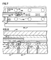
- a bottom plate 44 is mounted to lower base 42 and includes a plurality of springs 46 (one shown; see also Fig. 7) carried in bottom plate 44 for supporting die 48.
- Die 48 includes a half-cylindrical trough 50 formed therein having a radius equal to the outer radius of tubing 10. Thus, when die 48 and punch 32 are placed together, troughs 36 and 50 cooperate to form a cylindrical chamber of identical diameter to tubing 10.
- An opening 52 is provided at the bottom of trough 50.
- a wedge 54 is carried within opening 52, secured to bottom plate 44 by a bolt 56.
- Additional bolts 58 (only one shown for clarity; see Fig. 7 for proper positioning) pass through openings in die 48 and are secured into bottom plate 44.
- the head 60 of each bolt 58 serves as an upward limit on movement of die 48 by spxings 46.
- a pair of guide plates 62 are secured to either or both lower base 42 and bottom plate 44, to insure that any movement of die 48 with respect to bottom plate 44 is entirely within a vertical direction.
- a stop 64 is carried on lower base 42 to provide a limit to downward movement of punch tooling 30.
- tubing 10 is placed into trough 50 of die 48.
- Tubing 10 is placed within trough 50 so that holes 12 are at the lowermost portion of tubing 10, and are positioned directly above leading edge 66 on wedge 54.
- Axial and circumferential location of the tubing is controlled by a positioning pin 70 as will be later described in connection with Figs. 7 and 8.
- die tooling 30 continues to be moved downward, and punch 32, having contacted die 48, forces die 48 downwardly toward bottom plate 44. Since wedge 54 is secured against bottom plate 44, it moves through opening 52 in trough 50, emerging thereinto. Wedge 54 contacts tubing 10, and depresses the portion of tubing 10 adjacent wedge 54 inwardly. Thus, a depression is formed into, tubing 10, with holes 12 positioned along the base of the depression. Because tubing 10 is fully supported elsewhere about its exterior, only that portion adjacent wedge 54 is deformed. No internal mandrel is required to support the inner surface of the deformed tubing.
- punch tooling 30 has been lowered so that upper base 34 contacts stop 64, downward motion is halted and formation of tubing 10 is substantially completed.
- Punch tooling 30 is then raised, releasing die tooling 40, with die 48 being raised from bottom plate 44 by springs 46.
- the tooling 20 is then returned to its initial position shown in Fig. 4.
- a series of individual wedges 54 one for each nozzle to be formed, are provided.
- individual depressions are formed for each hole 12 along tubing 10.
- a single elongated wedge could be used to form a single depression into tubing 10 extending substantially along its entire length. In such a case, if the depression is permitted to extend fully to the ends of tubing 10, an internal mandrel could be used as part of the forming tooling. Complete external support of tubing 10 then might not be needed.
- springs 46 are positioned in pairs on opposite sides of the trough 50 formed within die 48.
- the bolts 58 for limiting upward movement of die 48 by springs 46 are disposed near the four corners of die 48.
- FIGs. 7 and 8 it will be noted from Figs. 7 and 8 that during the forming of holes 12 into tubing 10, an additional hole 68 is provided along the same line on which holes 12 are formed.
- hole 68 engages with a pin 70 secured within trough 50 of die 48.
- tubing 10 can be accurately positioned within die 48 so that holes 12 will be properly located above the leading edges 66 of wedges 54.
- hole 68 can be filled or plugged, or that portion of tubing 10 containing hole 68 can be cut off.
- tubing 10 extends beyond punch 32 and die 48 when positioned within apparatus 20.
- tubing 10 can be placed into or removed from apparatus 20 by an operator or by appropriate machinery without placement of anything other than tubing 10 into the working area of apparatus 20.
- tubing 10 into a fluid conduit having a plurality of spray nozzles, such as might be used in a dishwashing machine, is essentially complete. It may be necessary to trim the ends of tubing 10 to achieve the proper length for the fluid conduit, and/or end fittings or threaded portions may be welded onto the ends of the tubing to facilitate installment of the conduit into a dishwashing machine or other apparatus in which it is to be used. While such steps may be necessary to facilitate installation of the conduit, it is to be understood that such additional steps are not regarded as forming a part of the method of the present invention.
- a series of depressions 72 and 74 are formed into tubing 10, with a hole 76 and 78, respectively, positioned at the center and bottom of each depression 72 and 74.
- the inward depression of the tubing 10 during formation of the spray nozzles is carried out to a depth into the tubing that partially distorts each of the holes 76 and 78 to be of essentially equal or greater diameter on the inner .surface of the tubing than on the outer surface.
- This distortion occurs, however, only at right angles to the imaginary line 14 along which the holes were formed, so that along line 14, each hole continues to be of greater diameter on the outer tubing surface.
- This directional distortion results in the finished nozzles producing the spray patterns described above.
- Spray nozzles formed by the method of the present invention can therefore be provided sufficiently close together to insure adequate spray coverage, without any interference with the velocity or direction of the water stream emerging from each nozzle. In a dishwasher, this results in effectively a solid, relatively thin wall of water being directed from the tubing 10 to the ware.
Landscapes
- Engineering & Computer Science (AREA)
- Mechanical Engineering (AREA)
- Cleaning By Liquid Or Steam (AREA)
- Nozzles (AREA)
Applications Claiming Priority (2)
| Application Number | Priority Date | Filing Date | Title |
|---|---|---|---|
| US649586 | 1984-09-12 | ||
| US06/649,586 US4582259A (en) | 1984-09-12 | 1984-09-12 | Wash arm and method and apparatus for forming the same |
Publications (3)
| Publication Number | Publication Date |
|---|---|
| EP0174758A2 true EP0174758A2 (de) | 1986-03-19 |
| EP0174758A3 EP0174758A3 (en) | 1988-07-20 |
| EP0174758B1 EP0174758B1 (de) | 1991-04-24 |
Family
ID=24605444
Family Applications (1)
| Application Number | Title | Priority Date | Filing Date |
|---|---|---|---|
| EP85305974A Expired - Lifetime EP0174758B1 (de) | 1984-09-12 | 1985-08-22 | Sprüharm sowie Verfahren und Vorrichtung zur Herstellung desselben |
Country Status (4)
| Country | Link |
|---|---|
| US (1) | US4582259A (de) |
| EP (1) | EP0174758B1 (de) |
| CA (1) | CA1258027A (de) |
| DE (1) | DE3582637D1 (de) |
Cited By (10)
| Publication number | Priority date | Publication date | Assignee | Title |
|---|---|---|---|---|
| EP0253605B1 (de) * | 1986-07-14 | 1992-05-13 | Albany International Corp. | Spritzrohr |
| WO1996028263A1 (en) * | 1995-03-10 | 1996-09-19 | Unilever N.V. | Spray pipe system |
| GB2325753A (en) * | 1997-05-22 | 1998-12-02 | Adams Hydraulics Limited | Control of fluid flows from manifolds and side weirs |
| EP0832693A3 (de) * | 1996-09-27 | 1998-12-09 | Maitron Chemiefreie Wasserbehandlung G.M.B.H. | Wassersprenger |
| DE10323356A1 (de) * | 2003-05-21 | 2004-12-09 | Kretzschmar, Axel, Dr.Rer.Nat.Habil. | Anordnung zur Erzeugung ebener Sprühfelder |
| DE102005015156A1 (de) * | 2005-04-02 | 2006-10-05 | Premark Feg L.L.C., Wilmington | Transportgeschirrspülmaschine und Sprührohr dafür |
| EP1698404A4 (de) * | 2003-12-26 | 2012-05-16 | Aion Co Ltd | Kern zum waschen einer schwammrolle |
| US8561924B2 (en) | 2007-03-16 | 2013-10-22 | Rolls-Royce Plc | Cooling arrangement |
| EP2719477A3 (de) * | 2012-10-10 | 2016-09-07 | Milan Kubin | Vorrichtung zum Umformen von Wärmetauscherrohre |
| WO2019022677A1 (en) * | 2017-07-26 | 2019-01-31 | Brinox D.O.O. | ROTOR FOR CLEANING MACHINE |
Families Citing this family (27)
| Publication number | Priority date | Publication date | Assignee | Title |
|---|---|---|---|---|
| US5022151A (en) * | 1989-01-25 | 1991-06-11 | Baumac International | Method of making an aerosol nozzle assembly |
| US5154356A (en) * | 1990-01-19 | 1992-10-13 | Baumac International | Aerosol nozzle assembly and method of making the same |
| US5536100A (en) * | 1992-12-29 | 1996-07-16 | Ran Enterprises, Inc. | Mechanically joined tubular connection and process to form same |
| US5312198A (en) * | 1992-12-29 | 1994-05-17 | Ran Enterprises, Inc. | Jack extension tube |
| FR2746041B1 (fr) * | 1996-03-18 | 1998-05-29 | Procede de realisation d'une forme dans une paroi metallique et electrode pour la mise en oeuvre de ce procede | |
| DE19733473C2 (de) * | 1997-08-02 | 2000-07-06 | Daimler Chrysler Ag | Verfahren und Vorrichtung zur Herstellung einer Anbindung eines lambda-Sondenhalters an ein Abgasrohr |
| EP0974409B1 (de) * | 1998-07-21 | 2001-11-14 | Etablissements Garconnet | Verfahren zum Herstellen von Rastnuten in Rohren, sowie durch das Verfahren hergestellten Rohre |
| DE19941993C1 (de) * | 1999-09-02 | 2000-12-14 | Benteler Werke Ag | Verfahren zur Herstellung eines biegesteifen torsionsweichen Rohrprofils als Querträger für eine Verbundlenkerhinterachse eines Personenkraftwagens |
| JP2001239340A (ja) * | 2000-02-29 | 2001-09-04 | Aisin Seiki Co Ltd | 支持棒およびその製造方法 |
| US6418961B1 (en) | 2000-04-18 | 2002-07-16 | Edstrom Industries, Inc. | Water supply manifold |
| FR2816857B1 (fr) * | 2000-11-20 | 2003-02-28 | Faurecia Sieges Automobile | Procede et dispositif de crantage d'un tube d'armature pour un siege de vehicule automobile, notamment un tube d'armature d'appuie-tete |
| WO2003013905A2 (en) * | 2001-08-01 | 2003-02-20 | Intier Automotive Inc. | Structrural head restraint guide |
| FR2832943B1 (fr) * | 2001-12-04 | 2004-03-12 | Ressorts Lefevere | Procede, dispositif pour le crantage de tubes et tube obtenu par la mise en oeuvre du procede |
| DE10238557A1 (de) * | 2002-08-22 | 2004-03-04 | BSH Bosch und Siemens Hausgeräte GmbH | Verfahren und Vorrichtung zum Herstellen von düsenartigen Ausbrüchen in Sprüharmen für Geschirrspülmaschinen |
| DE102004030004A1 (de) * | 2004-06-22 | 2006-01-12 | Premark Feg L.L.C. (N.D.Ges.D. Staates Delaware), Wilmington | Sprühdüse für eine Geschirrspülmaschine |
| DE102004030003A1 (de) | 2004-06-22 | 2006-01-12 | Premark Feg L.L.C. (N.D.Ges.D. Staates Delaware), Wilmington | Spülmaschinen-Betriebsverfahren und Transportspülmaschine |
| FR2873190B1 (fr) * | 2004-07-15 | 2015-02-20 | E G O Production | Brise-jet, notamment pour chauffe-eau |
| US20060059683A1 (en) * | 2004-07-19 | 2006-03-23 | Catalogna John A | Draw-form for exhaust components and method of manufacture |
| US8118242B2 (en) * | 2007-01-24 | 2012-02-21 | Illinois Tool Works Inc. | Wash arm retainer for warewasher |
| US7938339B2 (en) * | 2007-11-02 | 2011-05-10 | Steris Inc. | Nozzle assembly for a washer |
| US8720929B2 (en) * | 2011-09-23 | 2014-05-13 | Specialized Bicycle Components, Inc. | Bicycle frame |
| FR2991893B1 (fr) * | 2012-06-15 | 2015-01-02 | Numalliance | Procede de crantage de tube, et machine de crantage associee |
| US10750924B2 (en) * | 2016-03-24 | 2020-08-25 | Whirlpool Corporation | Dishwasher with tube wash system |
| CN106270149A (zh) * | 2016-08-30 | 2017-01-04 | 广西塔锡科技有限公司 | 一种加工通孔的方法 |
| TWI674932B (zh) | 2018-10-08 | 2019-10-21 | 品岳科技股份有限公司 | 管件加工孔強化結構 |
| DE102019120818A1 (de) * | 2019-08-01 | 2021-02-04 | Voith Patent Gmbh | Reinigungssystem und Saugwalze |
| CA3165959A1 (en) * | 2021-06-29 | 2022-12-29 | Ail International Inc. | Apparatus for producing hollow panels and method of operating same |
Family Cites Families (13)
| Publication number | Priority date | Publication date | Assignee | Title |
|---|---|---|---|---|
| US528144A (en) * | 1894-10-30 | Combined fountain and sprinkler | ||
| US978597A (en) * | 1909-06-26 | 1910-12-13 | Patrick W Sweeney | Sprinkling-pipe. |
| US1410312A (en) * | 1920-03-16 | 1922-03-21 | Huffman Mike | Steam-boiler clean-out device |
| US2744429A (en) * | 1952-06-18 | 1956-05-08 | John S Seely | Tool for and method of forming a flow restriction in a conduit |
| US2714277A (en) * | 1952-12-06 | 1955-08-02 | Walter B Moore | Deburring or polishing machine |
| GB835251A (en) * | 1955-03-14 | 1960-05-18 | Vits Elektro G M B H | Blower nozzles for driers of web-like material |
| US2905393A (en) * | 1958-03-14 | 1959-09-22 | George J Federighi | Rotary spray arm for a cleaning machine |
| US3209575A (en) * | 1962-04-30 | 1965-10-05 | Jr Bernard Woodward | Apparatus for deforming tubular material |
| DE1182785B (de) * | 1962-05-23 | 1964-12-03 | Linde Eismasch Ag | Spuelmaschine, insbesondere fuer Geschirr |
| US3288372A (en) * | 1964-08-27 | 1966-11-29 | Gen Electric | Non-clogging dishwasher arm orifices forming a fan-like vena contracta spray pattern |
| US3323529A (en) * | 1965-07-26 | 1967-06-06 | Hobart Mfg Co | Liquid distributing system for dishwashing machine |
| US3430861A (en) * | 1965-07-26 | 1969-03-04 | Hobart Corp | Liquid distributing system for dishwashing machine |
| US4439242A (en) * | 1980-05-15 | 1984-03-27 | Hobart Corporation | Low hot water volume warewasher |
-
1984
- 1984-09-12 US US06/649,586 patent/US4582259A/en not_active Expired - Lifetime
-
1985
- 1985-08-14 CA CA000488687A patent/CA1258027A/en not_active Expired
- 1985-08-22 EP EP85305974A patent/EP0174758B1/de not_active Expired - Lifetime
- 1985-08-22 DE DE8585305974T patent/DE3582637D1/de not_active Expired - Fee Related
Cited By (13)
| Publication number | Priority date | Publication date | Assignee | Title |
|---|---|---|---|---|
| EP0253605B1 (de) * | 1986-07-14 | 1992-05-13 | Albany International Corp. | Spritzrohr |
| WO1996028263A1 (en) * | 1995-03-10 | 1996-09-19 | Unilever N.V. | Spray pipe system |
| EP0832693A3 (de) * | 1996-09-27 | 1998-12-09 | Maitron Chemiefreie Wasserbehandlung G.M.B.H. | Wassersprenger |
| GB2325753A (en) * | 1997-05-22 | 1998-12-02 | Adams Hydraulics Limited | Control of fluid flows from manifolds and side weirs |
| GB2325753B (en) * | 1997-05-22 | 2001-01-31 | Adams Hydraulics Ltd | Control of fluid flows from manifolds and side weirs |
| DE10323356A1 (de) * | 2003-05-21 | 2004-12-09 | Kretzschmar, Axel, Dr.Rer.Nat.Habil. | Anordnung zur Erzeugung ebener Sprühfelder |
| EP1698404A4 (de) * | 2003-12-26 | 2012-05-16 | Aion Co Ltd | Kern zum waschen einer schwammrolle |
| DE102005015156A1 (de) * | 2005-04-02 | 2006-10-05 | Premark Feg L.L.C., Wilmington | Transportgeschirrspülmaschine und Sprührohr dafür |
| US7621286B2 (en) | 2005-04-02 | 2009-11-24 | Premark Feg L.L.C. | Conveyor ware washer and spray pipe therefor |
| US8561924B2 (en) | 2007-03-16 | 2013-10-22 | Rolls-Royce Plc | Cooling arrangement |
| EP2719477A3 (de) * | 2012-10-10 | 2016-09-07 | Milan Kubin | Vorrichtung zum Umformen von Wärmetauscherrohre |
| WO2019022677A1 (en) * | 2017-07-26 | 2019-01-31 | Brinox D.O.O. | ROTOR FOR CLEANING MACHINE |
| US11684233B2 (en) | 2017-07-26 | 2023-06-27 | Brinox D.O.O. | Rotor for a cleaning machine |
Also Published As
| Publication number | Publication date |
|---|---|
| US4582259A (en) | 1986-04-15 |
| EP0174758A3 (en) | 1988-07-20 |
| CA1258027A (en) | 1989-08-01 |
| DE3582637D1 (de) | 1991-05-29 |
| EP0174758B1 (de) | 1991-04-24 |
Similar Documents
| Publication | Publication Date | Title |
|---|---|---|
| US4582259A (en) | Wash arm and method and apparatus for forming the same | |
| US5546968A (en) | Supplementary washing device of a dish washer | |
| US5945196A (en) | Method of manufacturing screen and films produced therewith | |
| DE3600716A1 (de) | Reinigungsverfahren und -vorrichtung zur durchfuehrung desselben | |
| US5683210A (en) | Machine tool chip flushing apparatus and method | |
| EP0616099A1 (de) | Schwimmbadreinigungskreisplatte | |
| CN211990602U (zh) | 一种用于冲压设备的润滑装置 | |
| WO2001072409A1 (de) | Bodenelement für eine vorrichtung zum behandeln von partikelförmigem gut | |
| US3292775A (en) | Track for vibratory conveyors | |
| CA2038139C (en) | Multiple stage shaving die | |
| EP0253605B1 (de) | Spritzrohr | |
| JPH0691590A (ja) | シート材の切断装置、その切断方法、及び環状カッティング・ディスクの製造方法 | |
| CN206392737U (zh) | 一种加工热水器法兰盘用自动化输料冲压系统 | |
| RU2046685C1 (ru) | Способ а.н.алексеева для изготовления изделия с отверстиями методом литья | |
| CN212310292U (zh) | 一种用于工件冷却除水除残渣的回收装置 | |
| DE19857647A1 (de) | Waschmittel-Einspülvorrichtung | |
| CN117428071A (zh) | 一种空调压缩机中间板冲压装置 | |
| CN112007996A (zh) | 一种用于冲压设备的润滑装置 | |
| DE20220465U1 (de) | Spülmaschine mit einem rotierbaren Sprüharm | |
| EP0988899B1 (de) | Waschvorrichtung für Reinigungsmaschinen | |
| JP2502918B2 (ja) | 金型装置 | |
| JPH07112227A (ja) | 金型装置 | |
| CN113021062A (zh) | 一种双螺杆排金属废屑用清理回收装置 | |
| CN117066242B (zh) | 一种硅片清洗装置及其使用方法 | |
| CN214719768U (zh) | 一种汽车刹车系统的真空泵泵体冲切模 |
Legal Events
| Date | Code | Title | Description |
|---|---|---|---|
| PUAI | Public reference made under article 153(3) epc to a published international application that has entered the european phase |
Free format text: ORIGINAL CODE: 0009012 |
|
| AK | Designated contracting states |
Kind code of ref document: A2 Designated state(s): DE FR GB |
|
| PUAL | Search report despatched |
Free format text: ORIGINAL CODE: 0009013 |
|
| AK | Designated contracting states |
Kind code of ref document: A3 Designated state(s): DE FR GB |
|
| 17P | Request for examination filed |
Effective date: 19890118 |
|
| 17Q | First examination report despatched |
Effective date: 19890911 |
|
| GRAA | (expected) grant |
Free format text: ORIGINAL CODE: 0009210 |
|
| AK | Designated contracting states |
Kind code of ref document: B1 Designated state(s): DE FR GB |
|
| RAP2 | Party data changed (patent owner data changed or rights of a patent transferred) |
Owner name: PREMARK FEG CORPORATION |
|
| REF | Corresponds to: |
Ref document number: 3582637 Country of ref document: DE Date of ref document: 19910529 |
|
| ET | Fr: translation filed | ||
| PLBE | No opposition filed within time limit |
Free format text: ORIGINAL CODE: 0009261 |
|
| STAA | Information on the status of an ep patent application or granted ep patent |
Free format text: STATUS: NO OPPOSITION FILED WITHIN TIME LIMIT |
|
| 26N | No opposition filed | ||
| REG | Reference to a national code |
Ref country code: GB Ref legal event code: 732E |
|
| REG | Reference to a national code |
Ref country code: FR Ref legal event code: TP |
|
| PGFP | Annual fee paid to national office [announced via postgrant information from national office to epo] |
Ref country code: FR Payment date: 20010801 Year of fee payment: 17 |
|
| PGFP | Annual fee paid to national office [announced via postgrant information from national office to epo] |
Ref country code: DE Payment date: 20010802 Year of fee payment: 17 |
|
| PGFP | Annual fee paid to national office [announced via postgrant information from national office to epo] |
Ref country code: GB Payment date: 20010803 Year of fee payment: 17 |
|
| REG | Reference to a national code |
Ref country code: GB Ref legal event code: IF02 |
|
| PG25 | Lapsed in a contracting state [announced via postgrant information from national office to epo] |
Ref country code: GB Free format text: LAPSE BECAUSE OF NON-PAYMENT OF DUE FEES Effective date: 20020822 |
|
| PG25 | Lapsed in a contracting state [announced via postgrant information from national office to epo] |
Ref country code: DE Free format text: LAPSE BECAUSE OF NON-PAYMENT OF DUE FEES Effective date: 20030301 |
|
| GBPC | Gb: european patent ceased through non-payment of renewal fee |
Effective date: 20020822 |
|
| PG25 | Lapsed in a contracting state [announced via postgrant information from national office to epo] |
Ref country code: FR Free format text: LAPSE BECAUSE OF NON-PAYMENT OF DUE FEES Effective date: 20030430 |
|
| REG | Reference to a national code |
Ref country code: FR Ref legal event code: ST |