EP0174876B1 - Stossdämpfungszylinder für ein Flugzeugfahrwerk - Google Patents
Stossdämpfungszylinder für ein Flugzeugfahrwerk Download PDFInfo
- Publication number
- EP0174876B1 EP0174876B1 EP85306570A EP85306570A EP0174876B1 EP 0174876 B1 EP0174876 B1 EP 0174876B1 EP 85306570 A EP85306570 A EP 85306570A EP 85306570 A EP85306570 A EP 85306570A EP 0174876 B1 EP0174876 B1 EP 0174876B1
- Authority
- EP
- European Patent Office
- Prior art keywords
- inner cylinder
- piston
- strut
- aircraft
- outer cylinder
- Prior art date
- Legal status (The legal status is an assumption and is not a legal conclusion. Google has not performed a legal analysis and makes no representation as to the accuracy of the status listed.)
- Expired
Links
- 230000035939 shock Effects 0.000 title claims abstract description 12
- 239000012530 fluid Substances 0.000 claims abstract description 43
- 230000033001 locomotion Effects 0.000 claims description 21
- 239000007788 liquid Substances 0.000 claims description 7
- 238000013016 damping Methods 0.000 claims description 3
- 238000007789 sealing Methods 0.000 claims description 3
- 230000001105 regulatory effect Effects 0.000 claims 1
- 239000007789 gas Substances 0.000 description 14
- 230000009471 action Effects 0.000 description 9
- 230000003068 static effect Effects 0.000 description 6
- IJGRMHOSHXDMSA-UHFFFAOYSA-N Atomic nitrogen Chemical compound N#N IJGRMHOSHXDMSA-UHFFFAOYSA-N 0.000 description 4
- 238000010521 absorption reaction Methods 0.000 description 3
- 206010040560 shock Diseases 0.000 description 3
- 230000007246 mechanism Effects 0.000 description 2
- 238000012544 monitoring process Methods 0.000 description 2
- 229910052757 nitrogen Inorganic materials 0.000 description 2
- 238000005096 rolling process Methods 0.000 description 2
- 230000004913 activation Effects 0.000 description 1
- 230000005540 biological transmission Effects 0.000 description 1
- 230000008859 change Effects 0.000 description 1
- 230000001419 dependent effect Effects 0.000 description 1
- 238000010586 diagram Methods 0.000 description 1
- 230000003116 impacting effect Effects 0.000 description 1
- 230000009191 jumping Effects 0.000 description 1
- 230000004048 modification Effects 0.000 description 1
- 238000012986 modification Methods 0.000 description 1
- 230000009467 reduction Effects 0.000 description 1
- 238000012163 sequencing technique Methods 0.000 description 1
- 238000004904 shortening Methods 0.000 description 1
Images



Classifications
-
- B—PERFORMING OPERATIONS; TRANSPORTING
- B64—AIRCRAFT; AVIATION; COSMONAUTICS
- B64C—AEROPLANES; HELICOPTERS
- B64C25/00—Alighting gear
- B64C25/32—Alighting gear characterised by elements which contact the ground or similar surface
- B64C25/58—Arrangements or adaptations of shock-absorbers or springs
- B64C25/60—Oleo legs
-
- B—PERFORMING OPERATIONS; TRANSPORTING
- B64—AIRCRAFT; AVIATION; COSMONAUTICS
- B64C—AEROPLANES; HELICOPTERS
- B64C25/00—Alighting gear
- B64C25/001—Devices not provided for in the groups B64C25/02 - B64C25/68
Definitions
- This specification relates to a schock absorbing strut for an aircraft undercarriage, which from one broad aspect comprises an outer cylinder, normally to be secured to the aircraft, an inner cylinder mounted within the outer cylinder for relative extension and retraction and normally having means adjacent its free end for connection to a wheel of the aircraft, means for damping the relative movement of the inner cylinder, so as to absorb shocks, and means for causing rapid relative extension of the inner cylinder when desired.
- rapidly extendible strut is used only in the nose gear of the aircrat the upward force produced by its action imparts a rotational momentum and increased angle of attack to the aircraft, resulting in a significant reduction in takeoff distance.
- Rapidly extendible struts used in the main gears of an aircraft impart an upward momentum to the entire aircraft.
- the use of rapidly extendible struts in the nose and main gears results in a further shortening of the takeoff distance.
- the rapid extension (jump) actions are sequenced so that the nose strut jumps first, followed by the main gear after the aircraft has rotated to a specific nose-up attitude.
- This sequencing can be accomplished by serveral means such as a tail-touch switch, or altitude sensor, or a nose gear extension switch.
- a shock absorbing strut for an aircraft undercarriage, comprising an outer cylinder adapted to be secured to an aircraft, an inner cylinder mounted within the outer cylinder for relative extension and retraction and having means adjacent its free end for connection to a wheel of the aircraft, means for damping the relative movement of the inner cylinder, a reciprocable piston for causing relative extension of the inner cylinder when desired and having a piston head, and means for applying fluid pressure to the piston head.
- This strut is designed to be extended before takeoff to lift the nose of the aircraft rather than being extended rapidly during a takeoff roll to impart an upward mementum to the entire aircaft.
- the piston is in sliding sealing contact with the inner cylinder and a pressure line is arranged to feed fluid under pressure into the inner cylinder on the side of the piston remote from the aircraft to uge the piston upwardly towards the aircraft.
- the pston moves up to engage an axially extending tube fixed to the outer cylinder which is then forced by the pressurized fluid upwardly relative to the inner cylinder to lift the nose of the aircraft.
- This arrangement therefore requires a pressure line to feed fluid into the inner cylinder at its end remote from the aircraft.
- the pistonhead is arranged in sliding sealing contact with the outer cylinder and the piston extends from the outer cylinder into the inner cylinder, the fluid pressure applying means being arranged to apply fluid pressure in the outer cylinder to the piston head to cause the poston to move in the direction of extension of the inner cylinder, there being means for transmitting such movement of the piston into rapid extension of the inner cylinder.
- the strut is provided with means to control the level of momentum imparted to the aircraft and means for rapid reversion of the strut to the landing mode following rapid extension (jump) for aircraft and crew safety.
- the rapid extension of the struts disclosed herein preferably includes means for selectively chaning the strut's static position and/or its force characteristics with stroke and/or stroke rate to provide improved rolling shock attenuation while retaining full efficient shock dissipation and rapid- extension capability.
- another feature of the preferred strut is to provide the additional function of preventing damaging forces from being transmitted to the aircraft structure, which function may be termed rough-field attenuation.
- the rough-field attenuation capability is provided by means of strut features that can change the static stroke and/or use a vlave which can be operated to open a secondary fluid flow passage. These features, in combination with the normal landing shock absorption orifice/ metering pin mechanism, provide the modified shock absorption characteristics necessary to accommodate the bumps expected under rough- field conditions.
- the roughfield attenuation function can be activated by means of pressure sensors monitoring the hydraulic fluid entrapped within the strut or load/strain sensors monitoring forces within the inner cylinder or other structural members, or from a combination of other sensors.
- the rough-field attenuation capability is integrated into the strut with the rapid extension capability and the normal landing shock absorption mechanism. Means are provided to deactivate the rough-field attenuation function during landing and/or rapid extension.
- a strut comprising an outer cylinder, which is secured to the aircraft.
- An inner cylinder is adapted for longitudinal reciprocation within the outer cylinder and has on the end thereof opposite the outer cylinder conventional means for jour- nalizing a wheel and axle.
- a piston is mounted for longitudinal reciprocation within both inner and outer cylinders and the piston has a piston head contained within the outer cylinder.
- the piston reciprocates within the inner cylinder and the piston head within the outer cylinder.
- Means are provided for applying fluid pressure to the piston head to cause the piston to move longitudinally away from the outer cylinder and toward the inner cylinder.
- the means for applying fluid pressure may be in the form of a charge of compressed gas, such as nitrogen.
- Means are provided in association with the piston and inner cylinder to move the inner cylinder longitudinally or away from the aircraft and outer cylinder when the piston moves longitudinally toward the inner cylinder. This action or longitudinal movement of the inner cylinder relative to the outer cylinder provides an upward or rotational momentum to the aircraft to facilitate shorter takeoff distance.
- the means in association with the piston and inner cylinder for moving the inner cylinder away from the aircraft includes a metering pin connected to the inner cylinder for movement therewith, a longitudinal passage within the piston into which the metering pin extends for longitudinal, reciprocal movement and an orifice within the metering pin, which orifice extends between the longitudinal passage of the piston and the metering pin.
- a quantity of incompressible fluid is provided within the longitudinal passage and the inner cylinder and the flow of this fluid is metered through the orifice separating the longitudinal passage and inner cylinder.
- This metered flow imparts hydraulic pressure to the inner cylinder and thus facilitates the desired movement of the inner cylinder away from the aircraft when it is desired to facilitate shorter takeoffs.
- the piston head can contact the end portion of the inner cylinder opposite the end thereof on which the wheel is journaled and this further facilitates movement of the inner cylinder and associated wheel away from the aircraft.
- the compressed fluid above the incompressible fluid prevents the piston head from severely impacting the end portion of the inner cylinder. Consequently, the rapid extension of the inner cylinder when it is desired to facilitate takeoff of the aircraft is achieved by a combination of hydraulic, pneumatic and mechanical impetus.
- the fluid pressure is relieved from between the piston head and the outer cylinder, which is the only action required to bring the strut to normal operation suitable for landing the aircraft.
- means are provided for permitting the incompressible liquid to flow from the inner cylinder to the outer cylinder and longitudinal passage or alternately to an accumulator exterior of the strut.
- This liquid flow is permitted by an internal valve for opening additional orifices selectively between the inner cylinder and the outer cylinder and longitudinal passage or by an external valve permitting flow to an accumulator exterior of the strut.
- the internal valve may be activated by mechanical or fluid means.
- the internal valve may include an outer valve sleeve and a valve piston adapted for relative longitudinal reciprocating movement to provide for selective alignment of the additional orifices.
- the outer valve sleeve provides a stop for said valve piston during movement thereof for aligning said orifices.
- the internal pressure provided within said strut opposes the valve piston which maintains the internal - valve closed when deactivated.
- the strut may be provided with an external valve connected with pressure lines between the exterior pressure accumulator vessel and the inner cylinder to the external pressure accumulator. Thirs external valve may be activated when a preset fluid pressure occurs within the inner cylinder. The external valve may also be adapted to provide for the imcompressible liquid to flow from the exterior pressure accumulator vessel to the inner cylinder.
- the external valve permitting fluid flow to the external pressure accumulator may likewise be activated when a preset fluid pressure occurs within the inner cylinder.
- Valve actuating means may embody a load sensor attached to the inner cylinder opposite the end within the outer cylinder. Valve actuating may alternately be effected by an accelerometer sensor connected to the inner cylinder.
- the means for applying fluid pressure to the piston head may be adapted to provide a quantitative amount of compressed gas for a selective positioning of the piston within the outer cylinder.
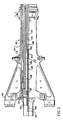
- a strut designated generally as 10 which strut includes an outer cylinder 12 adapted for connection to an aircraft by means of conventional braces 14.
- the strut 10 also includes an inner cylinder 16 having on one end thereof a convention bifurcated mounting 18.
- the mounting 18 is in the well known manner adapted for journaling of a wheel and axle (not shown).
- the strut is particularly of use in an aircraft having tricycle landing gear.
- the inner cylinder 16 is adapted for sliding movement within the outer cylinder 12 and has connected thereto by bolt 20 and nut 22 a metering pin 24.
- the metering pin 24 moves longitudinally with the inner cylinder 16.
- a piston 26 is positioned within the outer cylinder and has a piston head 28 on an end thereof opposite said inner cylinder 16 and metering pin 24.
- a quantity of incompressible fluid 30, such as oil, is provided within the inner cylinder.
- Compressed gas, designated at 32 which may be nitrogen, is contained between the fluid 30 and the piston head 28.
- This compressed gas serves to maintain the piston 26 in the retracted position as shown in Figure 1 and the inner cylinder 16 and associated landing gear wheel (not shown) in the fully extended position in the absence of any load on the assembly, as would be the case when the aircraft is in flight.
- the inner cylinder 16 in this fully extended position abuts against stop 34 of the outer cylinder 12, and the piston head 28 abuts against stop 37 of the outer cylinder.
- the metering pin 24 has a tapered surface orifice 25 so that upon longitudinal movement of the metering pin 24 toward the piston and outer cylinder fluid 30 may be metered from the inner cylinder to a longitudinal passage 35 from where it proceeds to the outer cylinder 12.
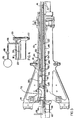
- means for applying fluid pressure to the piston head which means include a pneumatic gas storage vessel 36 piston which is connected through high pressure line 38 through extension/reversion valve 40 to the end of outer cylinder 12 adjacent the piston head 28.
- a pressure relief valve 42 and a charging valve 44 In association with the gas storage vessel 36 and high pressure lines 38 is a pressure relief valve 42 and a charging valve 44.
- the inner cylinder 16 will reciprocate within the outer cylinder and the combination of the oil 30 and compressing gas 32 will provide the conventional static load positioning action.
- the furthest that the inner cylinder 16 will extend is to the position shown in Figure 1 and the furthest that it will retract within the outer cylinder will be the position shown in Figure 2 wherein the end of the inner cylinder contacts the piston head 28 of piston 26.
- the inner cylinder will be between these two extreme positions. Due to the weight of the aircraft, the normal static position of the strut is approximately 80 % of the fully compressed length.
- valve 40 introduces compressed gas into contact through high pressure lines 38 to the piston head 28 of piston 26 to oppose the compressed gas within the outer cylinder 12. This action will cause the piston 26 to move toward the inner cylinder 16 and assert a hydraulic force against the inner cylinder 16 through the incompressible fluid 30 and compressible fluid 32.
- the incompressible fluid 30 will flow through orifice 25 and eventually the piston head 28 thereof may contact the end of the inner cylinder.
- the piston 26 and the inner cylinder 16 will then move together by contact at piston 26 which will then move to the fully extended position whown in Figure 3.
- valve 40 When the proper amount of momentum has been imparted to the aircraft valve 40 will be returned to its normal position to bleed off the compressed gas within the outer cylinder 12 and thus the action of the compressed gas 32 withinb the outer cylinder between the piston head 28 and the end of the inner cylinder 16 will cause the piston 26 to move longitudinally to the position shown in Figure 1 wherein the piston head 28 is against stop 37 of the outer cylinder. The strut is then in the normal operation mode required to provide the shock absorbing action for landing of the aircraft. __, _ _ _
- the storage vessel 36 and associated valves 40, 42 and 44 have been shown schematically and any suitable means may be used including means for operating the valves during takeoff of the aircraft wherein the use of the strut is required to facilitate shorter-distance takeoff.
- an internal valve 45 consisting of an internal valve sleeve 46 and valve piston 48.
- This sleeve and piston are mounted within the outer cylinder 12 for relative, reciprocal movement.
- the valve sleeve contains orifices 52.
- the valve piston contains orifices 54. These orifices are adapted for selective alignment.
- the valve piston 48 has a piston head 56 which is adapted to reciprocate between stops 58 and 60 of said sleeve and outer cylinder respectively.
- an activation valve 62 is connected by pressure line 64 to the aircraft hydraulic system (not shown) and to the outer cylinder 12 adjacent piston head 56.
- valve 62 When it is desired to adapt the strut for rough surface attenutation, the valve 62 is activated and aircraft hydraulic system fluid pressure is transmitted from the aircraft hydraulic system (not shown), through valve 62 and pressure line 64 to th valve piston head 56. This causes the associated piston 48 to slide relative to sleeve 46 until piston head 56 abuts against stop 58. This causes orifices 54 and 52 in piston 48 sleeve 46, respectively, to be in alignment. With these orifices in alignment, fluid 30 within the inner cylinder flows through these orifices froim the inner cylinder to the outer cylinder via the longitudinal passage 35. This is in addition to the fluid flow through the orifice 25 from the inner cylinder to the outer cylinder via the longitudinal passage 35. This prevents high pressure buildup of the fluid in the inner cylinder causing damaging forces to be transmitted to the aircraft structure when the wheel (not shown) on the end of the inner cylinder traverses rough surface conditions.
- FIG. 4 there is shown an alternate embodiment for providing for the flow of fluid from the inner cylinder incident to adapting the strut for rough surface attenuation.
- Pressure- line 66 is connected to the interior of the inner cylinder 16.
- Line 66 is also connected external to the strut to valve 68 and pressurized accumulator vessel 70.
- valve 68 would be opened to permit fluid from the inner cylinder to flow through line 66 to the pressurized accumulator vessel 70 when rough surface conditions cause the inner cylinder to slide toward the outer cylinder.
- fluid will flow from the pressurized accumulator vessel to the inner cylinder.
- Valve 68 can be operated by a signal from the pilot, from a pressure sensor sensing a predetermined pressure build-up within the inner cylinder 16, from an accelerometer mounted on the inner cylinder 16 which signals the valve 68 to open at a predetermined accelerated rate of reciprocal movement at the inner cylinder 16 within the outer cylinder 12, or from a load sensor mounted to the inner cylinder preset for a predetermined force applied to the inner cylinder.
- This structure obviates the need for internal valve 45 and associated structure.
- the strut static position may be selectively changed to provide additional rough surface attenuation by the addition of a quantity of compressed gas 72 charged between the outer cylinder 12 and the piston head 28 to provide additional stroking of the inner cylinder 16 within the outer cylinder 12. This prevents the inner cylinder 16 from striking the piston head 28 when the piston head 28 is in contact with the outer cylinder 12 thus preventing transmission of damaging forces into the aircraft structure.
Landscapes
- Engineering & Computer Science (AREA)
- Mechanical Engineering (AREA)
- Aviation & Aerospace Engineering (AREA)
- Fluid-Damping Devices (AREA)
- Vibration Dampers (AREA)
Claims (10)
Priority Applications (1)
| Application Number | Priority Date | Filing Date | Title |
|---|---|---|---|
| AT85306570T ATE36685T1 (de) | 1984-09-14 | 1985-09-16 | Stossdaempfungszylinder fuer ein flugzeugfahrwerk. |
Applications Claiming Priority (2)
| Application Number | Priority Date | Filing Date | Title |
|---|---|---|---|
| US06/650,608 US4637574A (en) | 1984-09-14 | 1984-09-14 | Attenuating, extendible shock-absorbing strut |
| US650608 | 1984-09-14 |
Publications (2)
| Publication Number | Publication Date |
|---|---|
| EP0174876A1 EP0174876A1 (de) | 1986-03-19 |
| EP0174876B1 true EP0174876B1 (de) | 1988-08-24 |
Family
ID=24609581
Family Applications (1)
| Application Number | Title | Priority Date | Filing Date |
|---|---|---|---|
| EP85306570A Expired EP0174876B1 (de) | 1984-09-14 | 1985-09-16 | Stossdämpfungszylinder für ein Flugzeugfahrwerk |
Country Status (5)
| Country | Link |
|---|---|
| US (1) | US4637574A (de) |
| EP (1) | EP0174876B1 (de) |
| AT (1) | ATE36685T1 (de) |
| CA (1) | CA1265498A (de) |
| DE (1) | DE3564553D1 (de) |
Families Citing this family (7)
| Publication number | Priority date | Publication date | Assignee | Title |
|---|---|---|---|---|
| US4746086A (en) * | 1987-03-09 | 1988-05-24 | Pneumo Abex Corporation | Nose landing gear jump strut assembly |
| FR2736613A1 (fr) * | 1989-07-13 | 1997-01-17 | Messier Hispano Sa | Train d'atterrissage sauteur |
| US6128951A (en) * | 1997-04-15 | 2000-10-10 | Trinity Airweighs, L.L.C. | Aircraft weight and center of gravity indicator |
| US7578465B2 (en) | 2004-01-20 | 2009-08-25 | Lord Corporation | Aircraft front nose landing gear and method of making an aircraft landing gear |
| US7571876B2 (en) * | 2004-01-20 | 2009-08-11 | Lord Corporation | Aircraft landing gear assembly shimmy damper |
| GB0714546D0 (en) * | 2007-07-26 | 2007-09-05 | Airbus Uk Ltd | Aircraft landing gear load sensor |
| WO2023091788A1 (en) | 2021-11-22 | 2023-05-25 | Nance C Kirk | Method and system for increasing the accuracy of aircraft weight and associated center of gravity determinations |
Family Cites Families (30)
| Publication number | Priority date | Publication date | Assignee | Title |
|---|---|---|---|---|
| US30896A (en) * | 1860-12-11 | Temple | ||
| US1317414A (en) * | 1919-09-30 | Babt atkihsoh | ||
| US2735634A (en) * | 1956-02-21 | fosness | ||
| US1068165A (en) * | 1910-02-24 | 1913-07-22 | Peter Peterson | Aerial navigation. |
| US1254898A (en) * | 1917-10-16 | 1918-01-29 | Norris H Frost | Self-launching aeroplane. |
| US1702682A (en) * | 1928-03-07 | 1929-02-19 | Charles D Carey | Automatic ground release for aeroplanes |
| US1767120A (en) * | 1928-11-26 | 1930-06-24 | Canfield Dudley | Take-off device for aeroplanes |
| US1745081A (en) * | 1929-02-26 | 1930-01-28 | Harry B Crumbaugh | Aeroplane |
| US2989983A (en) * | 1957-09-13 | 1961-06-27 | Bendix Westinghouse Automotive | Load control valve for vehicle air springs |
| US2977134A (en) * | 1957-09-18 | 1961-03-28 | Fried Krupp Mortoren Und Kraft | Device for controlling the air in air springs, especially for motor vehicles |
| US3011777A (en) * | 1957-11-06 | 1961-12-05 | Bendix Corp | Retractable strut |
| US3023740A (en) * | 1960-05-25 | 1962-03-06 | Fairchild Stratos Corp | Delayed pneumatic actuator |
| US3263986A (en) * | 1964-03-02 | 1966-08-02 | Bendix Corp | Shock absorber |
| US3292919A (en) * | 1964-12-21 | 1966-12-20 | Bendix Corp | Aircraft shock absorber |
| US3290038A (en) * | 1965-01-14 | 1966-12-06 | Bendix Corp | Extensible shock absorber |
| US3533613A (en) * | 1967-11-02 | 1970-10-13 | Lockheed Aircraft Corp | Axially retractable landing gear |
| US3874692A (en) * | 1969-12-09 | 1975-04-01 | Aisin Seiki | Air-suspension system for motor vehicles |
| GB1365869A (en) * | 1970-08-15 | 1974-09-04 | Dowty Rotol Ltd | Fluid spring shock absorber |
| GB1500754A (en) * | 1975-03-19 | 1978-02-08 | Automotive Prod Co Ltd | Aircraft undercarriages |
| US4075929A (en) * | 1976-01-28 | 1978-02-28 | The United States Of America As Represented By The Secretary Of The Air Force | Three stage thrusting device |
| JPS6018878B2 (ja) * | 1976-06-19 | 1985-05-13 | トキコ株式会社 | 緩衝器のガス封入方法 |
| YU39276B (en) * | 1976-07-12 | 1984-10-31 | Borut Horvat | Apparatus for actively damping vertical vibrations of a suspended mass, particularly parts of a vehicle, the driver and pasengers |
| DE2715895C2 (de) * | 1977-04-09 | 1979-05-31 | Messerschmitt-Boelkow-Blohm Gmbh, 8000 Muenchen | Federbein, vorzugsweise für Flugzeugfahrwerke |
| US4153266A (en) * | 1977-12-05 | 1979-05-08 | Uhls Jimmie J | Air shock apparatus for motorcycles |
| US4245854A (en) * | 1978-04-17 | 1981-01-20 | Curnutt Charles R | High pressure air suspension system |
| US4231554A (en) * | 1978-10-17 | 1980-11-04 | Ford Motor Company | Control valve for vehicle air springs and the like |
| US4300664A (en) * | 1978-11-27 | 1981-11-17 | Decoto Aircraft, Inc. | Locking device |
| US4273303A (en) * | 1979-03-16 | 1981-06-16 | The Boeing Company | Adaptive airplane landing gear |
| US4291850A (en) * | 1979-03-19 | 1981-09-29 | Lockheed Corporation | Contractable shock absorber strut |
| US4524929A (en) * | 1982-09-30 | 1985-06-25 | Grumman Aerospace Corporation | Short take off jump mode for airplane landing gear struts |
-
1984
- 1984-09-14 US US06/650,608 patent/US4637574A/en not_active Expired - Fee Related
-
1985
- 1985-09-13 CA CA000490728A patent/CA1265498A/en not_active Expired - Lifetime
- 1985-09-16 AT AT85306570T patent/ATE36685T1/de active
- 1985-09-16 EP EP85306570A patent/EP0174876B1/de not_active Expired
- 1985-09-16 DE DE8585306570T patent/DE3564553D1/de not_active Expired
Also Published As
| Publication number | Publication date |
|---|---|
| EP0174876A1 (de) | 1986-03-19 |
| CA1265498A (en) | 1990-02-06 |
| DE3564553D1 (en) | 1988-09-29 |
| ATE36685T1 (de) | 1988-09-15 |
| US4637574A (en) | 1987-01-20 |
Similar Documents
| Publication | Publication Date | Title |
|---|---|---|
| US4381857A (en) | Programmed oleo-pneumatic shock absorber | |
| US4445672A (en) | Shock absorber-actuator | |
| US3696894A (en) | Acceleration sensitive shock absorber valve | |
| US7926633B2 (en) | Compact shock absorber for an aircraft undercarriage, and an undercarriage including such a shock absorber | |
| US3533613A (en) | Axially retractable landing gear | |
| US4537374A (en) | Structural supports and aircraft landing gears including such supports | |
| US5908174A (en) | Automatic shrink shock strut for an aircraft landing gear | |
| US4284255A (en) | Shock absorbers and shock absorber struts, notably for aerodyne landing gear | |
| US2735634A (en) | fosness | |
| CN104895995B (zh) | 小型无人机起落架缓冲器 | |
| CA2348270A1 (en) | Landing gear shock absorber with variable viscosity fluid | |
| US5996979A (en) | Aircraft shock strut having an improved piston head | |
| US2814482A (en) | Aircraft landing gear shock strut | |
| US2868482A (en) | Retractable landing gear | |
| EP0174876B1 (de) | Stossdämpfungszylinder für ein Flugzeugfahrwerk | |
| US2559451A (en) | Landing gear with drag strut dynamic damper | |
| EP3345828B1 (de) | Zweistufiges federbein, das eine geringe anfängliche druckbelastung erlaubt | |
| US7967119B2 (en) | Telescopic member having an overridable internal abutment | |
| US3062485A (en) | Aircraft landing gear for use on catapult aircraft | |
| US3292919A (en) | Aircraft shock absorber | |
| EP0282222A2 (de) | Federbeinzylinder eines Bugfahrwerks für Sprungstart | |
| US3290037A (en) | Multiple orifice oleo-pneumatic shock/strut | |
| US3653682A (en) | Energy absorbing device | |
| EP3508420B1 (de) | Hydraulische systeme zum schrumpfen von fahrwerk | |
| US2916283A (en) | Landing gear construction |
Legal Events
| Date | Code | Title | Description |
|---|---|---|---|
| PUAI | Public reference made under article 153(3) epc to a published international application that has entered the european phase |
Free format text: ORIGINAL CODE: 0009012 |
|
| AK | Designated contracting states |
Kind code of ref document: A1 Designated state(s): AT BE CH DE FR GB IT LI LU NL SE |
|
| 17P | Request for examination filed |
Effective date: 19860515 |
|
| 17Q | First examination report despatched |
Effective date: 19870113 |
|
| GRAA | (expected) grant |
Free format text: ORIGINAL CODE: 0009210 |
|
| AK | Designated contracting states |
Kind code of ref document: B1 Designated state(s): AT BE CH DE FR GB IT LI LU NL SE |
|
| REF | Corresponds to: |
Ref document number: 36685 Country of ref document: AT Date of ref document: 19880915 Kind code of ref document: T |
|
| REF | Corresponds to: |
Ref document number: 3564553 Country of ref document: DE Date of ref document: 19880929 |
|
| ET | Fr: translation filed | ||
| ITF | It: translation for a ep patent filed | ||
| PLBE | No opposition filed within time limit |
Free format text: ORIGINAL CODE: 0009261 |
|
| STAA | Information on the status of an ep patent application or granted ep patent |
Free format text: STATUS: NO OPPOSITION FILED WITHIN TIME LIMIT |
|
| 26N | No opposition filed | ||
| GBPC | Gb: european patent ceased through non-payment of renewal fee | ||
| REG | Reference to a national code |
Ref country code: GB Ref legal event code: 728C |
|
| REG | Reference to a national code |
Ref country code: GB Ref legal event code: 728A |
|
| PGFP | Annual fee paid to national office [announced via postgrant information from national office to epo] |
Ref country code: LU Payment date: 19930723 Year of fee payment: 9 |
|
| PGFP | Annual fee paid to national office [announced via postgrant information from national office to epo] |
Ref country code: GB Payment date: 19930806 Year of fee payment: 9 |
|
| PGFP | Annual fee paid to national office [announced via postgrant information from national office to epo] |
Ref country code: AT Payment date: 19930820 Year of fee payment: 9 |
|
| PGFP | Annual fee paid to national office [announced via postgrant information from national office to epo] |
Ref country code: SE Payment date: 19930824 Year of fee payment: 9 |
|
| PGFP | Annual fee paid to national office [announced via postgrant information from national office to epo] |
Ref country code: FR Payment date: 19930910 Year of fee payment: 9 |
|
| PGFP | Annual fee paid to national office [announced via postgrant information from national office to epo] |
Ref country code: DE Payment date: 19930928 Year of fee payment: 9 Ref country code: CH Payment date: 19930928 Year of fee payment: 9 |
|
| ITTA | It: last paid annual fee | ||
| PGFP | Annual fee paid to national office [announced via postgrant information from national office to epo] |
Ref country code: NL Payment date: 19930930 Year of fee payment: 9 |
|
| PGFP | Annual fee paid to national office [announced via postgrant information from national office to epo] |
Ref country code: BE Payment date: 19931007 Year of fee payment: 9 |
|
| EPTA | Lu: last paid annual fee | ||
| PG25 | Lapsed in a contracting state [announced via postgrant information from national office to epo] |
Ref country code: LU Free format text: LAPSE BECAUSE OF NON-PAYMENT OF DUE FEES Effective date: 19940916 Ref country code: GB Effective date: 19940916 Ref country code: AT Effective date: 19940916 |
|
| PG25 | Lapsed in a contracting state [announced via postgrant information from national office to epo] |
Ref country code: SE Effective date: 19940917 |
|
| PG25 | Lapsed in a contracting state [announced via postgrant information from national office to epo] |
Ref country code: LI Effective date: 19940930 Ref country code: CH Effective date: 19940930 Ref country code: BE Effective date: 19940930 |
|
| EAL | Se: european patent in force in sweden |
Ref document number: 85306570.4 |
|
| BERE | Be: lapsed |
Owner name: MENASCO INC. Effective date: 19940930 |
|
| PG25 | Lapsed in a contracting state [announced via postgrant information from national office to epo] |
Ref country code: NL Effective date: 19950401 |
|
| GBPC | Gb: european patent ceased through non-payment of renewal fee |
Effective date: 19940916 |
|
| NLV4 | Nl: lapsed or anulled due to non-payment of the annual fee | ||
| PG25 | Lapsed in a contracting state [announced via postgrant information from national office to epo] |
Ref country code: FR Effective date: 19950531 |
|
| REG | Reference to a national code |
Ref country code: CH Ref legal event code: PL |
|
| PG25 | Lapsed in a contracting state [announced via postgrant information from national office to epo] |
Ref country code: DE Effective date: 19950601 |
|
| EUG | Se: european patent has lapsed |
Ref document number: 85306570.4 |
|
| REG | Reference to a national code |
Ref country code: FR Ref legal event code: ST |