EP0174903A2 - Dispositif de fixation sur un arbre pour un ensemble de palier - Google Patents
Dispositif de fixation sur un arbre pour un ensemble de palier Download PDFInfo
- Publication number
- EP0174903A2 EP0174903A2 EP85630155A EP85630155A EP0174903A2 EP 0174903 A2 EP0174903 A2 EP 0174903A2 EP 85630155 A EP85630155 A EP 85630155A EP 85630155 A EP85630155 A EP 85630155A EP 0174903 A2 EP0174903 A2 EP 0174903A2
- Authority
- EP
- European Patent Office
- Prior art keywords
- annular
- inner ring
- finger extensions
- ring finger
- breadth
- Prior art date
- Legal status (The legal status is an assumption and is not a legal conclusion. Google has not performed a legal analysis and makes no representation as to the accuracy of the status listed.)
- Granted
Links
- 230000000712 assembly Effects 0.000 title abstract description 3
- 238000000429 assembly Methods 0.000 title abstract description 3
- 238000005452 bending Methods 0.000 claims abstract description 8
- 238000010008 shearing Methods 0.000 claims abstract description 5
- 238000005096 rolling process Methods 0.000 claims description 11
- 230000004308 accommodation Effects 0.000 claims description 4
- 230000005540 biological transmission Effects 0.000 claims description 3
- 239000002184 metal Substances 0.000 description 3
- 230000001050 lubricating effect Effects 0.000 description 2
- 238000004519 manufacturing process Methods 0.000 description 2
- 230000006835 compression Effects 0.000 description 1
- 238000007906 compression Methods 0.000 description 1
- 238000010276 construction Methods 0.000 description 1
- 239000004519 grease Substances 0.000 description 1
- 238000000034 method Methods 0.000 description 1
Images

Classifications
-
- F—MECHANICAL ENGINEERING; LIGHTING; HEATING; WEAPONS; BLASTING
- F16—ENGINEERING ELEMENTS AND UNITS; GENERAL MEASURES FOR PRODUCING AND MAINTAINING EFFECTIVE FUNCTIONING OF MACHINES OR INSTALLATIONS; THERMAL INSULATION IN GENERAL
- F16C—SHAFTS; FLEXIBLE SHAFTS; ELEMENTS OR CRANKSHAFT MECHANISMS; ROTARY BODIES OTHER THAN GEARING ELEMENTS; BEARINGS
- F16C35/00—Rigid support of bearing units; Housings, e.g. caps, covers
- F16C35/04—Rigid support of bearing units; Housings, e.g. caps, covers in the case of ball or roller bearings
- F16C35/06—Mounting or dismounting of ball or roller bearings; Fixing them onto shaft or in housing
- F16C35/063—Fixing them on the shaft
-
- F—MECHANICAL ENGINEERING; LIGHTING; HEATING; WEAPONS; BLASTING
- F16—ENGINEERING ELEMENTS AND UNITS; GENERAL MEASURES FOR PRODUCING AND MAINTAINING EFFECTIVE FUNCTIONING OF MACHINES OR INSTALLATIONS; THERMAL INSULATION IN GENERAL
- F16C—SHAFTS; FLEXIBLE SHAFTS; ELEMENTS OR CRANKSHAFT MECHANISMS; ROTARY BODIES OTHER THAN GEARING ELEMENTS; BEARINGS
- F16C23/00—Bearings for exclusively rotary movement adjustable for aligning or positioning
- F16C23/06—Ball or roller bearings
- F16C23/08—Ball or roller bearings self-adjusting
- F16C23/082—Ball or roller bearings self-adjusting by means of at least one substantially spherical surface
- F16C23/084—Ball or roller bearings self-adjusting by means of at least one substantially spherical surface sliding on a complementary spherical surface
-
- F—MECHANICAL ENGINEERING; LIGHTING; HEATING; WEAPONS; BLASTING
- F16—ENGINEERING ELEMENTS AND UNITS; GENERAL MEASURES FOR PRODUCING AND MAINTAINING EFFECTIVE FUNCTIONING OF MACHINES OR INSTALLATIONS; THERMAL INSULATION IN GENERAL
- F16D—COUPLINGS FOR TRANSMITTING ROTATION; CLUTCHES; BRAKES
- F16D1/00—Couplings for rigidly connecting two coaxial shafts or other movable machine elements
- F16D1/06—Couplings for rigidly connecting two coaxial shafts or other movable machine elements for attachment of a member on a shaft or on a shaft-end
- F16D1/08—Couplings for rigidly connecting two coaxial shafts or other movable machine elements for attachment of a member on a shaft or on a shaft-end with clamping hub; with hub and longitudinal key
- F16D1/0852—Couplings for rigidly connecting two coaxial shafts or other movable machine elements for attachment of a member on a shaft or on a shaft-end with clamping hub; with hub and longitudinal key with radial clamping between the mating surfaces of the hub and shaft
- F16D1/0864—Couplings for rigidly connecting two coaxial shafts or other movable machine elements for attachment of a member on a shaft or on a shaft-end with clamping hub; with hub and longitudinal key with radial clamping between the mating surfaces of the hub and shaft due to tangential loading of the hub, e.g. a split hub
-
- F—MECHANICAL ENGINEERING; LIGHTING; HEATING; WEAPONS; BLASTING
- F16—ENGINEERING ELEMENTS AND UNITS; GENERAL MEASURES FOR PRODUCING AND MAINTAINING EFFECTIVE FUNCTIONING OF MACHINES OR INSTALLATIONS; THERMAL INSULATION IN GENERAL
- F16C—SHAFTS; FLEXIBLE SHAFTS; ELEMENTS OR CRANKSHAFT MECHANISMS; ROTARY BODIES OTHER THAN GEARING ELEMENTS; BEARINGS
- F16C19/00—Bearings with rolling contact, for exclusively rotary movement
- F16C19/02—Bearings with rolling contact, for exclusively rotary movement with bearing balls essentially of the same size in one or more circular rows
- F16C19/04—Bearings with rolling contact, for exclusively rotary movement with bearing balls essentially of the same size in one or more circular rows for radial load mainly
- F16C19/06—Bearings with rolling contact, for exclusively rotary movement with bearing balls essentially of the same size in one or more circular rows for radial load mainly with a single row or balls
Definitions
- the present invention relates to bearing assembly arrangements and, more particularly, to a shaft locking arrangement for bearing assemblies.
- novel features of the present invention can be utilized in combination with any one of a number of known force applying arrangements for securing a bearing assembly to a shaft and are particularly adaptable to the compressible collar and inner ring finger extensions of the known SKWEZLOC arrangement resulting in the concomitant advantages of near-perfect shaft-ring concentricity and an increased capacity for locking under high loads and for high shaft operating speeds.
- the present invention provides a new and useful shaft locking arrangement which is straightforward and economical in manufacture, operation and assembly, requiring a minimum of tooling and parts but requiring no additional assembly steps.
- the arrangement of the present invention serves to increase shaft locking capacity with improved accommodation for radial and thrust or axial loads, or either of them, accomplishing a locking capability of two tightening screws with only one screw by placing inner ring extensions during shaft locking in less shear and more bending through a unique and novel arrangement wherein radial forces are exerted on the outermost portions bf inner ring extensions with the inner most portions being relieved to convert what would otherwise be shear stresses to bending stresses.
- the present invention provides a bearing assembly comprising: inner and outer annular bearing rings, each including bearing raceways positioned in opposed annular spaced relation to each other; a rolling element loaded annular cage mounted in the space between the opposed raceways with the rolling elements therein engaging in the opposed raceways; the inner bearing ring including slotted inner ring finger extensions extending in cantilever fashion from at least one end thereof; and force means to compress the inner ring finger extensions when such inner ring finger extensions are mounted on a shaft to lock the inner ring tightly to the shaft; the inner ring finger extensions having a recessed annular grooved area extending at least partially theraround in spaced relation from the outer ends of the finger extensions and being of sufficient breadth and depth to convert what would otherwise be shearing stresses along such area to bending stresses and thus improve radial and thrust accommodation capacity and rotational torque transmission.
- shaft 2 is disclosed in Figure 1 as passing through bearing assembly 3.
- Assembly 3 includes annular inner ring 4 having a grooved raceway 6 which is wear hardened to extend the bearing life.
- annular outer ring 7 Surrounding annular inner ring 4 in spaced relation therefrom, is annular outer ring 7 having grooved raceway 8 disposed therein in opposed relationship to inner ring raceway 6, the raceways serving to receive in nesting reationship therewith a plurality of spaced ball or rolling elements 9 mounted in rolling element pockets of rolling element cage 11.
- a lubricating passage 12 is provided in outer bearing ring 7 which is aligned with a passage 13 in bearing assembly housing or pillow block 14 in which bearing assembly 3 is mounted.
- a suitable threaded castellated adaptor or grease fitting 16 serves to seal aligned lubricating passages 12 and 13.
- annular inner flingers 17 and outer flingers 18 with annular seals therebetween are pressfitted respectively on outer and inner bearing rings 4 and 7 on either side of loaded rolling element cage 11.
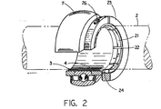
- inner bearing ring 4 includes finger extensions 21 extending therefromin annular cantilever fashion to surround shaft 2. These extensions are provided with a plurality of slots 22 parallel the axis of shaft rotation to permit radial compression by a surrounding slotted locking collar 23, a portion of which in Figure 2 is broken away in order to disclose more fully the inner ring 4 and finger extensions 21 of the inner ring.
- the present invention contemplates the use of other locking force arrangements besides slotted collar 23 as well as use of a different number of finger ring extensions from that as disclosed.
- the breadth of collar 23 is substantially equal to the breadth of the inner ring finger extensions 21 which facilitates collar mounting during assembly to assure aligned seating or “squaring” of the collar but it is to be understood, for reasons explained hereinafter, that the collar breadth could be more or less.
- inner ring finger extensions 21 are provided with an annular groove or recess 24 which extends annularly around the outer surface of the inner ring finger extensions in spaced relation from the cantilevered extremities of the extension.
- the breadth of groove 24 is approximately one half the breadth of locking collar 23 with the breadth of the groove extending to the main body.of.inner ring 4.
- slot or recess 24 be of a minor depth to obtain the desired results of the present invention and, advantageously, a depth of o,5 mm will suffice. Further, it is important that the slot not be so deep as to jeopardize the strength of the metal and the capability of the grooved or recessed area to accommodate bending torque.
- screw 26 threaded in annular collar 23 to extend tangentially therethrough normal to the slot in collar 23 is screw 26, the screw being recessed to receive an hexagonal wrench for lineal adjustment thereof to obtain the desired tightening or loosening of collar 23 about inner ring finger extensions 21.
- the longitudinal axis of screw 26 is positioned immediately above and in alignment with that outer edge or shore of grove 24 closest to the cantilevered extremities of inner ring extensions 21 so as to maximize the force translated to that portion of the external surface of the inner ring finger extensions against which collar 23 abuts when screw 26 is tightened.
Landscapes
- Engineering & Computer Science (AREA)
- General Engineering & Computer Science (AREA)
- Mechanical Engineering (AREA)
- Rolling Contact Bearings (AREA)
- Mounting Of Bearings Or Others (AREA)
Applications Claiming Priority (2)
| Application Number | Priority Date | Filing Date | Title |
|---|---|---|---|
| US650452 | 1984-09-14 | ||
| US06/650,452 US4537519A (en) | 1984-09-14 | 1984-09-14 | Shaft locking device for bearing assemblies |
Publications (3)
| Publication Number | Publication Date |
|---|---|
| EP0174903A2 true EP0174903A2 (fr) | 1986-03-19 |
| EP0174903A3 EP0174903A3 (en) | 1987-07-22 |
| EP0174903B1 EP0174903B1 (fr) | 1990-01-17 |
Family
ID=24608970
Family Applications (1)
| Application Number | Title | Priority Date | Filing Date |
|---|---|---|---|
| EP85630155A Expired - Lifetime EP0174903B1 (fr) | 1984-09-14 | 1985-09-12 | Dispositif de fixation sur un arbre pour un ensemble de palier |
Country Status (7)
| Country | Link |
|---|---|
| US (1) | US4537519A (fr) |
| EP (1) | EP0174903B1 (fr) |
| JP (1) | JPS6174913A (fr) |
| KR (1) | KR930010412B1 (fr) |
| CA (1) | CA1216437A (fr) |
| DE (1) | DE3575455D1 (fr) |
| MX (1) | MX162715A (fr) |
Cited By (2)
| Publication number | Priority date | Publication date | Assignee | Title |
|---|---|---|---|---|
| DE4311504C1 (de) * | 1993-04-07 | 1994-06-01 | Max Lamb Kg | Präzisionsanstellmutter |
| IT202000007048A1 (it) * | 2020-04-03 | 2021-10-03 | Skf Ab | Unita’ cuscinetto con collare di serraggio concentrico |
Families Citing this family (27)
| Publication number | Priority date | Publication date | Assignee | Title |
|---|---|---|---|---|
| US4673302A (en) * | 1986-06-30 | 1987-06-16 | Emerson Electric Co. | Double row cylindrical expansion bearing |
| US4728202A (en) * | 1987-01-14 | 1988-03-01 | Emerson Electric Co. | Shaft locking collar for bearing assemblies |
| US5002406A (en) * | 1990-02-20 | 1991-03-26 | Emerson Electric Co. | Sealing structure for a spherical bearing assembly |
| US5417500A (en) * | 1993-09-13 | 1995-05-23 | Reliance Electric Industrial Company | Bearing assembly utilizing improved clamping collar |
| US5630671A (en) * | 1995-08-31 | 1997-05-20 | The Torrington Company | Locking device for a bearing assembly |
| US6336748B2 (en) | 1999-01-22 | 2002-01-08 | Emerson Power Transmission Manufacturing, L.P. | Shaft locking device for bearing assemblies |
| USRE39027E1 (en) | 1997-02-07 | 2006-03-21 | Emerson Power Transmission Manufacturing, L.P. | Shaft locking device for bearing assemblies |
| WO2000003150A1 (fr) | 1998-07-08 | 2000-01-20 | Asahi Seiko Co., Ltd. | Coussinet muni d'un mecanisme de fixation se fixant au coussinet |
| US6036372A (en) * | 1998-07-31 | 2000-03-14 | Ami Bearings, Inc. | Bearing assembly with locking collar |
| US6840679B2 (en) | 2002-03-05 | 2005-01-11 | Peer Bearing Company | Bearing assembly and locking collar |
| US6817769B2 (en) * | 2002-09-30 | 2004-11-16 | Emerson Power Transmission Manufacturing, L.P. | Roller bearing having high performance bearing seal and cartridge |
| DE10310639A1 (de) * | 2003-03-10 | 2004-09-23 | Volker Limbeck | Abtriebskonfiguration für Windenergieanlagen |
| US7300210B2 (en) * | 2004-01-08 | 2007-11-27 | Emerson Power Transmission Manufacturing, Llp | Bearing locking collar with laminated plates |
| US20050185869A1 (en) * | 2004-02-20 | 2005-08-25 | Lenick Louis J. | High torque locking collar for a bearing assembly |
| KR100687009B1 (ko) * | 2005-06-23 | 2007-02-26 | 세메스 주식회사 | 기판 반송을 위한 샤프트 장치 |
| US7306375B2 (en) * | 2005-11-02 | 2007-12-11 | Peer Bearing Company | Bearing locking collar retainer |
| ATE551539T1 (de) * | 2006-01-03 | 2012-04-15 | Gkn Driveline North America | Homokinetische kupplung mit direktem drehmomentfluss und klemmhülsenverbindung |
| US7637665B2 (en) * | 2006-06-30 | 2009-12-29 | Emerson Power Transmission Corporation | Bearing assembly and resilient seal element |
| US8333515B2 (en) * | 2006-06-30 | 2012-12-18 | Emerson Power Transmission Corporation | External bearing shroud |
| US20100272383A1 (en) * | 2009-04-28 | 2010-10-28 | Edt Corp. | Split locking sleeve |
| JP2013079679A (ja) * | 2011-10-04 | 2013-05-02 | Masaroku Takatori | リング類を軸に固定するための固定リング |
| IN2013MU03206A (fr) * | 2013-10-10 | 2015-07-03 | Emerson Power Transmission Corp | |
| US9388851B1 (en) * | 2014-12-22 | 2016-07-12 | Schaeffler Technologies AG & Co. KG | Split cylindrical roller bearing |
| IT202000005509A1 (it) * | 2020-03-16 | 2021-09-16 | Skf Ab | Unita’ cuscinetto con sistema di serraggio ottimizzato |
| IT202100022952A1 (it) * | 2021-09-07 | 2023-03-07 | Skf Ab | Unita’ cuscinetto con disco di protezione |
| US11536318B1 (en) * | 2021-09-20 | 2022-12-27 | Aktiebolaget Skf | Bearing inner ring with integral mounting means |
| JP2024155508A (ja) | 2023-04-21 | 2024-10-31 | Ntn株式会社 | 軸受 |
Family Cites Families (9)
| Publication number | Priority date | Publication date | Assignee | Title |
|---|---|---|---|---|
| US17838A (en) * | 1857-07-21 | Pianofortes | ||
| US26591A (en) * | 1859-12-27 | Jesse jacobs | ||
| USRE17838E (en) | 1930-10-21 | gayman | ||
| GB696303A (en) * | 1951-02-05 | 1953-08-26 | Julius Edward Shafer | Improvements in or relating to bearing assembly |
| GB1027499A (en) * | 1963-12-04 | 1966-04-27 | Cooper Roller Bearings Company | Improvements in or relating to roller bearings |
| GB1055917A (en) * | 1965-10-27 | 1967-01-18 | Rolls Royce | Bearing assembly and method of manufacturing the same |
| US3276828A (en) * | 1965-11-17 | 1966-10-04 | Adamson Stephens Mfg Co | Antifriction bearings including means for coupling them to shafts |
| USRE26591E (en) | 1967-02-10 | 1969-05-27 | Split roller bearings | |
| US3588208A (en) * | 1969-09-19 | 1971-06-28 | Tek Bearing Co | Locking device for antifriction bearing ring |
-
1984
- 1984-09-14 US US06/650,452 patent/US4537519A/en not_active Expired - Lifetime
-
1985
- 1985-08-28 CA CA000489564A patent/CA1216437A/fr not_active Expired
- 1985-09-05 JP JP60196860A patent/JPS6174913A/ja active Granted
- 1985-09-10 KR KR1019850006592A patent/KR930010412B1/ko not_active Expired - Fee Related
- 1985-09-12 DE DE8585630155T patent/DE3575455D1/de not_active Expired - Lifetime
- 1985-09-12 EP EP85630155A patent/EP0174903B1/fr not_active Expired - Lifetime
- 1985-09-13 MX MX206617A patent/MX162715A/es unknown
Cited By (3)
| Publication number | Priority date | Publication date | Assignee | Title |
|---|---|---|---|---|
| DE4311504C1 (de) * | 1993-04-07 | 1994-06-01 | Max Lamb Kg | Präzisionsanstellmutter |
| IT202000007048A1 (it) * | 2020-04-03 | 2021-10-03 | Skf Ab | Unita’ cuscinetto con collare di serraggio concentrico |
| US12092159B2 (en) | 2020-04-03 | 2024-09-17 | Aktiebolaget Skf | Bearing unit with concentric clamping collar |
Also Published As
| Publication number | Publication date |
|---|---|
| JPS6174913A (ja) | 1986-04-17 |
| KR860002662A (ko) | 1986-04-28 |
| US4537519A (en) | 1985-08-27 |
| EP0174903A3 (en) | 1987-07-22 |
| DE3575455D1 (de) | 1990-02-22 |
| KR930010412B1 (ko) | 1993-10-23 |
| EP0174903B1 (fr) | 1990-01-17 |
| CA1216437A (fr) | 1987-01-13 |
| JPH0467046B2 (fr) | 1992-10-27 |
| MX162715A (es) | 1991-06-17 |
Similar Documents
| Publication | Publication Date | Title |
|---|---|---|
| US4537519A (en) | Shaft locking device for bearing assemblies | |
| US5058262A (en) | Attachment of a hard bearing ring to the bore surface of a housing or to the lateral surface of a journal | |
| US4728202A (en) | Shaft locking collar for bearing assemblies | |
| US7344313B2 (en) | Taper lock bearing assembly | |
| US7186030B2 (en) | Expandable shaft assembly | |
| US6036372A (en) | Bearing assembly with locking collar | |
| EP0287296A2 (fr) | Construction de palier céramique | |
| CN1243923A (zh) | 轴承组件 | |
| US5330284A (en) | Apparatus for mounting and dismounting bearings | |
| US7588371B2 (en) | Bearing assembly | |
| US4480879A (en) | Rolling bearing arrangement for lengthwise movement of a housing on one or two mutually parallel rails | |
| EP0156104A1 (fr) | Dispositif pour la fixation d'un organe de machine | |
| US20030169954A1 (en) | Bearing assembly and locking collar | |
| US20020106260A1 (en) | Screw connection with countersunk screw | |
| CA1245699A (fr) | Dispositif de montage d'un roulement sur un arbre | |
| EP0251016A1 (fr) | Dispositif de montage avec douille de serrage | |
| US4026614A (en) | Rolling contact bearing assembly | |
| KR20030061281A (ko) | 클램프너트 및 콜릿척 | |
| US5136777A (en) | Attachment of a hard bearing ring to the bore surface of a housing or to the lateral surface of a journal | |
| EP0348365B1 (fr) | Dispositif de fixation d'un palier à roulement sur arbre | |
| US4139317A (en) | Bearing locking assembly | |
| CN212803980U (zh) | 一种十字滑块联轴器 | |
| JPH03500329A (ja) | カムフォロワ組立体 | |
| EP1111258A1 (fr) | Coussinet muni d'un mecanisme de fixation se fixant au coussinet | |
| KR920006494B1 (ko) | 패스너에 응력을 부여하기 위한 장치 |
Legal Events
| Date | Code | Title | Description |
|---|---|---|---|
| PUAI | Public reference made under article 153(3) epc to a published international application that has entered the european phase |
Free format text: ORIGINAL CODE: 0009012 |
|
| AK | Designated contracting states |
Kind code of ref document: A2 Designated state(s): DE FR GB IT |
|
| PUAL | Search report despatched |
Free format text: ORIGINAL CODE: 0009013 |
|
| AK | Designated contracting states |
Kind code of ref document: A3 Designated state(s): DE FR GB IT |
|
| 17P | Request for examination filed |
Effective date: 19870918 |
|
| 17Q | First examination report despatched |
Effective date: 19880706 |
|
| GRAA | (expected) grant |
Free format text: ORIGINAL CODE: 0009210 |
|
| AK | Designated contracting states |
Kind code of ref document: B1 Designated state(s): DE FR GB IT |
|
| ET | Fr: translation filed | ||
| REF | Corresponds to: |
Ref document number: 3575455 Country of ref document: DE Date of ref document: 19900222 |
|
| ITF | It: translation for a ep patent filed | ||
| PLBE | No opposition filed within time limit |
Free format text: ORIGINAL CODE: 0009261 |
|
| STAA | Information on the status of an ep patent application or granted ep patent |
Free format text: STATUS: NO OPPOSITION FILED WITHIN TIME LIMIT |
|
| 26N | No opposition filed | ||
| ITTA | It: last paid annual fee | ||
| REG | Reference to a national code |
Ref country code: GB Ref legal event code: IF02 |
|
| PGFP | Annual fee paid to national office [announced via postgrant information from national office to epo] |
Ref country code: GB Payment date: 20040908 Year of fee payment: 20 |
|
| PGFP | Annual fee paid to national office [announced via postgrant information from national office to epo] |
Ref country code: FR Payment date: 20040920 Year of fee payment: 20 |
|
| PGFP | Annual fee paid to national office [announced via postgrant information from national office to epo] |
Ref country code: DE Payment date: 20041102 Year of fee payment: 20 |
|
| PG25 | Lapsed in a contracting state [announced via postgrant information from national office to epo] |
Ref country code: GB Free format text: LAPSE BECAUSE OF EXPIRATION OF PROTECTION Effective date: 20050911 |
|
| REG | Reference to a national code |
Ref country code: GB Ref legal event code: PE20 |