EP0175012A1 - Verrou rotatif avec moyen d'arrêt, actionné par une clé - Google Patents
Verrou rotatif avec moyen d'arrêt, actionné par une clé Download PDFInfo
- Publication number
- EP0175012A1 EP0175012A1 EP84111169A EP84111169A EP0175012A1 EP 0175012 A1 EP0175012 A1 EP 0175012A1 EP 84111169 A EP84111169 A EP 84111169A EP 84111169 A EP84111169 A EP 84111169A EP 0175012 A1 EP0175012 A1 EP 0175012A1
- Authority
- EP
- European Patent Office
- Prior art keywords
- key
- mask
- cam lock
- lock according
- locking element
- Prior art date
- Legal status (The legal status is an assumption and is not a legal conclusion. Google has not performed a legal analysis and makes no representation as to the accuracy of the status listed.)
- Granted
Links
Images

Classifications
-
- H—ELECTRICITY
- H02—GENERATION; CONVERSION OR DISTRIBUTION OF ELECTRIC POWER
- H02B—BOARDS, SUBSTATIONS OR SWITCHING ARRANGEMENTS FOR THE SUPPLY OR DISTRIBUTION OF ELECTRIC POWER
- H02B1/00—Frameworks, boards, panels, desks, casings; Details of substations or switching arrangements
- H02B1/14—Shutters or guards for preventing access to contacts
-
- E—FIXED CONSTRUCTIONS
- E05—LOCKS; KEYS; WINDOW OR DOOR FITTINGS; SAFES
- E05B—LOCKS; ACCESSORIES THEREFOR; HANDCUFFS
- E05B15/00—Other details of locks; Parts for engagement by bolts of fastening devices
- E05B15/16—Use of special materials for parts of locks
-
- E—FIXED CONSTRUCTIONS
- E05—LOCKS; KEYS; WINDOW OR DOOR FITTINGS; SAFES
- E05B—LOCKS; ACCESSORIES THEREFOR; HANDCUFFS
- E05B15/00—Other details of locks; Parts for engagement by bolts of fastening devices
- E05B15/16—Use of special materials for parts of locks
- E05B15/1635—Use of special materials for parts of locks of plastics materials
-
- E—FIXED CONSTRUCTIONS
- E05—LOCKS; KEYS; WINDOW OR DOOR FITTINGS; SAFES
- E05B—LOCKS; ACCESSORIES THEREFOR; HANDCUFFS
- E05B35/00—Locks for use with special keys or a plurality of keys ; keys therefor
-
- E—FIXED CONSTRUCTIONS
- E05—LOCKS; KEYS; WINDOW OR DOOR FITTINGS; SAFES
- E05C—BOLTS OR FASTENING DEVICES FOR WINGS, SPECIALLY FOR DOORS OR WINDOWS
- E05C3/00—Fastening devices with bolts moving pivotally or rotatively
- E05C3/02—Fastening devices with bolts moving pivotally or rotatively without latching action
- E05C3/04—Fastening devices with bolts moving pivotally or rotatively without latching action with operating handle or equivalent member rigid with the bolt
- E05C3/041—Fastening devices with bolts moving pivotally or rotatively without latching action with operating handle or equivalent member rigid with the bolt rotating about an axis perpendicular to the surface on which the fastener is mounted
- E05C3/042—Fastening devices with bolts moving pivotally or rotatively without latching action with operating handle or equivalent member rigid with the bolt rotating about an axis perpendicular to the surface on which the fastener is mounted the handle being at one side, the bolt at the other side or inside the wing
Definitions
- the invention relates to a lockable cam lock which can be actuated by a socket wrench, with a lock core which can be actuated against compression spring loading in a lock housing and which is rotatably and lockably mounted, the lock core consisting of a front section for receiving the socket key, a fuselage or center section and a prismatic foot or rear section.
- one or more cam locks per door leaf are often used to lock the cabinet doors, which are actuated by means of double-bit keys or multi-square mandrel keys, in particular square mandrel keys.
- the control cabinet doors and their locks are subject to strong vibrations and vibrations, which lead to unwanted and often dangerous opening of the cabinet door, especially the control cabinet door, when the locks are not secured.
- a key catch for the lock which serves to prevent or at least make it more difficult for unauthorized persons to open such doors with the aid of keys and tools which are not intended for opening the door.
- the key catch has an opening adapted to the cross section of the key and thereby makes it difficult to insert keys or tools with a different profile shape or even makes this impossible.
- double-bit keys of certain dimensions are provided in accordance with the German standard, which have two opposing key bits and an axial bore each of standardized dimensions.
- These double-bit keys include a keyhole which is also standardized in terms of its dimensions and which is formed, for example, by the key catch.
- Such unwanted shifts can also occur due to vibrations, the z. B. arise from the devices arranged inside the cabinets, but also by transporting the cabinets, for. B. when transporting control cabinets from the factory to the installation site on trucks. At the The place of installation has then often shifted the locks a bit and the locks can no longer or not easily be opened with the key provided for them, which is very annoying for the user.
- Lockable sash lock operated cam locks have therefore been developed which prevent such undesired displacements in the event of vibrations.
- US-A-36 61 001 shows a locking device which can be actuated by a wrench
- US-A-39 95 463 also discloses such a locking device of somewhat different construction.
- the constructions known from these two publications have the disadvantage that the overall length, based on the diameter of the housing body to be inserted through the door, is still relatively large; in the case of US-A 36 61 001 it is 1.7 times, in the case of the US -A 39 95 463 even 1.9 times this diameter, if the screw required to fasten the sash or the like is disregarded.
- a further disadvantage of the above-mentioned constructions can be seen in the fact that the construction of the locking device and the associated key catch is such that the key is inserted in two stages.
- a key wiper must first be pushed back against the force of a first spring (see US Pat. No. 3,661,001) until it reaches a flange that is prestressed by a second, stronger spring.
- the key With the now beginning second stage, the key must be pushed further inward against the force of the second spring until the locking device is unlocked.
- An operator who does not know this two-stage will assume after the first stage that the unlocking has been reached and try to open the lock by turning the key and possibly damage the locking device.
- the operator can also not visually recognize when the lock is released, but rather has to determine this by "feeling".
- the US-A 39 95 463 shows very similar relationships, even if the shape of the key may give a visual indication that the unlocked position has been reached. However, premature opening attempts must also be taken up by the locking device here.
- a still further disadvantage is that the key can be removed in any position and is even forced out when released by the spring force.
- the ratio between the axial length (without tongue fastening screw) and the radial diameter of the push-through part of the housing is considerably reduced, in addition, the design enables a key catch without increasing the length, which holds the key in intermediate positions, gives the user a visual indication of the position of the locking device and at the same time secures the key against rotation as long as the locking device is not unlocked (so that the locking device is not loaded by key actuation torque forces).
- the lockable cam lock of the type mentioned at the beginning corresponds to the lock which is published in EU-A 00 36 141.
- the overall length of this known locking device with respect to the push-through housing diameter is only that 1.4 to 1.6 times.
- the arrangement enables the key to be held in intermediate positions, it is only necessary to insert the key in one step, and the operator can visually recognize whether the key bit is still in the key catch and is not frustrated by unsuccessful attempts to turn it, which would also unnecessarily stress the locking device . If the operator nevertheless tries to turn the key prematurely, the more robust key catch absorbs the torque, not the more sensitive (since smaller) locking device in the lock. Since the locking device is released in front of the key bit, there is basically no risk that the locking device will be burdened by incorrect operation. You just have to shake u. Prevent occurring rotary movements.
- the object of the invention is the socket-operated, lockable cam lock of the type mentioned while maintaining the advantages that it has over older Constructions has to be further improved in such a way that the structural cohesion is even better and the closure is thus even more resilient - without complicating the assembly - that the type of operation is even easier to recognize, and that in particular the cam lock in can no longer collect dirt and dust in the front area.
- a mechanical improvement is achieved in that the mask forms a bearing for the head when the key is removed, the lever loads from the sash tongue to the Ge derives housing. It is also favorable that the axis-tongue unit remains firmly in the bearing and the closure therefore remains functional, even if the locking device in the form of the combination of mask and blocking element should be defective.
- the type of attachment of the mask used according to the invention can be different, for example the mask can be held or formed by a sheet metal cap which encompasses the outer edge of the key catch. Alternatively, the mask can also be glued, caulked or firmly pressed into the key catch.
- the mask can either have a single double slot, which means that the key cannot be removed when the lock is open. In this case, however, the closure for right-hand or left-hand operation must be designed differently.
- the mask can be given two mutually perpendicular double slots, which has the further advantage that then both right and left-hand operation is possible with a single lock construction.
- a socket-operated, lockable cam lock according to a first embodiment of the invention is shown in an axial sectional view.
- the cam lock 10 comprises a cylindrical housing 12 which ends in a key catch 14, the housing 12 carrying a thread on its cylinder outside in order to be able to fix the housing by means of a nut 16 within an opening in the door leaf.
- the housing is shown again as an individual part in FIG. 6, namely in an axial sectional view (FIG. 6a), in a view from below (FIG. 6d) and in a side view (FIG. 6b), with FIGS.
- FIG. 6b and 6d shows that the housing has a flattened portion 18 on at least one side, which cooperates with a corresponding tendon-like projection of the punched hole in the door leaf in such a way that there is a rotation lock.
- Fig. 7 shows the housing from above. It can also be provided two opposing or four such flats, each at a distance of 90 ° to each other, if the housing in z. B. two or four different rotated positions should be mountable.
- Figs. 6d a bottom view of the housing showing an embodiment having four such flats 18.
- a locking core or a locking shaft 20 is rotatably arranged within the housing 12 of the cam lock 10, the locking core 20 consisting of a front section 78 for receiving the socket key 46, a fuselage or center section 24 and a prismatic, in particular square foot or rear section 26, that has at its end facing away from the front section 78 an axial, threaded depression such as a threaded blind hole 28, into which a fastening screw 30 for the cam tongue 32 is received.
- the locking element 22 which has the shape of a ring 34, has two lugs 36 pointing radially away from this ring, which are slidably received in corresponding incisions 38 in the locking core 20.
- the blocking element 122 has a prismatic, namely square opening 136 which slides on a correspondingly contoured part of the front section 138.
- a compression coil spring 40 shown in FIG.
- a mask 44 is provided, see a plan view in FIG. 9a and a side view in FIG. 9b, which in the middle at least shows the key bit 46 in its respective shape, for example the double bit shape shown in FIG. 2 has a breakthrough that allows a key position, but can also have, for example, such a breakthrough that the key bit 46 can be inserted in two mutually perpendicular positions, as is also shown in FIG. 9.
- This mask 44 also has projections 50 pointing axially into the interior of the housing, which make it possible to insert the mask on the end face, that is to say from the front, into a corresponding depression 52, with recesses 54 starting from the depression 52 at the locations of the projections 50 for one Take care of torsional rigidity, see FIGS. 6a and 9b.
- this mask 44 is prevented from falling out axially by a sheet metal cap 56 (FIG. 6c)! 8, 4, 5 and 9 after assembly of the parts shown from the front side, only this sheet metal cap 56 is placed on the key catch 14 of the housing 10 and the lower free end 58 in a corresponding recess 60 on the support surface of the housing key catch needs to be flanged on the door leaf, as can be seen in Fig. 6 in the preparatory position and in Fig. 1 in the end position.
- the mask does not have to be fastened by means of such a sheet metal cap, even if this represents the particularly aesthetically advantageous embodiment.
- the mask could also be glued, caulked or otherwise firmly pressed into the bed formed by the key catch. It can even be in one piece with the sheet metal cap. In this case, the mask could not be locked against rotation.
- the key here according to FIG. 2, is a double-bit key through which the sheet metal cap 56 circularly kept clear area 60 until it reaches the mask 44 with the locking element 22 held in the mask profile 62 and held in place by spring force.
- the front end face 64 of the blocking element 22 lies slightly behind the front end face 66 of the mask 44, as can be seen from FIG. 1.
- the operator therefore immediately recognizes the one position (or here the two positions) in which the double-bit protrusions of the double-bit key 46 no longer rest on the mask 44 but on the blocking element 22.
- the key 46 can be pressed into the lock, because the locking element 22 can retract in its axial guidance, formed by the component 20 of FIG. 8, by compressing the spring 40.
- the two beards of the key penetrate into the slot 38 formed by the component 20.
- this key can be turned and takes the parts 22 and 20, ie the locking element and the locking core or the locking shaft. With the closing shaft 20, however, the sash tongue, which is placed on its prismatic end 68 and held with the fastening screw 30, also rotates.
- the spring 40 is supported within an annular groove 42 with such a depth that it can be fully pressed into it. This has the advantage that there is a defined stop position for the double-bit key 46 on the support surface 70 of the locking core 20, so that the operator notices without problems at which point it is no longer necessary to push in, but instead can be turned. This clear stop position is not available in the prior art.
- the key can be removed again in the contour mask 44 shown in FIG. 9.
- the mask will not be provided with the cruciform profile 62 shown, but only with a mask profile which essentially corresponds to the profile of the double-bit of the key 46.
- the lock core or the closing shaft 20 has the advantage that it has a wave guide near its both ends, whereby a stable Füh despite the very short length - * tion of the closing shaft with the attached sliding bolt tongue is obtained.
- a further guide is provided by the stub shaft region 74, which is formed in the corresponding opening 76 in the housing 10.
- the upper end 78 of the closing shaft 78 is also guided, namely in that this upper end 78 can be supported in the locking element 22, which in turn is supported in the rest state by the mask 44 in the radial direction, while in the working position (at inserted key) this function is taken over by the key.
- the guide is at rest when it is at rest, as this ensures freedom of play determined the closure effect.
- the locking element 22 is guided within the mask via the two side surfaces 80 and 82 of the projecting lugs 36, which are aligned with the tongue 32 in the construction shown here and therefore have leverage effects on the mask and thus on the housing, which proceed from the tongue 32 can transmit.
- the housing can form rotation limit stops 84, 86 for a stop lug 88 starting from the tongue 32.
- the cam lock according to the invention can also be made gas-tight without difficulty, for example by the arrangement of an O-ring seal 90 which can be accommodated in a shoulder-like recess 92 in the middle piece 24.
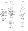
- FIGS. 10 to 15 The embodiment shown in FIGS. 10 to 15 is constructed essentially according to the same principle, but adapted to a square key 146, as shown in FIG. 11.
- this key 146 When this key 146 is inserted, its front end first pierces the sheet metal cap 56 placed around the key catch 14 and holding the mask 144, then engages the locking element 122 in a sliding manner and at the same time engages around the prismatic end 138 of the locking core 120 (see FIGS. 12 and 15).
- the key moves the locking element 122 downward and in doing so presses the projections 136 of the locking element 122 out of corresponding grooves 162 of the mask profile of the mask 144, see FIG. 14.
Landscapes
- Engineering & Computer Science (AREA)
- Mechanical Engineering (AREA)
- Power Engineering (AREA)
- Lock And Its Accessories (AREA)
- Casings For Electric Apparatus (AREA)
- Quick-Acting Or Multi-Walled Pipe Joints (AREA)
Priority Applications (4)
| Application Number | Priority Date | Filing Date | Title |
|---|---|---|---|
| AT84111169T ATE36185T1 (de) | 1983-05-07 | 1984-09-19 | Steckschluesselbetaetigbarer, arretierbarer vorreiberverschluss. |
| DE8484111169T DE3473169D1 (en) | 1983-05-07 | 1984-09-19 | Key-operated rotary latch having blocking means |
| AT85104693T ATE39377T1 (de) | 1983-05-07 | 1985-04-18 | Steckschluesselbetaetigbarer vorreiberverschluss. |
| DE8585104693T DE3566918D1 (en) | 1983-05-07 | 1985-04-18 | Socket wrench actuated casement fastener |
Applications Claiming Priority (1)
| Application Number | Priority Date | Filing Date | Title |
|---|---|---|---|
| DE3316834A DE3316834C3 (de) | 1983-05-07 | 1983-05-07 | Betätigungsdorn zur Lagerung in einem Verschlußgehäuse für einen Türverschluß für einen Schaltschrank |
Publications (2)
| Publication Number | Publication Date |
|---|---|
| EP0175012A1 true EP0175012A1 (fr) | 1986-03-26 |
| EP0175012B1 EP0175012B1 (fr) | 1988-08-03 |
Family
ID=6198490
Family Applications (2)
| Application Number | Title | Priority Date | Filing Date |
|---|---|---|---|
| EP84111169A Expired EP0175012B1 (fr) | 1983-05-07 | 1984-09-19 | Verrou rotatif avec moyen d'arrêt, actionné par une clé |
| EP85104693A Expired EP0175049B1 (fr) | 1983-05-07 | 1985-04-18 | Tourniquet susceptible d'être manoeuvré par une clé à tube |
Family Applications After (1)
| Application Number | Title | Priority Date | Filing Date |
|---|---|---|---|
| EP85104693A Expired EP0175049B1 (fr) | 1983-05-07 | 1985-04-18 | Tourniquet susceptible d'être manoeuvré par une clé à tube |
Country Status (3)
| Country | Link |
|---|---|
| EP (2) | EP0175012B1 (fr) |
| AT (2) | ATE36185T1 (fr) |
| DE (5) | DE3316834C3 (fr) |
Cited By (8)
| Publication number | Priority date | Publication date | Assignee | Title |
|---|---|---|---|---|
| EP0175049A3 (en) * | 1983-05-07 | 1987-03-25 | Dieter Ramsauer | Socket wrench actuated casement fastener |
| DE3942774A1 (de) * | 1989-10-03 | 1991-04-11 | Dieter Ramsauer | Gehaeuse fuer verschluesse, stellhebel, durchfuehrungen oder dgl., zur montage in einem druchbruch einer duennen, elektrisch leitenden wand, wie blechschranktuer oder maschinengehaeusedeckel, insbesondere verschlussgehaeuse mit erdungseinrichtung |
| EP0595455A1 (fr) * | 1992-10-28 | 1994-05-04 | Malcoe Precision Fabrications Limited | Serrure |
| EP0965709A1 (fr) * | 1998-06-18 | 1999-12-22 | Steinbach & Vollmann GmbH & Co. | Verrou rotatif |
| EP1258380A3 (fr) * | 2001-05-16 | 2005-01-19 | Still S.A.R.L. | Verrouillage pour un compartiment de pile |
| US9955600B2 (en) | 2015-02-17 | 2018-04-24 | Watchfire Signs, Llc | Fasteners for use in display structures |
| US10690158B2 (en) | 2016-09-13 | 2020-06-23 | Watchfire Signs, Llc | Technologies for interlocking structures |
| WO2024056124A1 (fr) * | 2022-09-13 | 2024-03-21 | Emka Beschlagteile Gmbh & Co. Kg | Verrou, en particulier verrou quart de tour |
Families Citing this family (8)
| Publication number | Priority date | Publication date | Assignee | Title |
|---|---|---|---|---|
| GB8922021D0 (en) * | 1989-09-29 | 1989-11-15 | Bloxwich Eng | Latch assemblies for vehicle bonnets |
| DE3932939B4 (de) * | 1989-10-03 | 2007-09-20 | Dieter Ramsauer | Mittels Erdungs- und/oder Befestigungsfeder in dem Durchbruch einer Blechwand, wie Schaltschranktür befestigbarer Verschluß |
| DE4436474C2 (de) * | 1994-10-12 | 1996-11-21 | Mueller Jean Ohg Elektrotech | Steckschlüsselbetätigbarer, arretierbarer Vorreiberverschluß |
| DE29615343U1 (de) * | 1996-09-03 | 1998-01-08 | Georg Fritzmeier GmbH & Co., 85655 Großhelfendorf | Drehriegelschloß |
| DE29615837U1 (de) * | 1996-09-11 | 1996-10-31 | Steinbach & Vollmann GmbH & Co., 42579 Heiligenhaus | Verschluß, insbesondere Drehriegel |
| US6615956B1 (en) * | 2002-04-15 | 2003-09-09 | Louis Chuang | Brake and lock device |
| DE20303200U1 (de) | 2003-02-26 | 2003-05-08 | Emka Beschlagteile Gmbh & Co. Kg, 42551 Velbert | Vorreiberverschluß |
| EP3917296B1 (fr) | 2020-05-27 | 2024-07-10 | Hoffman Enclosures, Inc. | Système de fixation pour couvercle de boitier |
Citations (3)
| Publication number | Priority date | Publication date | Assignee | Title |
|---|---|---|---|---|
| US3661001A (en) * | 1970-08-03 | 1972-05-09 | Keystone Consolidated Ind Inc | Key ejector lock |
| US3907348A (en) * | 1973-04-27 | 1975-09-23 | Truth Inc | Security lock |
| EP0036141A1 (fr) * | 1980-03-15 | 1981-09-23 | Dieter Ramsauer | Dispositif d'arrêt actionné par une clé |
Family Cites Families (7)
| Publication number | Priority date | Publication date | Assignee | Title |
|---|---|---|---|---|
| DE7338007U (de) * | 1973-10-23 | 1974-01-17 | Krachten E Gmbh & Co Kg | Vorreiber mit in ein Befestigungsgehäuse eingesetztem Betätigungsdorn und an dem Betätigungsdorn befestigter Schließzunge |
| DE7734597U1 (de) * | 1977-11-11 | 1978-03-02 | Gebr. Happich Gmbh, 5600 Wuppertal | Verriegelungsvorrichtung für Schaltschränke aus Kunststoff |
| DE2919830A1 (de) * | 1978-05-16 | 1979-11-22 | Vynckier N V | Tuerverschluss |
| DE7829824U1 (de) * | 1978-10-06 | 1979-02-08 | Rose-Elektrotechnik Gmbh & Co Kg Elektrotechnische Fabrik, 4952 Porta Westfalica | Schaltschrank |
| GB2042048B (en) * | 1979-01-26 | 1982-11-24 | Unimax Switch Ltd | Keyoperated device |
| DE3316834C3 (de) * | 1983-05-07 | 1997-11-13 | Dieter Ramsauer | Betätigungsdorn zur Lagerung in einem Verschlußgehäuse für einen Türverschluß für einen Schaltschrank |
| DE8427541U1 (de) * | 1984-09-19 | 1985-01-03 | Ramsauer, Dieter, 5620 Velbert | Steckschluesselbetaetigbarer, arretierbarer vorreiberverschluss |
-
1983
- 1983-05-07 DE DE3316834A patent/DE3316834C3/de not_active Expired - Fee Related
-
1984
- 1984-09-19 DE DE8484111169T patent/DE3473169D1/de not_active Expired
- 1984-09-19 EP EP84111169A patent/EP0175012B1/fr not_active Expired
- 1984-09-19 AT AT84111169T patent/ATE36185T1/de active
-
1985
- 1985-04-18 DE DE8511456U patent/DE8511456U1/de not_active Expired
- 1985-04-18 AT AT85104693T patent/ATE39377T1/de not_active IP Right Cessation
- 1985-04-18 DE DE8585104693T patent/DE3566918D1/de not_active Expired
- 1985-04-18 EP EP85104693A patent/EP0175049B1/fr not_active Expired
- 1985-09-17 DE DE8526488U patent/DE8526488U1/de not_active Expired
Patent Citations (3)
| Publication number | Priority date | Publication date | Assignee | Title |
|---|---|---|---|---|
| US3661001A (en) * | 1970-08-03 | 1972-05-09 | Keystone Consolidated Ind Inc | Key ejector lock |
| US3907348A (en) * | 1973-04-27 | 1975-09-23 | Truth Inc | Security lock |
| EP0036141A1 (fr) * | 1980-03-15 | 1981-09-23 | Dieter Ramsauer | Dispositif d'arrêt actionné par une clé |
Cited By (9)
| Publication number | Priority date | Publication date | Assignee | Title |
|---|---|---|---|---|
| EP0175049A3 (en) * | 1983-05-07 | 1987-03-25 | Dieter Ramsauer | Socket wrench actuated casement fastener |
| DE3942774A1 (de) * | 1989-10-03 | 1991-04-11 | Dieter Ramsauer | Gehaeuse fuer verschluesse, stellhebel, durchfuehrungen oder dgl., zur montage in einem druchbruch einer duennen, elektrisch leitenden wand, wie blechschranktuer oder maschinengehaeusedeckel, insbesondere verschlussgehaeuse mit erdungseinrichtung |
| EP0595455A1 (fr) * | 1992-10-28 | 1994-05-04 | Malcoe Precision Fabrications Limited | Serrure |
| EP0965709A1 (fr) * | 1998-06-18 | 1999-12-22 | Steinbach & Vollmann GmbH & Co. | Verrou rotatif |
| EP1258380A3 (fr) * | 2001-05-16 | 2005-01-19 | Still S.A.R.L. | Verrouillage pour un compartiment de pile |
| US9955600B2 (en) | 2015-02-17 | 2018-04-24 | Watchfire Signs, Llc | Fasteners for use in display structures |
| US10690158B2 (en) | 2016-09-13 | 2020-06-23 | Watchfire Signs, Llc | Technologies for interlocking structures |
| US11248637B2 (en) | 2016-09-13 | 2022-02-15 | Watchfire Signs, Llc | Technologies for interlocking structures |
| WO2024056124A1 (fr) * | 2022-09-13 | 2024-03-21 | Emka Beschlagteile Gmbh & Co. Kg | Verrou, en particulier verrou quart de tour |
Also Published As
| Publication number | Publication date |
|---|---|
| DE3566918D1 (en) | 1989-01-26 |
| EP0175012B1 (fr) | 1988-08-03 |
| EP0175049A3 (en) | 1987-03-25 |
| DE3316834C3 (de) | 1997-11-13 |
| EP0175049B1 (fr) | 1988-12-21 |
| DE8526488U1 (de) | 1986-01-23 |
| DE3473169D1 (en) | 1988-09-08 |
| ATE36185T1 (de) | 1988-08-15 |
| ATE39377T1 (de) | 1989-01-15 |
| DE3316834A1 (de) | 1984-11-08 |
| EP0175049A2 (fr) | 1986-03-26 |
| DE3316834C2 (de) | 1994-02-10 |
| DE8511456U1 (de) | 1986-01-23 |
Similar Documents
| Publication | Publication Date | Title |
|---|---|---|
| EP0175012B1 (fr) | Verrou rotatif avec moyen d'arrêt, actionné par une clé | |
| EP1290303B1 (fr) | Serrure a barres pour systeme de fermeture | |
| DE102018202563B4 (de) | Knauf für einen elektronischen Schließzylinder | |
| EP0175211B1 (fr) | Fermeture de tourniquet actionnée et arrêtée au moyen d'une clé à douille | |
| DE2557151A1 (de) | Chlosschutzvorrichtung | |
| EP2796645B1 (fr) | Serrure à pêne dormant d'un meuble | |
| EP4438836B1 (fr) | Système de fermeture et porte ou fenêtre dotée d'un tel système de fermeture | |
| EP0096229B1 (fr) | Serrure pour porte, fenêtre ou analogue | |
| EP0036141B1 (fr) | Dispositif d'arrêt actionné par une clé | |
| EP1723300A1 (fr) | Dispositif de reglage de loquets rotatifs et basculants | |
| DE2339919A1 (de) | Zylinderschloss zum einbau in tueren | |
| EP0270951B1 (fr) | Poignée verrouillable de fenêtre | |
| DE102015121175A1 (de) | Sicherheitsbeschlag für Panikschloss | |
| DE2911647C2 (de) | Zahnradantrieb in einem schließzylinderbetätigbaren Treibstangenschloß | |
| DE3342458C2 (fr) | ||
| EP0585735B1 (fr) | Serrure de fixation pour cylindre d'un verrou de sécurité | |
| DE3510439C2 (de) | Beschlag für Fenster oder Türen | |
| DE9210795U1 (de) | Sicherheitsbeschlag für mit einem Profilschließzylinder versehene Türschlösser | |
| EP1724417B1 (fr) | Élément de serrure | |
| DE2321246C3 (de) | Magnetisch betätigbares Schloß | |
| DE19507481C1 (de) | Abschließbarer Fenstergriff | |
| DE2928032A1 (de) | Tuerdrueckerverbindung fuer eine aus zwei axial einander gegenueberliegenden nusshaelften bestehende schlossnuss | |
| EP1116838A1 (fr) | Ferrure de protection pour porte | |
| DE202011005241U1 (de) | Stangenführung | |
| EP0589209A2 (fr) | Serrure cylindrique |
Legal Events
| Date | Code | Title | Description |
|---|---|---|---|
| PUAI | Public reference made under article 153(3) epc to a published international application that has entered the european phase |
Free format text: ORIGINAL CODE: 0009012 |
|
| AK | Designated contracting states |
Kind code of ref document: A1 Designated state(s): AT BE CH DE FR GB IT LI LU NL SE |
|
| 17P | Request for examination filed |
Effective date: 19860627 |
|
| 17Q | First examination report despatched |
Effective date: 19861128 |
|
| D17Q | First examination report despatched (deleted) | ||
| GRAA | (expected) grant |
Free format text: ORIGINAL CODE: 0009210 |
|
| AK | Designated contracting states |
Kind code of ref document: B1 Designated state(s): AT BE CH DE FR GB IT LI LU NL SE |
|
| PG25 | Lapsed in a contracting state [announced via postgrant information from national office to epo] |
Ref country code: NL Effective date: 19880803 Ref country code: BE Effective date: 19880803 |
|
| REF | Corresponds to: |
Ref document number: 36185 Country of ref document: AT Date of ref document: 19880815 Kind code of ref document: T |
|
| GBT | Gb: translation of ep patent filed (gb section 77(6)(a)/1977) | ||
| REF | Corresponds to: |
Ref document number: 3473169 Country of ref document: DE Date of ref document: 19880908 |
|
| PG25 | Lapsed in a contracting state [announced via postgrant information from national office to epo] |
Ref country code: AT Effective date: 19880919 |
|
| PG25 | Lapsed in a contracting state [announced via postgrant information from national office to epo] |
Ref country code: LU Free format text: LAPSE BECAUSE OF NON-PAYMENT OF DUE FEES Effective date: 19880930 Ref country code: LI Effective date: 19880930 Ref country code: CH Effective date: 19880930 |
|
| ITF | It: translation for a ep patent filed | ||
| ET | Fr: translation filed | ||
| NLV1 | Nl: lapsed or annulled due to failure to fulfill the requirements of art. 29p and 29m of the patents act | ||
| PLBE | No opposition filed within time limit |
Free format text: ORIGINAL CODE: 0009261 |
|
| REG | Reference to a national code |
Ref country code: CH Ref legal event code: PL |
|
| STAA | Information on the status of an ep patent application or granted ep patent |
Free format text: STATUS: NO OPPOSITION FILED WITHIN TIME LIMIT |
|
| 26N | No opposition filed | ||
| PGFP | Annual fee paid to national office [announced via postgrant information from national office to epo] |
Ref country code: SE Payment date: 19900907 Year of fee payment: 7 |
|
| PGFP | Annual fee paid to national office [announced via postgrant information from national office to epo] |
Ref country code: GB Payment date: 19900908 Year of fee payment: 7 |
|
| PGFP | Annual fee paid to national office [announced via postgrant information from national office to epo] |
Ref country code: FR Payment date: 19900928 Year of fee payment: 7 |
|
| ITTA | It: last paid annual fee | ||
| PGFP | Annual fee paid to national office [announced via postgrant information from national office to epo] |
Ref country code: DE Payment date: 19901009 Year of fee payment: 7 |
|
| PG25 | Lapsed in a contracting state [announced via postgrant information from national office to epo] |
Ref country code: GB Effective date: 19910919 |
|
| PG25 | Lapsed in a contracting state [announced via postgrant information from national office to epo] |
Ref country code: SE Effective date: 19910920 |
|
| GBPC | Gb: european patent ceased through non-payment of renewal fee | ||
| PG25 | Lapsed in a contracting state [announced via postgrant information from national office to epo] |
Ref country code: FR Effective date: 19920529 |
|
| PG25 | Lapsed in a contracting state [announced via postgrant information from national office to epo] |
Ref country code: DE Effective date: 19920602 |
|
| REG | Reference to a national code |
Ref country code: FR Ref legal event code: ST |
|
| EUG | Se: european patent has lapsed |
Ref document number: 84111169.3 Effective date: 19920408 |