EP0175236A2 - Dispositif pour l'introduction d'un câble plat - Google Patents
Dispositif pour l'introduction d'un câble plat Download PDFInfo
- Publication number
- EP0175236A2 EP0175236A2 EP85111283A EP85111283A EP0175236A2 EP 0175236 A2 EP0175236 A2 EP 0175236A2 EP 85111283 A EP85111283 A EP 85111283A EP 85111283 A EP85111283 A EP 85111283A EP 0175236 A2 EP0175236 A2 EP 0175236A2
- Authority
- EP
- European Patent Office
- Prior art keywords
- cable
- seal
- housing
- flat cable
- holding part
- Prior art date
- Legal status (The legal status is an assumption and is not a legal conclusion. Google has not performed a legal analysis and makes no representation as to the accuracy of the status listed.)
- Granted
Links
- 238000007373 indentation Methods 0.000 claims abstract description 6
- 238000007789 sealing Methods 0.000 claims description 11
- 238000005452 bending Methods 0.000 claims description 3
- 239000000463 material Substances 0.000 description 5
- 238000003780 insertion Methods 0.000 description 4
- 230000037431 insertion Effects 0.000 description 4
- 238000007639 printing Methods 0.000 description 4
- 241001295925 Gegenes Species 0.000 description 3
- 230000015572 biosynthetic process Effects 0.000 description 3
- 239000000356 contaminant Substances 0.000 description 3
- 239000013013 elastic material Substances 0.000 description 3
- 230000000149 penetrating effect Effects 0.000 description 3
- 230000006978 adaptation Effects 0.000 description 2
- 239000000428 dust Substances 0.000 description 2
- 229920001971 elastomer Polymers 0.000 description 2
- 229920001821 foam rubber Polymers 0.000 description 2
- 210000004907 gland Anatomy 0.000 description 2
- 230000003993 interaction Effects 0.000 description 2
- 238000000465 moulding Methods 0.000 description 2
- 239000003566 sealing material Substances 0.000 description 2
- 229910000831 Steel Inorganic materials 0.000 description 1
- 239000004020 conductor Substances 0.000 description 1
- 238000010276 construction Methods 0.000 description 1
- 238000001746 injection moulding Methods 0.000 description 1
- 238000004519 manufacturing process Methods 0.000 description 1
- 239000002184 metal Substances 0.000 description 1
- 239000004033 plastic Substances 0.000 description 1
- 230000000284 resting effect Effects 0.000 description 1
- 210000002023 somite Anatomy 0.000 description 1
- 239000010959 steel Substances 0.000 description 1
Images




Classifications
-
- H—ELECTRICITY
- H01—ELECTRIC ELEMENTS
- H01R—ELECTRICALLY-CONDUCTIVE CONNECTIONS; STRUCTURAL ASSOCIATIONS OF A PLURALITY OF MUTUALLY-INSULATED ELECTRICAL CONNECTING ELEMENTS; COUPLING DEVICES; CURRENT COLLECTORS
- H01R13/00—Details of coupling devices of the kinds covered by groups H01R12/70 or H01R24/00 - H01R33/00
- H01R13/58—Means for relieving strain on wire connection, e.g. cord grip, for avoiding loosening of connections between wires and terminals within a coupling device terminating a cable
- H01R13/595—Bolts operating in a direction transverse to the cable or wire
-
- H—ELECTRICITY
- H02—GENERATION; CONVERSION OR DISTRIBUTION OF ELECTRIC POWER
- H02G—INSTALLATION OF ELECTRIC CABLES OR LINES, OR OF COMBINED OPTICAL AND ELECTRIC CABLES OR LINES
- H02G3/00—Installations of electric cables or lines or protective tubing therefor in or on buildings, equivalent structures or vehicles
- H02G3/02—Details
- H02G3/06—Joints for connecting lengths of protective tubing or channels, to each other or to casings, e.g. to distribution boxes; Ensuring electrical continuity in the joint
- H02G3/0616—Joints for connecting tubing to casing
- H02G3/0625—Joints for connecting tubing to casing with means for preventing disengagement of conductors
- H02G3/0683—Joints for connecting tubing to casing with means for preventing disengagement of conductors with bolts operating in a direction transverse to the conductors
-
- H—ELECTRICITY
- H02—GENERATION; CONVERSION OR DISTRIBUTION OF ELECTRIC POWER
- H02G—INSTALLATION OF ELECTRIC CABLES OR LINES, OR OF COMBINED OPTICAL AND ELECTRIC CABLES OR LINES
- H02G3/00—Installations of electric cables or lines or protective tubing therefor in or on buildings, equivalent structures or vehicles
- H02G3/22—Installations of cables or lines through walls, floors or ceilings, e.g. into buildings
Definitions
- the invention relates to a device for introducing a flat cable for wall openings, housing walls etc., in particular for connector housings.
- Cable entries must be adequately secured against tensile stress on the cable to prevent the cable from being pulled out of the housing or the cable entry device, respectively, and to prevent unacceptable tensile stresses at the conductor connection points. In addition, it must also be ensured that bending stresses do not damage the cable.
- Cable entries with strain relief for round cables are generally known.
- the cable is fastened in a round through opening using an annular, elastic sealing or clamping element by means of a so-called gland screw connection.
- the sealing element is pressed together by a screwable part, the inside diameter of which is reduced and this is pressed firmly against the cable sheath of the cable passed therethrough.
- a firm hold of the cable in the cable entry and on the other hand a seal against external influences such as dust and moisture is achieved.
- Such gland screw connections are unsuitable for flat cables due to their geometric dimensions.
- the invention is therefore based on the object to provide a cable entry for flat cable which is largely adapted to the dimensions of the flat cable (width / thickness), which offers adequate protection against the ingress of foreign bodies, and in which the cable is secured is present in relation to tensile stresses, with bending stresses of the cable also not leading to damage to the inserted cable.
- a frame-shaped mounting part is provided, which is provided with posts arranged on opposite sides, a cable passage facing the interior of the housing being provided in the bottom region of the mounting part, a molding with edge-side support shoulders for an insertable, Elastic seal is formed, the seal is provided with a through-opening corresponding to the cross-sectional shape of the flat cable, and wherein the strain relief bracket can be screwed to the posts of the holding part with the interposition of the flat cable.
- the advantages achieved by the invention are, in particular, that a flat cable entry with strain relief and simultaneous sealing was created, which is largely adapted to the cross-sectional shape of the flat cable and has a minimal expansion in the transverse direction of the flat cable cross-section.
- the cable entry can be used particularly advantageously on narrow, rectangular connector housings or housings in general.
- such a cable entry at line entries / cable connections can be changed in devices such as Trolleys or the like, in which shifting movements occur continuously during operation, are used.
- the embodiment according to claim 8 or 9 enables not only one, but also several in a device for cable entry. parallel, "stacked" flat cables can be introduced.
- the embodiment according to claim 9 is particularly advantageous with regard to manufacturing and storage costs, since a uniform cable entry can be used for all occurring cable arrangements or numbers, which is provided with a correspondingly large-sized cable passage opening.
- the adaptation to the cable configuration used in each case can be done by means of differently designed, inexpensive seals in connection with pressure washers.
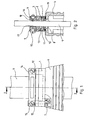
- the flat cable entry with strain relief shown in FIGS. 1 and 2 consists essentially of a frame-shaped mounting part 1, a seal 2, a pressure plate 3, and the strain relief bracket 4 and 5.
- the holding part is provided on a plug connector housing 6 and is fastened to the flat cable 9 by means of the screws 7 via a through opening 8 for the flat cable 9 to be inserted.
- An elastic seal 2 is inserted into the holder part 1. the seal resting on the bottom of the mounting part on the support shoulders 10 provided here. is laterally surrounded by the side parts 11 of the mounting part and tightly encloses the flat cable.
- the pressure plate 3 is provided over the seal. which is screwed to the mounting part by means of the screws 12 and the circumferential, bead-shaped edge 13 of which is pressed against the seal.
- the bracket part 1 is further provided with two vertical, side posts 14 to which the strain relief bracket 4, 5 are attached.
- one of the two brackets is provided with threaded holes and the posts and the other bracket are each equipped with through openings for the screws 15.
- the bracket 4 is provided with a rib 16 running transversely to the cable and the bracket 5 is provided with two ribs 17 which are in question. Corresponding curves on the ribs prevent damage to the cable, the edges 18 of the brackets pointing outward toward the outgoing cable also being rounded in order to prevent damage to the cable when it is bent.
- strain relief brackets 4, 5 are brought into position and screwed together.
- the flat cable guided between the brackets is firmly clamped and held securely, the brackets being firmly connected to the posts of the holding part at the same time. .
- the strain relief of the inserted flat cable is achieved on the one hand and, on the other hand, adequate sealing of the interior of the housing against penetrating contaminants such as dust. Moisture etc. achieved.
- the flat cable entry according to the invention can be used on all flat housing or wall surfaces. It is intended for widely different flat cable dimensions (widths / thicknesses). that seals and pressure plates are used with correspondingly different openings (adapted to the cables used in each case). Provision can also be made for two or, if necessary, also a plurality of flat cables to be introduced one above the other into the cable entry, with adapted seals and pressure plates also being used here. likewise sealing of the insertion point is achieved by pressing the seal against the outer cable and pressing the cable itself against one another.
- the pressure plate can be omitted and the seal must be dimensioned so thick. that it protrudes slightly beyond the side parts 11 of the bracket part.
- the strain relief clamps are then to be designed in this way, however. that their undersides press on the seal when screwing to the posts of the mounting part.
- the underside of the bracket can additionally be provided with a strip-like formation - similar to the bead-shaped edge of the pressure plate.
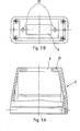
- FIGS. 3 to 8 For a better understanding of the design of the various elements of the flat cable entry and their interaction, these are shown separately in FIGS. 3 to 8 and are briefly explained below.
- the connector housing 6 is shown, which is provided on its upper side with a rectangular through-opening 8 for the flat cable to be inserted. In addition to the opening, through holes 20 are provided for the screw fastening of the holding part 1. Otherwise, the connector housing corresponds to a commercially known housing, into which a connector insert (not shown here) can be inserted from the underside.
- the holding part consists essentially of a frame-shaped base part 21, which is provided on two opposite sides with two posts 14.
- the base part is provided with a rectangular indentation 22, the side parts 11 of the holding part being formed.
- a rectangular opening 23 is provided for the flat cable to be passed through. This opening is smaller than the clear width of the indentation 22, so that here the support shoulders 10 are formed for the seal 2 to be inserted later.
- a circumferential groove 24 is formed on the underside of the holding part, into which - as described above - a sealing ring 19 can be inserted.
- the posts 14 are provided in their upper region with holes 25 which are used to fasten the strain relief brackets 4, 5.
- Threaded bores 26 are provided for attachment to the connector housing 6 or a wall surface.
- the threaded bores 27 provided in the top of the holding frame serve to fasten the pressure plate 3.
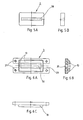
- the seal 2 is shown.
- the seal is made of elastic material, preferably foam rubber.
- the outer dimensions are designed in accordance with the dimensions of the indentation 22 of the holding part and the thickness of the seal corresponds approximately to the depth of this indentation. At least the seal is to be made so thick that sufficient sealing material is available when compressed by the pressure plate, which material can "flow" in the transverse direction of the seal.
- the seal is provided with a central, rectangular opening 28, the width (length / width) of which is designed in accordance with the flat cable used.
- Fig. 6 shows the design of the printing plate 3.
- the printing plate is essentially a flat, rectangular, the shape (in relation to the outer dimensions) of the mounting part adapted.
- lateral slots 29 are provided for receiving the posts 14 of the mounting part.
- the pressure plate is provided with a rectangular opening 30, which is also adapted to the flat cable to be inserted.
- the opening is surrounded by a circumferential, bead-shaped edge 13 which presses on the seal 2 when the cable entry is assembled.
- Bores 31 are provided for fastening to the mounting part.
- FIGS. 7 and 8 show the design of the strain relief brackets 4 and 5. As already mentioned above, these brackets are screwed against one another with the interposition of the flat cable.
- the rigid bracket 4 is provided with a transverse rib 16, while the rigid bracket 5 is also provided with two spaced ribs 17.
- brackets are provided with bores 32, 33 for mutual screwing, including the posts 14 of the holding part, through bores 33 being provided in one bracket and threaded bores 32 being provided in the other bracket.
- edges of the ribs and the bracket itself that come into contact with the cable are rounded off to prevent damage to the cable.
- one of the two brackets is formed in one piece with the posts 14 of the mounting part 1.
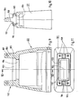
- a connector housing 101 is shown in different views.
- a frame-shaped holding part 102 is provided, which is formed in one piece with the housing.
- the housing with the holding part consists of metal or plastic material and is preferably produced by injection molding.
- a substantially rectangular recess 103 is formed in the holding part, in the bottom region of which a rectangular through-opening 104 is arranged, which leads to the interior of the housing.
- the dimensions of this passage opening are smaller than that of the recess 103, so that here the edge; circumferential shoulders 105 are formed.
- Vertical posts 106 are provided on two opposite sides of the mounting part, to which the strain relief bracket described below can be attached.
- corresponding bores 107 are provided in the posts.
- threaded bores 108 are provided in the mounting part, which are used to fasten a pressure plate, which may be provided and is also described in more detail below.
- a connector insert, not shown here, can be mounted in the housing on the housing side opposite the holding part.
- FIGS. 12 and 13 in which is shown. as a flat cable 109 is inserted into the housing 101 and held strain relieved.
- the recess 103 of the holding part 102 is one made of elastic material. such as soft rubber. Foam rubber or similar Material.
- existing seal 110 inserted - The seal is in its outer dimensions according to the dimension the recess 103 is formed. with one corresponding to the cross-sectional shape of the flat cable. rectangular. middle slot 122 provided.
- a pressure disk 111, 111 'made of rigid material (for example steel sheet) is arranged on the top and bottom of the seal. The outer dimensions of these disks correspond to the geometry of the recess 103 of the holding part and are provided with a central opening which corresponds to the cross-sectional dimension of the inserted flat cable 109.
- the flat cable is guided through the slot 122 of the seal and the opening 128 of the disks and projects through the through opening 104 into the interior of the housing.
- a pressure plate 112 is also pushed over the cable and screwed to the holding part by means of the screws 113 which are screwed into the bores 108.
- a circumferential, bead-shaped edge 114 of the pressure plate presses on the upper disk 111, the seal being pressed together. Due to the side parts 115 of the mounting part that enclose the seal laterally / externally, the seal cannot deflect outwards and thus strives towards the inside. to dodge towards the cable. The seal is pressed firmly against the flat cable on all sides.
- the lower disc 111 'rests on the edges (shoulders 105) of the holding part and causes it. that the elastic seal is not pushed through the through opening 104, which is preferably larger (for the insertion of several parallel flat cables). Overall, with such a construction of the cable entry, a perfect seal against penetrating foreign bodies and moisture is achieved.
- strain relief brackets 116, 117 are provided, which are screwed to the posts 106 of the holding part with the interposition of the flat cable.
- one of the two brackets is provided with threaded holes and the posts and the other bracket are each provided with through openings for the screws 118.
- the bracket 116 When screwing the two brackets together, the flat cable is clamped between them and held securely.
- the bracket 116 is provided with a rib 119 running transversely to the cable and the bracket 117 is provided with two spaced-apart ribs 120.
- the rib 119 of the bracket 116 is centered between the two ribs 120 of the bracket 117.
- Corresponding curves on the ribs prevent damage to the cable, the edges 121 of the cable pointing outwards towards the outgoing cable Brackets are rounded to avoid damage to the cable when it is bent.
- the flat cable entry according to the invention is not only to be used in connector housings which are each manufactured for a specific cable dimension, and then passage openings 104 in the holding part, which are designed in accordance with the cable cross section, and different seals and pressure plates provided with corresponding slots are used.
- a housing adapted to the respective cable cross section however, no pressure disks 111, 111 'need be provided, since a perfect seal can be achieved even without these disks.
- the connector housing is preferably provided. That - as shown in FIGS. 9-13 - the opening 104 in the mounting part / housing is so large that the maximum number of flat cables provided can be inserted one on top of the other.
- FIG. 13 A A corresponding arrangement is shown in FIG. 13 A, the insertion and holding of three flat cables 109, 109 1 , 109 "being shown here.
- the housing with the flat cable insertion opening 104 for the maximum number of flat cables, this can be done there is no need to insert pressure washers, as the seal cannot escape without these washers and the cable entry is properly sealed, with the cables lying flat on top of each other are pressed.
- the pressure disks 111, 111 ' are inserted, as already explained above, and a perfect seal is then also achieved here.
- the advantage of this embodiment is that the use of a uniform standard housing, the adaptation to the different cable numbers or dimensions being carried out by inexpensive pressure disks and seals with only different openings 128.
- the pressure plate is also omitted and the seal is dimensioned so thick that it protrudes somewhat over the side parts 115 of the mounting part.
- the strain relief bracket must then be designed so that their undersides press on the seal when screwed to the posts of the mounting part.
- the underside of the bracket can additionally be provided with a strip-like formation - similar to the bead-shaped edge of the pressure plate.
- the seal is made of elastic material, preferably soft rubber.
- the external dimensions are designed in accordance with the dimensions of the recess 103 of the holding part and the thickness of the seal corresponds approximately to the depth of this recess. At least the seal should be made so thick that it can be compressed by the pressure plate enough sealing material is available that can "flow" in the transverse direction of the seal.
- the seal is provided with a central, rectangular opening (slot 122), the width (length / width) of which is designed in accordance with the flat cable used, possibly up to the size indicated by dash-dotted lines.
- 15 A. 15 B shows the formation of a thrust washer 111. 111 'which essentially corresponds to the shape of the seal shown in FIG. 14 A. 14 B. however thinner and made of rigid material.
- the pressure plate is essentially a flat one. rectangular. plate adapted to the shape (in relation to the external dimensions) of the mounting part, lateral slots 123 being provided for receiving the posts 106 of the mounting part.
- the pressure plate is provided with a rectangular opening 124, which is also adapted to the flat cable to be inserted. The opening is surrounded by a circumferential, bead-shaped edge 114 which presses on the seal 110 or washer 111 when the cable entry is assembled. Bores 125 are provided for fastening to the mounting part.
- strain relief brackets are used in this embodiment, too, which are designed and arranged in accordance with those of the first exemplary embodiment, as described for FIGS. 7 and 8.
Landscapes
- Engineering & Computer Science (AREA)
- Architecture (AREA)
- Civil Engineering (AREA)
- Structural Engineering (AREA)
- Connector Housings Or Holding Contact Members (AREA)
- Installation Of Indoor Wiring (AREA)
- Insertion, Bundling And Securing Of Wires For Electric Apparatuses (AREA)
Priority Applications (1)
| Application Number | Priority Date | Filing Date | Title |
|---|---|---|---|
| AT85111283T ATE50472T1 (de) | 1984-09-19 | 1985-09-06 | Vorrichtung zur einfuehrung eines flachkabels. |
Applications Claiming Priority (4)
| Application Number | Priority Date | Filing Date | Title |
|---|---|---|---|
| DE19848427559 DE8427559U1 (de) | 1984-09-19 | 1984-09-19 | Flachkabeleinführung mit Zugentlastung |
| DE8427559U | 1984-09-19 | ||
| DE8511822U | 1985-04-20 | ||
| DE19858511822 DE8511822U1 (de) | 1985-04-20 | 1985-04-20 | Flachkabeleinführung mit Zugentlastung |
Publications (3)
| Publication Number | Publication Date |
|---|---|
| EP0175236A2 true EP0175236A2 (fr) | 1986-03-26 |
| EP0175236A3 EP0175236A3 (en) | 1987-04-29 |
| EP0175236B1 EP0175236B1 (fr) | 1990-02-21 |
Family
ID=25950038
Family Applications (1)
| Application Number | Title | Priority Date | Filing Date |
|---|---|---|---|
| EP85111283A Expired - Lifetime EP0175236B1 (fr) | 1984-09-19 | 1985-09-06 | Dispositif pour l'introduction d'un câble plat |
Country Status (3)
| Country | Link |
|---|---|
| US (1) | US4634206A (fr) |
| EP (1) | EP0175236B1 (fr) |
| DE (1) | DE3576101D1 (fr) |
Cited By (4)
| Publication number | Priority date | Publication date | Assignee | Title |
|---|---|---|---|---|
| EP0250849A3 (fr) * | 1986-06-23 | 1989-11-29 | Tektronix, Inc. | Dispositif de serre-câble |
| EP0695900A1 (fr) * | 1994-08-02 | 1996-02-07 | France Telecom | Passage étanche pour câble de télécommunications |
| DE202011000707U1 (de) | 2011-03-29 | 2011-09-07 | Zellner Gmbh | Fluiddichte Zugentlastung |
| EP3598593A1 (fr) | 2018-07-21 | 2020-01-22 | Lapp Engineering & Co. | Presse-étoupe |
Families Citing this family (4)
| Publication number | Priority date | Publication date | Assignee | Title |
|---|---|---|---|---|
| US4840581A (en) * | 1988-12-22 | 1989-06-20 | Amp Incorporated | Cable jacket strain relief adapter assembly |
| US6551124B1 (en) | 1999-09-20 | 2003-04-22 | Woertz Ag | Contacting device for a flat band cable |
| EP3525304B1 (fr) * | 2018-02-08 | 2022-04-27 | Aptiv Technologies Limited | Passe-câble, élément électronique et procédé de formation d'un passe-câble |
| CN118712818B (zh) * | 2024-08-30 | 2024-11-29 | 四川准达信息技术股份有限公司 | 一种光伏储能电站输送电缆连接装置 |
Citations (1)
| Publication number | Priority date | Publication date | Assignee | Title |
|---|---|---|---|---|
| DE8135327U1 (de) | 1980-12-12 | 1982-04-22 | Inventio AG, 6052 Hergiswil, Nidwalden | Kabelverschraubung für Flachkabel |
Family Cites Families (8)
| Publication number | Priority date | Publication date | Assignee | Title |
|---|---|---|---|---|
| US2963536A (en) * | 1956-09-27 | 1960-12-06 | Bendix Corp | Clamping and sealing device |
| GB1209445A (en) * | 1966-12-28 | 1970-10-21 | Plessey Co Ltd | Improvements in or relating to strain-relieving cable clamps |
| US3568131A (en) * | 1969-11-26 | 1971-03-02 | Bobby W Kennedy | Electrical connector |
| DE7124862U (de) * | 1971-06-29 | 1971-09-30 | Kalthoff A | Zugentlastung für ein in ein Gehäuse eines Steckers oder dgl. Einrichtung einzuführendes Kabel |
| DE3128541A1 (de) * | 1981-07-18 | 1983-02-03 | Harting Elektronik Gmbh, 4992 Espelkamp | Kabelverschraubung mit sicherung gegen unbeabsichtigtes loesen |
| US4451099A (en) * | 1982-05-07 | 1984-05-29 | Amp Incorporated | Electrical connector having commoning member |
| US4537458A (en) * | 1983-09-01 | 1985-08-27 | Continental-Wirt Electronics Corp. | Conductive shielding housing for flat cable connector |
| DE8332294U1 (de) * | 1983-11-10 | 1984-02-02 | Elektro-Apparate KG Gothe & Co, 4330 Mülheim | Kabeleinführungsstutzen für explosionsgeschützte elektrische Einrichtungen |
-
1985
- 1985-09-04 US US06/772,595 patent/US4634206A/en not_active Expired - Lifetime
- 1985-09-06 EP EP85111283A patent/EP0175236B1/fr not_active Expired - Lifetime
- 1985-09-06 DE DE8585111283T patent/DE3576101D1/de not_active Expired - Lifetime
Patent Citations (1)
| Publication number | Priority date | Publication date | Assignee | Title |
|---|---|---|---|---|
| DE8135327U1 (de) | 1980-12-12 | 1982-04-22 | Inventio AG, 6052 Hergiswil, Nidwalden | Kabelverschraubung für Flachkabel |
Cited By (6)
| Publication number | Priority date | Publication date | Assignee | Title |
|---|---|---|---|---|
| EP0250849A3 (fr) * | 1986-06-23 | 1989-11-29 | Tektronix, Inc. | Dispositif de serre-câble |
| EP0695900A1 (fr) * | 1994-08-02 | 1996-02-07 | France Telecom | Passage étanche pour câble de télécommunications |
| FR2723419A1 (fr) * | 1994-08-02 | 1996-02-09 | Crespel Daniel | Dispositif pour passage etanche pour cables ou analogues |
| DE202011000707U1 (de) | 2011-03-29 | 2011-09-07 | Zellner Gmbh | Fluiddichte Zugentlastung |
| EP2506375A2 (fr) | 2011-03-29 | 2012-10-03 | Zellner GmbH | Fixation étanche résistante à la traction pour objets ronds oblongs |
| EP3598593A1 (fr) | 2018-07-21 | 2020-01-22 | Lapp Engineering & Co. | Presse-étoupe |
Also Published As
| Publication number | Publication date |
|---|---|
| DE3576101D1 (de) | 1990-03-29 |
| US4634206A (en) | 1987-01-06 |
| EP0175236B1 (fr) | 1990-02-21 |
| EP0175236A3 (en) | 1987-04-29 |
Similar Documents
| Publication | Publication Date | Title |
|---|---|---|
| EP0284889A2 (fr) | Armoire de commutation avec conditionneur d'air | |
| EP0618656A1 (fr) | Dispositif pour traversée de cables | |
| EP2928034A1 (fr) | Passage de câble | |
| EP0175236B1 (fr) | Dispositif pour l'introduction d'un câble plat | |
| EP0792094A1 (fr) | Dispositif de commande électronique | |
| DE10334518A1 (de) | Kabelabdichtung für einen Steckverbinder | |
| DE19604219C1 (de) | Kabeleinführung für einen Schaltschrank | |
| EP0838879B1 (fr) | Boîtier de connecteur à fiche blindé contre les intérférences électromagnétiques | |
| DE3903488C1 (fr) | ||
| DE2633187C3 (de) | Gehäuse zur Aufnahme von elektrotechnischen oder elektronischen Geräten mit einer Vielfach-Kabelabdichtung und -Kabelzugentlastung | |
| DE19723032C1 (de) | Abgedichtete Kabeleinführung | |
| DE8511822U1 (de) | Flachkabeleinführung mit Zugentlastung | |
| WO2000015996A1 (fr) | Collier de tube ou de cable electroconducteur | |
| DE3504726C1 (de) | Abschirmgehäuse für Hochfrequenz-Dünnschichtschaltungen | |
| DE3815032A1 (de) | Terminalgehaeuse | |
| DE29618628U1 (de) | Abgeschirmter Baugruppenträger | |
| DE2915109C2 (de) | Näherungsinitiator | |
| DE2255785A1 (de) | Einrichtung zum anschluss eines koaxialkabels | |
| DE8427559U1 (de) | Flachkabeleinführung mit Zugentlastung | |
| DE69602670T2 (de) | Verbinder, Gehäuse davon und metallische Haube davon | |
| DE19851590C1 (de) | Baugruppenträger | |
| EP0593846A2 (fr) | Boîtier étanche | |
| DE29507446U1 (de) | Abdeckplatte | |
| CH653511A5 (de) | Klemmvorrichtung mit einem gehaeuse und einer klemmleiste fuer eine mit einer gedruckten schaltung versehenen platine. | |
| DE2752763B2 (de) | Endverzweiger für Fernmeldekabel |
Legal Events
| Date | Code | Title | Description |
|---|---|---|---|
| PUAI | Public reference made under article 153(3) epc to a published international application that has entered the european phase |
Free format text: ORIGINAL CODE: 0009012 |
|
| AK | Designated contracting states |
Kind code of ref document: A2 Designated state(s): AT BE CH DE FR GB IT LI NL SE |
|
| PUAL | Search report despatched |
Free format text: ORIGINAL CODE: 0009013 |
|
| AK | Designated contracting states |
Kind code of ref document: A3 Designated state(s): AT BE CH DE FR GB IT LI NL SE |
|
| 17P | Request for examination filed |
Effective date: 19870905 |
|
| 17Q | First examination report despatched |
Effective date: 19890309 |
|
| GRAA | (expected) grant |
Free format text: ORIGINAL CODE: 0009210 |
|
| AK | Designated contracting states |
Kind code of ref document: B1 Designated state(s): AT BE CH DE FR GB IT LI NL SE |
|
| REF | Corresponds to: |
Ref document number: 50472 Country of ref document: AT Date of ref document: 19900315 Kind code of ref document: T |
|
| ITF | It: translation for a ep patent filed | ||
| ET | Fr: translation filed | ||
| REF | Corresponds to: |
Ref document number: 3576101 Country of ref document: DE Date of ref document: 19900329 |
|
| GBT | Gb: translation of ep patent filed (gb section 77(6)(a)/1977) | ||
| PG25 | Lapsed in a contracting state [announced via postgrant information from national office to epo] |
Ref country code: GB Effective date: 19900906 |
|
| PG25 | Lapsed in a contracting state [announced via postgrant information from national office to epo] |
Ref country code: SE Effective date: 19900907 |
|
| PG25 | Lapsed in a contracting state [announced via postgrant information from national office to epo] |
Ref country code: LI Effective date: 19900930 Ref country code: CH Effective date: 19900930 Ref country code: BE Effective date: 19900930 |
|
| PLBE | No opposition filed within time limit |
Free format text: ORIGINAL CODE: 0009261 |
|
| STAA | Information on the status of an ep patent application or granted ep patent |
Free format text: STATUS: NO OPPOSITION FILED WITHIN TIME LIMIT |
|
| 26N | No opposition filed | ||
| BERE | Be: lapsed |
Owner name: HARTING ELEKTRONIK G.M.B.H. Effective date: 19900930 |
|
| PG25 | Lapsed in a contracting state [announced via postgrant information from national office to epo] |
Ref country code: NL Effective date: 19910401 |
|
| GBPC | Gb: european patent ceased through non-payment of renewal fee | ||
| NLV4 | Nl: lapsed or anulled due to non-payment of the annual fee | ||
| REG | Reference to a national code |
Ref country code: CH Ref legal event code: PL |
|
| ITTA | It: last paid annual fee | ||
| PGFP | Annual fee paid to national office [announced via postgrant information from national office to epo] |
Ref country code: FR Payment date: 19920904 Year of fee payment: 8 Ref country code: AT Payment date: 19920904 Year of fee payment: 8 |
|
| PG25 | Lapsed in a contracting state [announced via postgrant information from national office to epo] |
Ref country code: AT Effective date: 19930906 |
|
| PG25 | Lapsed in a contracting state [announced via postgrant information from national office to epo] |
Ref country code: FR Free format text: LAPSE BECAUSE OF NON-PAYMENT OF DUE FEES Effective date: 19940531 |
|
| REG | Reference to a national code |
Ref country code: FR Ref legal event code: ST |
|
| EUG | Se: european patent has lapsed |
Ref document number: 85111283.9 Effective date: 19910527 |
|
| PGFP | Annual fee paid to national office [announced via postgrant information from national office to epo] |
Ref country code: DE Payment date: 20040917 Year of fee payment: 20 |