EP0175246A2 - Dispositif de blocage d'une ceinture - Google Patents
Dispositif de blocage d'une ceinture Download PDFInfo
- Publication number
- EP0175246A2 EP0175246A2 EP85111337A EP85111337A EP0175246A2 EP 0175246 A2 EP0175246 A2 EP 0175246A2 EP 85111337 A EP85111337 A EP 85111337A EP 85111337 A EP85111337 A EP 85111337A EP 0175246 A2 EP0175246 A2 EP 0175246A2
- Authority
- EP
- European Patent Office
- Prior art keywords
- belt
- blocking device
- retractor
- webbing
- clamping device
- Prior art date
- Legal status (The legal status is an assumption and is not a legal conclusion. Google has not performed a legal analysis and makes no representation as to the accuracy of the status listed.)
- Withdrawn
Links
Images



Classifications
-
- B—PERFORMING OPERATIONS; TRANSPORTING
- B60—VEHICLES IN GENERAL
- B60R—VEHICLES, VEHICLE FITTINGS, OR VEHICLE PARTS, NOT OTHERWISE PROVIDED FOR
- B60R22/00—Safety belts or body harnesses in vehicles
- B60R22/34—Belt retractors, e.g. reels
- B60R22/36—Belt retractors, e.g. reels self-locking in an emergency
- B60R22/42—Belt retractors, e.g. reels self-locking in an emergency having means for acting directly upon the belt, e.g. by clamping or friction
Definitions
- the invention relates to a self-locking belt blocking device, in particular for motor vehicles, with a three-point seat belt with a self-locking belt retractor fastened to a vehicle body part, which has at least one belt-strap-sensitive blocking system for blocking the belt winding shaft, and with a clamping device for the belt strap arranged between belt retractor and an upper deflection fitting .
- Such generic belt blocking devices are based on a self-locking belt retractor, as described for example in DE-OS 28 23 334.
- a belt retractor has at least one belt system sensitive locking system, so that the belt winding shaft is blocked at least by rapid pulling on the belt belt.
- a radially deflectable locking member is positively mounted on the belt winding shaft, which at
- the webbing-sensitive blocking namely when the webbing is pulled out too quickly or suddenly, due to its radial deflection controlled by the webbing-sensitive inertia disc, engages in a correspondingly arranged toothing fixed to the housing and thus prevents further rotation of the webbing take-up shaft.
- the inertia disc due to its coupling to the locking member, ensures that the locking member is guided without stops within the toothing fixed to the housing.
- a belt retractor of this type generally works together with a clamping device for the belt webbing in that a further pull on the belt webbing additionally triggers the clamping effect of the clamping device after the belt retractor has been blocked.
- the webbing is deflected by the clamping device coming from the belt retractor between a toothing fixed to the housing and a radially displaceable counter-toothed corrugating roller such that, when the belt webbing is pulled, the corrugating roller is displaced and pressed against the toothing fixed to the housing until the belt strap is completely clamped.
- Switching on the clamping device causes the so-called film reel effect to be switched off, which is explained by the fact that the belt wound in more or less dense windings on the belt winding shaft could be wound much tighter using the appropriate forces, with the result that after blocking the belt winding shaft initially once a compression of the belt reel on the shaft with the corresponding release on webbing.
- the downstream clamping device also responds and the belt webbing holds, this disadvantageous effect of the release on the belt webbing due to the film reel effect is avoided.
- the invention has for its object to improve a belt blocking device of the type mentioned so that the belt blocking device remains functional even after the webbing has been quickly pulled into the belt retractor with the lock tongue on the deflection fitting and the seat belt can then be put on again.
- the axis of the movable corrugating roller is preloaded by means of a spring designed in such a way that the energy of the abruptly braked belt winding mass is not sufficient, to operate the corrugating roller and thus the clamping device.
- the actuation path of the corrugating roller is larger than the unlocking path in the belt retractor, due to the dimension of the elongated hole leading the axis of the corrugating roller and / or the choice of the lever arm with which the belt pull-out force acts on the pivot point of the corrugating roller It is necessary to turn back the inertia washer and remove the locking element from the gear teeth.
- the prevention of the caulking effect is directed towards the formation of the connection between the inertia disc and the locking member, in that the pin or pins of the pin-slot connection coupling the components to one another are chamfered on their side facing the direction of rotation when the belt is pulled out, at the same time the cooperating surface of the recess in the locking member is provided with a corresponding bevel.
- the invention has the advantage that the locking of the locking system of the belt retractor caused by rapid belt retraction and stop of the lock tongue on the deflection fitting can either be released again by pulling on the belt strap without the clamping device responding, or that such a locking in the belt retractor by the movement sequence in the belt retractor without Doing yourself cancels itself again, whereby a locking of the belt blocking device is avoided overall.
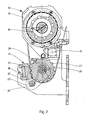
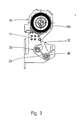
- the belt blocking device consists of a self-locking belt retractor 10, on the housing 11 of which a clamping device 12 is attached.
- the self-locking belt retractor 10 is shown with the cover cap removed, so that its so-called system side is visible.
- FIGS. 1 and 2 show in detail the inertia disk 13 with its external toothing 14, the vehicle-sensitive sensor 15 interacting therewith and the g-value spring 16 acting on the inertia disk 13.
- the locking member Under the inertia disc 13 on the shaft 17 of the belt retractor 10, the locking member is not visible, which can be deflected radially by the inertia disc 13 until it engages in the likewise not visible toothing of a pressure ring 18.
- the structure and mode of operation of such a belt retractor result from the description given in DE-OS 28 34 334.
- the belt webbing 19 is guided in the form of a downward loop through the clamping device 12, which consists of a roller 20, which serves as the sole deflection of the belt webbing 19 and is provided with external teeth 21, and a clamping piece 22 arranged on the housing 11 with a corresponding one There is toothing 23, the belt webbing 19 being guided between the corrugating roller 20 and the clamping piece 22 and the corrugating roller 20 being guided around the half of the side in an upward direction in the direction of the deflection fitting (not shown) for the belt webbing.
- the clamping device 12 which consists of a roller 20, which serves as the sole deflection of the belt webbing 19 and is provided with external teeth 21, and a clamping piece 22 arranged on the housing 11 with a corresponding one There is toothing 23, the belt webbing 19 being guided between the corrugating roller 20 and the clamping piece 22 and the corrugating roller 20 being guided around the half of the side in an upward direction in the direction of the deflection fitting (not shown) for the belt webbing.
- the corrugated roller 20 is displaceably mounted in an elongated hole 24, which has an approximately bean-shaped shape such that the roller 20 passes through a curve section in the direction of the clamping piece 22 when it is displaced.
- the roller In its rest position, the roller is held by an essentially S-shaped bow spring 25, which is attached at one end to the housing 11 and acts at the other end on the shaft of the roller 20, a pin arranged below the roller arrangement on the housing 11 26 acts as a deflection point for the spring 25 and as an ideal fulcrum for the pivoting movement of the roller 20 in the slot 24.
- a bracket 27 is pivotally arranged, which comprises the shaft end of the corrugating roller 20 and carries a locking web 28 on an arm reaching tangentially upwards past the corrugating roller, which is located outside the circumferential toothing 21 of the corrugating roller 20 when the corrugating roller 20 is at rest.
- the bracket 27 has the task of controlling the clamping process and of preventing tooth-on-tooth blocking of the peripheral toothing 21 of the roller 20 with the associated toothing 23 of the clamping piece 22, as will be explained elsewhere.
- the spring 25 is now designed such that the energy of the abruptly braked belt winding on the belt winding shaft 17 is not sufficient to actuate the clamping device, in particular thus to lift the corrugated roller 20 out of its rest position.
- the belt retractor 10 is briefly blocked in the manner described at the outset, but this blockage can still be released again by a strong pull on the belt strap 19, since the clamping device is still free.
- as much belt webbing can first be pulled out of the belt retractor 10 in order to release the blocking of the belt retractor 10 again.
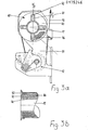
- spring tongues 41 are arranged on the inside of the film spool 40 arranged on the belt take-up shaft 17 for receiving the belt webbing 19, said spring tongues 41 enclosing the belt winding 46 forming when the belt webbing 19 is rolled up.
- these humps 42 provide for the formation of air cushions between these last, outermost webbing layers, so that a length of the webbing defined thereby is pulled out of the webbing 19 the belt retractor 10 can be pulled out to release the blockage that has occurred and to avoid the caulking effect.
- the actuation path which must be covered within the clamping device 12 until it responds, is designed to be larger than the unlocking path of the belt retractor 10, so that in this embodiment too, the belt retractor 10 is blocked by pulling on the belt strap 19 can be canceled.
- the unlocking path 29 of the belt retractor 10 results from the twist path between the inertia disk 13 and the locking member 31, since the locking member is controlled by the rotational movement of the inertia disk 13. If so much webbing can be pulled out of the belt reel that the inertia disc 13 can rotate further by the predetermined range of rotation (pin-slot connection), the locking member is also released again from the associated internal toothing of the pressure ring 18 fixed to the housing.
- the actuation path of the clamping device 12 is composed of the path that the corrugated roller 20 must travel in the elongated hole 24 until the locking web 28 engages in the circumferential toothing 21 of the roller 20, and from the swivel path, which then follows until the circumferential toothing 21 is firmly engaged is to be replaced in the clamping piece teeth 23; the latter path results in particular also as a function of the lever arm with which the belt pull-out force F 1 tries to bring about the pivoting of the bracket 27 around the pin 26.
- this actuation path of the clamping device 12 which is composed in this way, is greater than the unlocking path 29 in the belt retractor 10, the belt length required for this can be pulled out of the machine, so that the blocking of the belt retractor 10 caused by the snap-back mechanism of the locking tongue snapping back again does not respond can be eliminated.
- FIGS. 5 and 6 show an exemplary embodiment of the invention, in which measures are provided in the belt retractor 10 which are intended to prevent the belt retractor from locking from the outset as a result of the webbing 19 being drawn in.
- the pin-slot connection is between Inertia disk 13 and the locking member 31 shown separately in Figure 5 designed in a special way.
- the slot provided in the locking member 31 is a recess 33 in the circumference of the locking member 31, into which a pin 34 formed on the inertia disk 13 engages.
- two such connection points 33, 34 are formed, on the one hand, to prevent incorrect assembly of the components and, on the other hand, to work towards a mutual compensation of the compulsory manufacturing tolerances.
- the recesses 33 in the circumference of the locking member 31 are designed such that they run radially obliquely and / or curve-like outwards from the recess deepest on their side facing away from the direction of rotation when the belt is pulled out, and have a vertical edge 35.
- the opposite boundary surface 36 takes a course perpendicular to the circumferential line of the locking member 31, and at the same time this boundary surface 36 is beveled in the direction of the inertia disc 13 mounted on the belt take-up shaft 17, preferably at an angle of more than fifteen degrees.
- the pins 34 formed on the inertia disk 13 are provided with a corresponding bevel on their side which cooperates with the inclined interface 36.
- the damping and energy-destroying design of the pin-slot connection 33, 34 can be brought about and / or improved both independently of the described configuration and in combination therewith by the movement surfaces between the inertia disk 13 and the locking member 31, in particular in the area of the pin Slot connection 33, 34, a damping material, preferably rubber, is applied.
- a damping material preferably rubber
- FIGS. 7 and 8 it is provided that, by switching on a pushbutton device 43, the clamping device 12 is put out of operation completely when the webbing is retracted, so that corresponding to that already described in FIGS. 3 to 3b Embodiment due to the film reel effect again so much can be pulled out of the webbing retractor 10 on the webbing 19 to release its brief blockage after completion of the belt retraction movement.
- a two-armed lever 43 is mounted on the housing 11, which with its one arm 45 constantly bears under the action of a spring 44 against the circumference of the belt reel 46 which forms on the film reel 40 of the belt retractor 10 when the belt reel 40 is pulled in.
- the other arm 47 of the lever 43 is arranged such that it is in engagement with a stop 49 of a bracket 48 when the webbing is retracted (FIG. 7), the bracket 48 on the housing pin 26 of the clamping device 12 enclosing the shaft end of the corrugating roller 20 and with it the corrugated roller 20 is pivotally mounted.
- the arm 45 pressed under the action of the spring 44 against the remaining belt winder 46 is pivoted so far into the belt retractor 10 that the other arm 47 of the lever 43 moves out of the swivel path of the bracket 48 has come out with stop 49. If there is an increase in the belt pull-out force F as a result of an accident in this movement position, the clamping device 12 can respond immediately with the movement sequence already described and clamp the belt strap.
- the belt reel 46 After releasing the lock tongue when the safety belt is removed, the belt reel 46 now grows and grows continuously due to the winding webbing 19 and thus pushes the arm 45 of the lever 43 outwards. As a result, the other arm 47 of the lever 43 now comes into the path of movement of the bracket 48, with the result that the clamping device 12 cannot respond to a strong pull on the webbing 19 to solve the blocking of the belt retractor 10 because the movement of the Corrugated roller 20 against the clamping piece 23 is prevented by blocking the bracket 48 by means of the levers 43, 47.
- the clamping device 12 When the belt webbing is retracted, the clamping device 12 is therefore inoperative, so that the belt webbing between the belt retractor 10 and the clamping device 12 cannot be caulked after the belt retraction has been completed and the belt retractor 10 may have been blocked because the belt retractor 10 may have been blocked by a vigorous pulling out of the webbing 19 from the belt retractor 10 can be released again without the clamping device 12 responding.
- it can be advantageous to reinforce the film reel effect in accordance with the exemplary embodiment shown in FIGS. 3a and 3b, even in the exemplary embodiment described above.
Landscapes
- Engineering & Computer Science (AREA)
- Mechanical Engineering (AREA)
- Automotive Seat Belt Assembly (AREA)
Applications Claiming Priority (2)
| Application Number | Priority Date | Filing Date | Title |
|---|---|---|---|
| DE19843433297 DE3433297A1 (de) | 1984-09-11 | 1984-09-11 | Gurtblockiereinrichtung |
| DE3433297 | 1984-09-11 |
Publications (2)
| Publication Number | Publication Date |
|---|---|
| EP0175246A2 true EP0175246A2 (fr) | 1986-03-26 |
| EP0175246A3 EP0175246A3 (fr) | 1988-10-26 |
Family
ID=6245105
Family Applications (1)
| Application Number | Title | Priority Date | Filing Date |
|---|---|---|---|
| EP85111337A Withdrawn EP0175246A3 (fr) | 1984-09-11 | 1985-09-07 | Dispositif de blocage d'une ceinture |
Country Status (2)
| Country | Link |
|---|---|
| EP (1) | EP0175246A3 (fr) |
| DE (1) | DE3433297A1 (fr) |
Cited By (2)
| Publication number | Priority date | Publication date | Assignee | Title |
|---|---|---|---|---|
| US5316339A (en) * | 1991-05-31 | 1994-05-31 | Pacific Scientific Company | Safety belt gripping mechanism |
| EP2987687A4 (fr) * | 2013-04-17 | 2016-12-14 | Yingui Sun | Appareil de verrouillage, appareil d'ajustement de ceinture de sécurité de véhicule, et ceinture de sécurité de véhicule |
Family Cites Families (11)
| Publication number | Priority date | Publication date | Assignee | Title |
|---|---|---|---|---|
| GB1069402A (en) * | 1962-08-29 | 1967-05-17 | Irving Air Chute Gb Ltd | Improvements in or relating to locking devices |
| US3817473A (en) * | 1964-11-05 | 1974-06-18 | R Board | Retractable safety belts |
| US3389874A (en) * | 1966-05-16 | 1968-06-25 | Kent Eng | Seat belt retractor |
| DE2163732C2 (de) * | 1971-12-22 | 1985-05-30 | Artur 7060 Schorndorf Föhl | Aufwickelvorrichtung für einen Sicherheitsgurt |
| DE2823334C2 (de) * | 1978-05-29 | 1986-08-28 | Autoflug Gmbh, 2084 Rellingen | Selbstsperrender Gurtaufroller für Sicherheitsgurte |
| US4278216A (en) * | 1979-04-19 | 1981-07-14 | Juichiro Takada | Double-safety emergency locking belt retractor |
| US4401281A (en) * | 1980-07-03 | 1983-08-30 | Juichiro Takada | Belt clamps for vehicle occupant restraint belt systems |
| EP0056894B1 (fr) * | 1981-01-22 | 1986-01-22 | American Safety Equipment Corporation | Appareil de blocage d'urgence pour sangle de ceinture de sécurité |
| US4381085A (en) * | 1981-04-06 | 1983-04-26 | Allied Corporation | Seat belt retractor with reduced spooling |
| JPS5937981B2 (ja) * | 1981-05-29 | 1984-09-13 | タカタ株式会社 | シ−トベルト用クランプ装置 |
| JPS5889061U (ja) * | 1981-12-11 | 1983-06-16 | 日本精工株式会社 | ウエビングロツク装置 |
-
1984
- 1984-09-11 DE DE19843433297 patent/DE3433297A1/de not_active Withdrawn
-
1985
- 1985-09-07 EP EP85111337A patent/EP0175246A3/fr not_active Withdrawn
Cited By (3)
| Publication number | Priority date | Publication date | Assignee | Title |
|---|---|---|---|---|
| US5316339A (en) * | 1991-05-31 | 1994-05-31 | Pacific Scientific Company | Safety belt gripping mechanism |
| EP2987687A4 (fr) * | 2013-04-17 | 2016-12-14 | Yingui Sun | Appareil de verrouillage, appareil d'ajustement de ceinture de sécurité de véhicule, et ceinture de sécurité de véhicule |
| US9821760B2 (en) | 2013-04-17 | 2017-11-21 | Yingui Sun | Locking device, vehicle seat belt adjusting device, and vehicle seat belt |
Also Published As
| Publication number | Publication date |
|---|---|
| EP0175246A3 (fr) | 1988-10-26 |
| DE3433297A1 (de) | 1986-06-05 |
Similar Documents
| Publication | Publication Date | Title |
|---|---|---|
| EP2084042B1 (fr) | Enrouleur de ceinture de securite avec desactivation de son systeme de commande reagissant à la sangle de ceinture et de son systeme de commande reagissant au vehicule | |
| DE60213050T2 (de) | Sicherheitsgurtaufroller | |
| WO1997033778A1 (fr) | Systeme combine pour enrouler et tendre une ceinture, muni d'un limiteur de force | |
| DE3017097A1 (de) | Selbstsperrender gurtaufroller fuer kraftfahrzeug-sicherheitsgurte | |
| DE3407378A1 (de) | Sicherheitsgurtaufroller mit strammvorrichtung | |
| DE2606293A1 (de) | Vorrichtung zum zurueckziehen und aufrollen eines sicherheitsgurtes | |
| DE69333922T2 (de) | Sicherheitsgurtaufroller | |
| EP0472529B1 (fr) | Enrouleur de ceinture de securite avec dispositif de deblocage | |
| DE3049564C2 (fr) | ||
| EP1055568B1 (fr) | Rétracteur de ceinture de sécurité et limiteur de force | |
| DE2915750C2 (fr) | ||
| DE102016108791B4 (de) | Gurtaufroller für Sicherheitsgurte | |
| EP0625449B1 (fr) | Rétracteur pour ceinture de sécurité | |
| DE3509254A1 (de) | Sicherheitsgurtaufroller | |
| DE3432451A1 (de) | Sicherheitsgurtanordnung | |
| EP0175246A2 (fr) | Dispositif de blocage d'une ceinture | |
| WO2004106125A1 (fr) | Enrouleur de ceinture de securite a deconnexion du systeme de commande sensible a la sangle, definie par angle de rotation | |
| DE2616906A1 (de) | Selbstarretierende sicherheitsgurt- aufspulvorrichtung | |
| DE20109534U1 (de) | Gurtaufroller | |
| EP0140366B1 (fr) | Dispositif enrouleur pour ceintures de sécurité | |
| DE4030624A1 (de) | Sicherheitsgurtaufrollvorrichtung | |
| EP3127761B1 (fr) | Enrouleur de ceinture pour une ceinture de securite de vehicule | |
| WO2019145238A1 (fr) | Rétracteur de ceinture | |
| DE2728155A1 (de) | Wickelachse fuer einen gurtaufroller zum auf- bzw. abwickeln eines fahrzeugsicherheitsgurtes | |
| DE3206596A1 (de) | Vorrichtung in aufrolleinrichtungen fuer sicherheitsgurte in kraftfahrzeugen |
Legal Events
| Date | Code | Title | Description |
|---|---|---|---|
| PUAI | Public reference made under article 153(3) epc to a published international application that has entered the european phase |
Free format text: ORIGINAL CODE: 0009012 |
|
| AK | Designated contracting states |
Kind code of ref document: A2 Designated state(s): DE FR GB IT SE |
|
| PUAL | Search report despatched |
Free format text: ORIGINAL CODE: 0009013 |
|
| AK | Designated contracting states |
Kind code of ref document: A3 Designated state(s): DE FR GB IT SE |
|
| 17P | Request for examination filed |
Effective date: 19890425 |
|
| 17Q | First examination report despatched |
Effective date: 19900822 |
|
| RAP1 | Party data changed (applicant data changed or rights of an application transferred) |
Owner name: AUTOFLUG GMBH & CO FAHRZEUGTECHNIK |
|
| STAA | Information on the status of an ep patent application or granted ep patent |
Free format text: STATUS: THE APPLICATION HAS BEEN WITHDRAWN |
|
| 18W | Application withdrawn |
Withdrawal date: 19910709 |
|
| R18W | Application withdrawn (corrected) |
Effective date: 19910709 |
|
| RIN1 | Information on inventor provided before grant (corrected) |
Inventor name: STRUCK, KLAUS, DIPL.-ING. Inventor name: GRASSMUCK, JUERGEN, DIPL.-ING. Inventor name: BUTENOP, KLAUS, DIPL.-ING. Inventor name: FLATAU, DAGOBERT |