EP0175257A2 - Méthode pour la surveillance d'une structure par la mesure de grandeurs électriques et appareil et tête de mesure pour l'application du procédé - Google Patents
Méthode pour la surveillance d'une structure par la mesure de grandeurs électriques et appareil et tête de mesure pour l'application du procédé Download PDFInfo
- Publication number
- EP0175257A2 EP0175257A2 EP85111387A EP85111387A EP0175257A2 EP 0175257 A2 EP0175257 A2 EP 0175257A2 EP 85111387 A EP85111387 A EP 85111387A EP 85111387 A EP85111387 A EP 85111387A EP 0175257 A2 EP0175257 A2 EP 0175257A2
- Authority
- EP
- European Patent Office
- Prior art keywords
- measuring
- component
- voltage
- measuring head
- alternating current
- Prior art date
- Legal status (The legal status is an assumption and is not a legal conclusion. Google has not performed a legal analysis and makes no representation as to the accuracy of the status listed.)
- Withdrawn
Links
Images
Classifications
-
- G—PHYSICS
- G01—MEASURING; TESTING
- G01N—INVESTIGATING OR ANALYSING MATERIALS BY DETERMINING THEIR CHEMICAL OR PHYSICAL PROPERTIES
- G01N27/00—Investigating or analysing materials by the use of electric, electrochemical, or magnetic means
- G01N27/02—Investigating or analysing materials by the use of electric, electrochemical, or magnetic means by investigating impedance
- G01N27/04—Investigating or analysing materials by the use of electric, electrochemical, or magnetic means by investigating impedance by investigating resistance
- G01N27/20—Investigating the presence of flaws
Definitions
- the present invention relates to a process for the S truk- turüberwachung by measuring electrical quantities, according to the preamble of claim 1, as well as devices for carrying out the method.
- electrical properties are also measured. For example, the electrical resistance of a material changes if cracks or other inhomogeneities form in it. This knowledge is used, for example, in the eddy current testing of components.
- the object of the present invention is accordingly a method for structure monitoring by measuring electrical quantities, which achieves particularly high precision and meaningfulness.
- the method should also be particularly suitable for continuous investigations on hot structures, but on the other hand also allow mobile use.
- the object of the invention is also a suitable device and a corresponding measuring head for performing the method.
- an electrical alternating current is applied to a component, this current flows depending on the frequency mainly in a region near the outer surface of the structure. If the surface of the structure has inhomogeneities in some areas, for example cracks, this results in an increased electrical resistance, so that a higher voltage per unit length drops in these areas than in undamaged areas. For the precise measurement of the electrical resistance between two measuring points, the voltage drop there must therefore be measured as precisely as possible. So far, two problems have arisen with such measurements. On the one hand, the alternating current flowing in the structure generates an alternating magnetic field which rotates around the structure and which can generate an interference voltage in the measuring lines.
- the measuring lines with which the voltage between two measuring points is tapped are laid as close as possible to one another and twisted together so that a conductor loop with only a very small inductively effective area is formed. In this way, interference from magnetic fields can be reduced to negligible values.
- they are Current distribution in the component and the phase position of the alternating current are not always sufficiently constant or known. This has proven to be a problem, particularly at higher frequencies, since changes in frequency, amperage, and even the location of the electrical leads to the structure changed the phase relationship.
- the change in the magnetic flux generated by the alternating current is measured as close as possible to the measuring points by means of a conductor loop as an induction voltage.
- This induction voltage corresponds to a phase shift of 90 0 exactly flowing at the measuring alternating current.
- the lock-in amplifier can have the effect that the tapped voltages are selected and amplified only with very specific phase relationships with one another or with the alternating current in the component. Significant data for the state of the component can be derived from the absolute values of the tapped voltages and / or the phase positions.
- the induction voltage generated in the additional conductor loop by the alternating magnetic field at the measuring location is measured precisely and the ratio of the induction voltage to the voltage drop at the measuring location which is phase-shifted by 90 ° is formed as a measure of the damage to the structure .
- the voltage induced in the conductor loop by the alternating magnetic field is, except for the phase shift, proportional to the alternating current flowing at the measuring point.
- the current and the voltage at the measuring point can be measured simultaneously, except for a proportionality factor which depends on the measuring arrangement. With knowledge of the proportionality factor, the resistance of the material at the measuring point can be calculated directly in accordance with Ohm's law.
- this device can be performed twice for reference purposes.
- Measuring heads according to the invention can be designed either as mobile probes or as permanently attached, for example welded-on instrumentation for the continuous monitoring of a component. Since a permanently installed probe must undergo expansion of the component without damage, the probe should be cast in a suitable material. Depending on the temperature range of the application, different materials are available, which are familiar to the person skilled in the art. Prefabricated units that can be easily screwed onto welded measuring pins are also possible.
- the probe can be built so that the additional conductor loop expands the component, i. H. Changes in the distance of the measuring points as enlargement of their area or not.
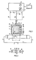
- FIG. 1 shows an electrically conductive component 1, which is connected to an alternating current source 2 by means of supply lines 3, 4, so that an alternating current IN can flow through it.
- the direction of current flow should be chosen for reasons of measurement accuracy in the direction of loading of the component.
- Material defects, e.g. B. small cracks 5 are present, which are to be determined, in particular their depth a is of interest.
- a measuring head 10 is placed on the structure 1 to be examined.
- the measuring probe has two electrically conductive pins 11, 12, which are provided with tips 13, 14 at their lower end. A certain voltage drops per unit of length on the current-carrying component 1, corresponding to the current strength.
- the measuring tips 13, 14 with the distance 1 tap this voltage over the area to be examined.
- This measuring device consists of suitable measuring electronics 6, preferably with a phase-selective one
- Amplifier a so-called lock-in amplifier.
- This amplifier selectively amplifies only the signals arriving at the measuring frequency and a specific phase at this measuring frequency.
- the voltage tapped off at the tips 13, 14 is fed to such a lock-in amplifier 6.
- the area between the two supply lines is made as small as possible.
- the one measuring pin 11 has at its lower end, as close as possible to the tip 13, a tap 15, from which an electrically insulated line 16a is guided as close as possible to the other pin 12 above the surface of the component 1.
- the line is then led upward around this pin 12 in a helical section 16b.
- the second feed line to the lock-in amplifier 6 begins at a tap 18 at the upper end of the measuring pin 12, from where a feed line 20 leads to the lock-in amplifier 6.
- Line 16b also continues there in a feed line 21 to lock-in amplifier 6.
- the lines 20, 21, if appropriate together with the line 19, should be strongly twisted in order to reduce influences from stray electromagnetic fields.
- the lines 20, 21 form the measuring input of the lock-in amplifier for measuring the voltage U R between the measuring tips 13, 14.
- the lock-in amplifier still requires information about phase f, with which the measuring voltage in relation to the AC voltage source 2 is to be selected.
- this information could be supplied to the lock-in amplifier 6 from the AC voltage source 2, but it has been shown that the current in the component 1 can be out of phase with the current source 2, in particular also depending on the routing of the leads 3, 4.
- the information about the phase position of the alternating current is therefore also directly at the measuring point won.
- the measuring head 10 has a conductor loop in its interior, which is formed from the measuring rod 11, the line section 16a, the helical line section 16b and the line 19.
- a voltage Ux is induced in this conductor loop in accordance with the change in the magnetic flux ⁇ , which voltage can be used as a reference signal for the phase information.
- the voltage Ux is fed to the lock-in amplifier with the aid of line 21 and line 19 starting at tap 17.
- the voltage U R to be measured must always be 90 ° out of phase with the voltage U x , which can be set accordingly on the lock-in amplifier 6 by means of a phase regulator 7.
- the computer can, if necessary, provide for an independent adjustment of the phase-P in the event of changed operating conditions.
- the voltage U x can also be measured with a corresponding phase shift to the voltage U R , as a result of which the local resistance at the measurement location can be determined.
- the measuring head itself should be constructed as a stable unit, whereby it can, for example, be cast in a block 22 made of a suitable material.
- This material should be temperature resistant, but also elastic against thermal expansion.
- a suitable material is, for example, water glass.
- FIG. 2 shows a schematic view from above of the measuring head for illustration.
- the pins 11, 12 with the feed lines and the conductor loop are cast in a block 22.
- the one from the head executing three lines 19, 20, 21 are preferably strongly twisted together.
- Such a measuring head can, as previously described, be used as a mobile probe, so that different locations of a structure can be examined in succession.
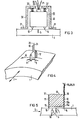
- a special holder for a measuring probe according to the invention which enables reproducible placement with a defined pressure on the structure.
- the probe 10 is arranged in a holding frame 30, 31, on which it is supported by means of compression springs or other elastic elements 32.
- the frame has feet 31 which can be pressed against the component 1. These feet 31 can, for example, also be equipped with magnets or with holding straps or the like for fastening to a structure.
- the holding frame 30, 31 should preferably consist of electrically non-conductive material in order not to influence the measurement.
- the component 1 is traversed by an alternating current I nI in the direction of the arrow. This leads to an alternating magnetic field perpendicular to the current direction. According to Maxwell's equations, the magnetic flux of a particular p ro- portional to be examined instead of the component to the current flowing at this point flow in the vicinity.
- the alternating magnetic field induces a voltage in a conductor loop, which is 90 ° out of phase.
- the alternating current flowing at a specific point in the structure can therefore be measured with the help of the alternating magnetic field generated by it.
- FIG. 5 shows the measuring head again in a schematic representation, the area of the conductor loop being hatched.
- This area which is delimited by the pin 11, the lines 16a, 16b and 19, determines the magnitude of the voltage U X.
- the area should be chosen so that U x and U R are of the same order of magnitude, so that errors on the lock-in amplifier do not occur due to the switching of the measuring range.
- the conductor loop could also consist of two or more turns with a smaller area. This would not change the measuring principle.
- the measuring lines 19, 20, 21 are led to the outside provided that they are only twisted together to eliminate interference. In general, the use of strongly twisted lines is recommended, in particular also for the supply lines from the alternating current source to component 1, insofar as this is possible.
- a certain increased resistance at a measuring point can, as indicated in FIG. 5, be due to a large crack 5 or to several small damages 50.
- one will generally determine an equivalent crack depth from the measured resistance in accordance with previous reference measurements, whereby the most unfavorable component state that could have this resistance is assumed by conservative assumptions.
- I mess is determined by a conductor loop near the measuring point, in which the change d ⁇ in the magnetic flux 0 generated by the current I mess induces a voltage U x .
- the level of the voltage U x still depends on the area and what is taken into account by a probe constant C probe of the number of turns if necessary, from the conductor loop, (the area of the conductor loop is not parallel to the line connecting the measuring points for U R and / or not perpendicular to the structure surface arranged, geometric factors must still be taken into account). It follows .
- C probe where C probe z. B. is determined by reference measurements. Since U x is out of phase with U R by 90 0 , this must be taken into account when forming the ratio. B. is possible in a lock-in amplifier with great accuracy.
- the value of determined in this way can be measured largely without interference and is well suited as an indication of the material condition.
- This value can be used to make a direct statement about the material condition and the depth of any cracks, if necessary compared to a reference measuring point.
- the probe according to the invention is also suitable for other measurements beyond the expressly described applications.
- the method also monitors the wall thickness of pipes, or material parameters such as temperature and the like can be determined. also on melts or liquids.
Landscapes
- Chemical & Material Sciences (AREA)
- Chemical Kinetics & Catalysis (AREA)
- Electrochemistry (AREA)
- Physics & Mathematics (AREA)
- Health & Medical Sciences (AREA)
- Life Sciences & Earth Sciences (AREA)
- Analytical Chemistry (AREA)
- Biochemistry (AREA)
- General Health & Medical Sciences (AREA)
- General Physics & Mathematics (AREA)
- Immunology (AREA)
- Pathology (AREA)
- Investigating Or Analyzing Materials By The Use Of Magnetic Means (AREA)
- Measurement Of Resistance Or Impedance (AREA)
Applications Claiming Priority (4)
| Application Number | Priority Date | Filing Date | Title |
|---|---|---|---|
| DE19843434801 DE3434801A1 (de) | 1984-09-21 | 1984-09-21 | Verfahren und vorrichtungen zur materialpruefung durch messung von elektrischer leistungsdichte-, stromdichte- oder spannungsverteilung an einem stromdurchflossenen bauteil |
| DE3434801 | 1984-09-21 | ||
| DE3501614 | 1985-01-18 | ||
| DE19853501614 DE3501614A1 (de) | 1985-01-18 | 1985-01-18 | Verfahren zur materialpruefung durch messen elektrischer groessen und vorrichtung sowie messkopf zur durchfuehrung des verfahrens |
Publications (1)
| Publication Number | Publication Date |
|---|---|
| EP0175257A2 true EP0175257A2 (fr) | 1986-03-26 |
Family
ID=25824969
Family Applications (1)
| Application Number | Title | Priority Date | Filing Date |
|---|---|---|---|
| EP85111387A Withdrawn EP0175257A2 (fr) | 1984-09-21 | 1985-09-09 | Méthode pour la surveillance d'une structure par la mesure de grandeurs électriques et appareil et tête de mesure pour l'application du procédé |
Country Status (2)
| Country | Link |
|---|---|
| US (1) | US4683419A (fr) |
| EP (1) | EP0175257A2 (fr) |
Cited By (3)
| Publication number | Priority date | Publication date | Assignee | Title |
|---|---|---|---|---|
| WO1988004028A1 (fr) * | 1986-11-25 | 1988-06-02 | Battelle Memorial Institute | Procede pour detecter des variations d'epaisseur dans la paroi d'un corps tubulaire conducteur de l'electricite |
| DE29608664U1 (de) * | 1996-05-13 | 1997-09-18 | Debnar Beinssen, Angelika, Dipl.-Ing., 20149 Hamburg | Vorrichtung zum Werkstoffprüfen einer metallischen Wand |
| GB2367631A (en) * | 2000-08-09 | 2002-04-10 | Rolls Royce Plc | Device and method for fatigue testing a specimen |
Families Citing this family (16)
| Publication number | Priority date | Publication date | Assignee | Title |
|---|---|---|---|---|
| US4764970A (en) * | 1985-04-15 | 1988-08-16 | Hitachi, Ltd. | Method and apparatus for detecting cracks |
| US4789829A (en) * | 1986-07-18 | 1988-12-06 | Science Application International Corporation | Method and apparatus for determining RE gasket shielding effectiveness |
| EP0289615B1 (fr) * | 1986-10-20 | 1996-02-07 | Hitachi, Ltd. | Procede et appareil de controle de defauts de surface |
| US4982158A (en) * | 1988-06-23 | 1991-01-01 | Electric Power Research Institute, Inc. | Method and apparatus for magnetic detection of flaws |
| GB8817725D0 (en) * | 1988-07-26 | 1988-09-01 | Matelect Ltd | Techniques to improve accuracy of measurement of crack depth by a c p d |
| GB2224575B (en) * | 1988-11-04 | 1993-07-14 | Technical Software Consultants | Electromagnetic microscope |
| GB2233763B (en) * | 1989-07-07 | 1994-06-15 | Univ Essex | Non-destructive testing of metals |
| DE69233065D1 (de) * | 1991-06-11 | 2003-06-26 | Newt Holdings Ltd | Sonde |
| US5612621A (en) * | 1992-10-27 | 1997-03-18 | Industrial Technology Research Institute | Method for monitoring cracks and critical concentration by using phase angle |
| WO1999005533A2 (fr) * | 1997-07-23 | 1999-02-04 | Pirelli Cavi E Sistemi S.P.A. | Systeme de mesure de la resistance serie equivalente en courant alternatif d'un conducteur |
| JP3553439B2 (ja) | 1999-11-16 | 2004-08-11 | 三菱重工業株式会社 | 亀裂モニタリング方法および亀裂モニタリング装置 |
| US6922641B2 (en) * | 2003-09-17 | 2005-07-26 | General Electric Company | System and method for monitoring defects in structures |
| JP2007327804A (ja) * | 2006-06-07 | 2007-12-20 | Nec Electronics Corp | 電圧降下測定回路 |
| EP2958844B1 (fr) * | 2013-02-21 | 2018-09-05 | Otis Elevator Company | Surveillance du bon état d'une corde d'ascenseur |
| US11016047B2 (en) * | 2017-08-25 | 2021-05-25 | 3M Innovative Properties Company | Temperature-corrected control data for verifying of structural integrity of materials |
| RU2680659C1 (ru) * | 2018-04-09 | 2019-02-25 | федеральное государственное бюджетное образовательное учреждение высшего образования "Ставропольский государственный аграрный университет" | Интегральный электрический способ неразрушающего контроля состояния винтовой цилиндрической пружины и устройство для его осуществления |
Family Cites Families (8)
| Publication number | Priority date | Publication date | Assignee | Title |
|---|---|---|---|---|
| US2351201A (en) * | 1942-07-16 | 1944-06-13 | Western Electric Co | Method of and means for measuring |
| BE630203A (fr) * | 1962-04-11 | |||
| GB1262749A (en) * | 1969-02-24 | 1972-02-02 | Nat Res Dev | Methods and apparatus for determining the condition of food |
| US3753089A (en) * | 1971-12-06 | 1973-08-14 | Ibm | Electronic switching transient detector and method for locating electrical power supply noise sources |
| DE2228277A1 (de) * | 1972-06-09 | 1973-12-20 | Gerhard Dr Ing Gille | Einrichtung zur kompensation von stoerspannungen bei elektrischen messgeraeten fuer die risstiefenmessung |
| US4048558A (en) * | 1975-08-06 | 1977-09-13 | Clark Goodman | Method and apparatus for detecting metal failures in situ |
| US4266185A (en) * | 1979-02-16 | 1981-05-05 | Dover & Partners Limited | Probes and apparatus for and methods of measuring crack depths |
| NO150136C (no) * | 1982-04-19 | 1985-02-08 | Sentralinst For Ind Forskning | Fremgangsmaate og anordning for overvaakning av store konstruksjoner av metall |
-
1985
- 1985-09-09 EP EP85111387A patent/EP0175257A2/fr not_active Withdrawn
- 1985-09-20 US US06/778,548 patent/US4683419A/en not_active Expired - Fee Related
Cited By (7)
| Publication number | Priority date | Publication date | Assignee | Title |
|---|---|---|---|---|
| WO1988004028A1 (fr) * | 1986-11-25 | 1988-06-02 | Battelle Memorial Institute | Procede pour detecter des variations d'epaisseur dans la paroi d'un corps tubulaire conducteur de l'electricite |
| CH670504A5 (fr) * | 1986-11-25 | 1989-06-15 | Battelle Memorial Institute | |
| US4947132A (en) * | 1986-11-25 | 1990-08-07 | Battelle Memorial Institute | Method for detecting thickness variations in the wall of a tubular body which conducts electricity |
| DE29608664U1 (de) * | 1996-05-13 | 1997-09-18 | Debnar Beinssen, Angelika, Dipl.-Ing., 20149 Hamburg | Vorrichtung zum Werkstoffprüfen einer metallischen Wand |
| GB2367631A (en) * | 2000-08-09 | 2002-04-10 | Rolls Royce Plc | Device and method for fatigue testing a specimen |
| US6732591B2 (en) | 2000-08-09 | 2004-05-11 | Rolls-Royce Plc | Device and method for fatigue testing of materials |
| GB2367631B (en) * | 2000-08-09 | 2004-12-22 | Rolls Royce Plc | A device and method for fatigue testing of materials |
Also Published As
| Publication number | Publication date |
|---|---|
| US4683419A (en) | 1987-07-28 |
Similar Documents
| Publication | Publication Date | Title |
|---|---|---|
| DE3813739C2 (fr) | ||
| DE3785185T2 (de) | Geraet und verfahren zum messen der stroemungscharakteristika einer petroleumstroemung. | |
| DE69230286T2 (de) | Apparat zur "in-line"-analyse von strömenden flüssigkeiten und festen materialien mittels magnetischer kernresonanz | |
| DE102009022136A1 (de) | Vorrichtung und Verfahren für induktive Messungen | |
| DE2007964B2 (de) | Verfahren und Gerät zur Bestimmung des Frischeverlustes einer Nahrungsmittelprobe | |
| DE102009022138A1 (de) | Vorrichtung und Verfahren für induktive Messungen | |
| DE69211532T2 (de) | Testsystem mit wechselfeldmessung | |
| EP0389916B1 (fr) | Appareil de mesure des propriétés diélectriques des matériaux | |
| DE3631571A1 (de) | Vorrichtung mit einem sensor zur messung des pruefstromes bei magnetelektrischen risspruefvorrichtungen | |
| DE1959406A1 (de) | Wirbelstrommessvorrichtung | |
| DE3401058A1 (de) | Verfahren zum zerstoerungsfreien identifizieren unterschiedlicher arten von konstruktions-walzstaehlen | |
| DE2641798B2 (de) | Verfahren und Einrichtung zum berührungslosen Ermitteln physikalischer oder geometrischer Eigenschaften | |
| DE3501614A1 (de) | Verfahren zur materialpruefung durch messen elektrischer groessen und vorrichtung sowie messkopf zur durchfuehrung des verfahrens | |
| DE2643914A1 (de) | Verfahren und einrichtung zum messen des spezifischen widerstandes von leitern und halbleitern | |
| DE2855511A1 (de) | Wirbelstrom-pruefvorrichtung | |
| DE4129259C2 (de) | Einrichtung zur Ermittlung der Materialbeschaffenheit elektrisch leitfähiger Körper | |
| DE3030069A1 (de) | Anordnung zur messung des elektrischen flaechenwiderstandes elektrisch leitender schichten | |
| DE2020749A1 (de) | Messvorrichtung fuer Querschnittsflaechen | |
| DE102021114407A1 (de) | Blasendetektionsvorrichtung und Verfahren zum Detektieren von Blasen in einer elektrisch leitfähigen Schmelze | |
| DE102005029414B4 (de) | Verfahren zur Bestimmung des durch Elektroporation bewirkenden Aufschlussgrades biologischer Zellen | |
| EP4180801B1 (fr) | Procédé de détermination d'au moins la teneur en fer métallique dans une éponge de fer ou dans un échantillon de celle-ci fabriqué par réduction directe | |
| DE941322C (de) | Messverfahren zur Dicken- bzw. Abstandsmessung unter Verwendung eines Kondensators, insbesondere eines Plattenkondensators mit beweglichen Platten | |
| DE1473863C3 (de) | Vorrichtung zum Ausmessen metallisch umkleideter Hohlräume | |
| EP1867422A2 (fr) | Dispositif et procédé destinés au traitement électromécanique de pièces à usiner | |
| DE102005040743B4 (de) | Verfahren und Anordnung zur zerstörungsfreien Prüfung |
Legal Events
| Date | Code | Title | Description |
|---|---|---|---|
| PUAI | Public reference made under article 153(3) epc to a published international application that has entered the european phase |
Free format text: ORIGINAL CODE: 0009012 |
|
| AK | Designated contracting states |
Kind code of ref document: A2 Designated state(s): AT BE CH DE FR GB IT LI LU NL SE |
|
| RAP1 | Party data changed (applicant data changed or rights of an application transferred) |
Owner name: INTERATOM GESELLSCHAFT MIT BESCHRAENKTER HAFTUNG |
|
| STAA | Information on the status of an ep patent application or granted ep patent |
Free format text: STATUS: THE APPLICATION IS DEEMED TO BE WITHDRAWN |
|
| 18D | Application deemed to be withdrawn |
Effective date: 19900403 |
|
| RIN1 | Information on inventor provided before grant (corrected) |
Inventor name: NEUELMANN, ROLF, DIPL.-ING. Inventor name: FORTMANN, MANFRED, DIPL.-ING. |