EP0175367A2 - Noise reduction circuit - Google Patents
Noise reduction circuit Download PDFInfo
- Publication number
- EP0175367A2 EP0175367A2 EP85111866A EP85111866A EP0175367A2 EP 0175367 A2 EP0175367 A2 EP 0175367A2 EP 85111866 A EP85111866 A EP 85111866A EP 85111866 A EP85111866 A EP 85111866A EP 0175367 A2 EP0175367 A2 EP 0175367A2
- Authority
- EP
- European Patent Office
- Prior art keywords
- circuit
- video signal
- output
- attenuation
- input video
- Prior art date
- Legal status (The legal status is an assumption and is not a legal conclusion. Google has not performed a legal analysis and makes no representation as to the accuracy of the status listed.)
- Withdrawn
Links
- 238000003708 edge detection Methods 0.000 claims abstract description 13
- 238000012935 Averaging Methods 0.000 claims abstract description 3
- 238000012545 processing Methods 0.000 description 14
- 238000010586 diagram Methods 0.000 description 5
- 239000002131 composite material Substances 0.000 description 3
- 230000006866 deterioration Effects 0.000 description 3
- 238000009499 grossing Methods 0.000 description 3
- 230000001934 delay Effects 0.000 description 1
- 230000003111 delayed effect Effects 0.000 description 1
- 238000000034 method Methods 0.000 description 1
Images



Classifications
-
- H—ELECTRICITY
- H04—ELECTRIC COMMUNICATION TECHNIQUE
- H04N—PICTORIAL COMMUNICATION, e.g. TELEVISION
- H04N5/00—Details of television systems
- H04N5/14—Picture signal circuitry for video frequency region
- H04N5/21—Circuitry for suppressing or minimising disturbance, e.g. moiré or halo
Definitions
- the present invention relates to a circuit for reducing the noise contained in a video signal.
- An object of the present invention is to provide a noise reduction circuit for reducing the noise contained in video signals with suppressing the deterioration of the resolution as small as possible.
- a noise reduction circuit which comprises a plurality of delay circuits for delaying an output video signal for different delay times respectively, an average circuit for averaging the outputs of the delay circuits, a subtraction circuit for subtracting the output of the average circuit from an input video signal, an attenuation circuit for attenuating the output of subtraction circuit, an addition circuit for adding the output of the attenuation circuit to the input video signal, and an edge detection circuit for detecting the existence of the edge of a pattern in the input video signal, the attenuation factor of the attenuation circuit being controlled by the output of the edge detection circuit.
- Fig. 1 is a block diagram of a noise reduction circuit according to one embodiment of the present invention.
- Fig. 2, Fig. 4 and Fig. 5 are schematic illustrations for showing the positional relations of video signals in the picture.
- Fig. 3 is a graph showing the characteristics of the improvement of the signal-to-noise ratio against the attenuation factor.
- Fig. 6 is a block diagram of a noise reduction circuit according to another embodiment of the present invention considering the time delay in the signal processing.
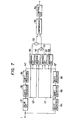
- Fig. 7 is a block diagram of an example of edge detection circuit.
- Fig. 8 is a schematic illustration for showing the positional relation of video signals which are used for detecting an edge of pattern.
- Fig. 9 is a graph showing a relation between an attenuation factor of attenuation circuit and an output of the edge detection circuit.
- Fig. 1 shows the block diagram of one embodiment of the present invention.
- reference numeral 1 denotes an input terminal of video signal
- 2 denotes a subtraction circuit
- 3 denotes an attenuation circuit
- 4 denotes an addition circuit
- 5 and 6 denote delay circuits respectively
- 7 denotes an average circuit
- 8 denotes an edge detection circuit
- 9 denotes an output terminal of the video signal.
- Fig. 2 shows the positional relation in the picture between the video signal 11 taken from the input terminal of the video signal 1 and the past video signal 12 for the time 2S past and the past video signal 13. for the time H-S past from the signal 11.
- H denotes one horizontal scanning period and S designates one half of the one period of the color subcarrier.
- H is 63.565 u sec. and S is 0.140 p sec. in the NTSC system.
- Reference numerals 21 and 22 denote horizontal scanning lines and the arrow heads of the horizontal scanning lines 21 and 22 illustrate the directions of scan.
- the past video signal 12 and 13 correspond to the outputs of the delay circuits 5 and 6 shown in Fig. 1 respectively.
- the signal processing is carried out using the above mentioned three video signal 11, 12 and 13 simultaneously.
- the average circuit 7 generates the averaged signal of the output video signals 12 and 13 delayed for the time 2S and H-S respectively by the delay circuits 5 and 6.
- the difference signal between said averaged signal and the input video signal 11 is generated by the subtraction circuit 2.
- Said difference signal is multiplied by k (0 ⁇ k ⁇ 1) in the attenuation circuit 3 according to whether the edge of the pattern picked up into the video signal is detected or not between the input video signal 11 and the 2S past output video signal 12, and between the input video signal 11 and the H-S past output video signal 13.
- the difference signal is added to the input video signal 11 in the addition circuit 4 and the result of addition is taken out as the noise reduced video signal from the video signal output terminal 9.
- the above mentioned output video signal is also given to delay circuits 5 and 6 and the same performance mentioned above is repeated.
- the above mentioned output video signal is at the same position. as the above mentioned input video signal 11.
- Equation (1) the principle of the noise reduction circuit of this embodiment will be explained.
- x(t) be the input video signal given to the video signal input terminal 1 at the time t and y(t) be the output video signal taken out from the video signal output terminal 9, then equation (1) is satisfied.
- y(t-2S) and y(t-H+S) mean the 2S and H-S past output video signals respectively.
- Z s and Z H be delay operators delaying for 2S and H-S respectively and by taking the Z transform of both sides of equation (1) therefore the transfer function may be described as Although there is a relation between Z H and Z s such that they may be considered to be almost independent mutually.
- equation (5) since the video signal is described as the summation of the amplitudes of the coefficients of Z S -j Z H j-i where Now since noise is described as the summation of the power (the squares) of the coefficients of Z S -j Z H j-i , from equation (5) where the following relations are used.
- equation (11) represents the improvement factor of the signal-to-noise ratio.
- Fig. 3 shows the improvement factor of the noise reduction circuit of this embodiment against the value of the attenuation factor k where the abscissa represents the value of k and the ordinate represents the improvement factor of the signal-to-noise ratio calculated by equation (11).
- the noise reduction circuit of this embodiment because the distance in the picture between the 2S past output video signal 12 and the input video signal 11 is nearly equal to the distance in the picture between the H-S past output video signal 13 and the input video signal 11, it may be considered that the strength of the correlation between the 2S past output video signal 12 and the input video signal 11 are also nearly equal to the strength of the correlation between the H-S past video signal 13 and the input video signal 12.
- Fig. 7 is a block diagram showing an example of the edge detection circuit 8.
- reference numeral 1 denotes an input terminal of video signal
- 81 denotes a delay circuit for delaying the video signal for 1H (one horizontal scanning period)
- 82, 83, 84, 85 and 86 denote shift registers each of which delays the video signal for 1S (a half of the one period of the color subcarrier) respectively
- .87, 88, 89 and 90 denote average circuits each of which produces the average value of two signals applied thereto respectively
- 91 and 92 denote subtraction circuits each of which produces the difference value between two inputted signals respectively
- 93 denotes a comparison circuit for comparing two signals applied thereto and delivering the larger one
- 94 denotes a control circuit for generating a control signal to control the attenuation factor k of the attenuation circuit 3 (shown in Fig. 1) in accordance with the output of the comparison circuit 93.
- Fig. 8 shows the positional relation of the video signals on the displayed picture, these video signals being used for detecting the edge of pattern.
- reference numerals 21 and 22 designate horizontal scanning lines. Arrow heads of lines 21 and 22 show the directions of scan.
- the video signals 12', 13' and 14' are the past input signals for the time 2S, H-S and H+S past from the input video signal 11'.
- the outputs of the subtraction circuits 91 and 92 are These outputs (91) and (92) represent respectively the variation of video signal in the horizontal and the vertical directions on the picture.
- u be the output of the comparison circuit 93, then u may be described as and the attenuation factor k may be described as a function of u
- u and k The functional relation between u and k is illustrated in Fig. 9.
- the output u of the comparison circuit 93 is large, that is to say, the edge of pattern is detected between the signals 11' and 12' or between the signals 11' and 13', and attenuation factor k of the attenuation circuit 3 becomes zero.
- the control circuit 94 In order to change the attenuation factor k in accordance with the function of u shown in Fig. 9, the control circuit 94 generates, in response to the output u of the comparison circuit 93, a control signal for controlling the attenuation circuit 3.
- edge detection circuit Since the edge detection circuit has to discriminate the edge of pattern, namely the variation of video signal from the noise in video signal and to pick up only the variation of video signal, it is necessary for the edge detection circuit not to be affected by the noise in video signal.
- Four average circuits 87, 88, 89 and 90 in the edge detection circuit of Fig. 7 are used for reducing the influence of noise by smoothing the signal and noise.
- video signals for processing when only luminance signal is processed, video signals for processing can be selected arbitrarily from the neighboring points in the picture, but when the composite signal itself is processed, signals for processing must be selected for the phases of all of the subcarriers for color signals to be same. Therefore, in the embodiment, for the input video signal it is devised not to cancel the color signal by using for signal processing the H-S past output video signal 13 and the 2S past output video signal 12 whose phases of all the subcarriers for color signals are same. At this time, for the input video signal 11, by using the H+S past output video signal 14 shown in Fig. 4 instead of using the H-S past output video signal 13, the composite signal itself can be processed.
- the use of the H-S past output video signal 13 leads to be harder to generate noise resulting in bad picture showing such as tailing lines and good results are obtained.
- the attenuation factor is controlled adaptively to the edge part and the other flat part, the improvement of the picture quality by more than 6 dB correspondence can be attained with preserving the resolution almost completely and moreover surely reducing noise.
- the total circuit can be constructed in small size and inexpensively.
Landscapes
- Engineering & Computer Science (AREA)
- Multimedia (AREA)
- Signal Processing (AREA)
- Picture Signal Circuits (AREA)
- Processing Of Color Television Signals (AREA)
Abstract
Description
- The present invention relates to a circuit for reducing the noise contained in a video signal.
- Up to this time, circuits for reducing noises by smoothing processings which utilize the property of strong line correlation of the video signals are known. However, as it is described in the official gazette of Japanese Patent Application Laid-open No. 211885/1982, if much more improvement in the signal-to-noise ratio is desired, then the pictures displayed on a monitor screen are grown indistinct remarkably and if the signals are processed utilizing only the line correlation, the components having line correlations among noises are emphasized and as a result, the noise generating disturbance in the vertical line in the displayed picture are remarkable. As a result, the improvements of the quality of the displayed picture can not be attained.
- An object of the present invention is to provide a noise reduction circuit for reducing the noise contained in video signals with suppressing the deterioration of the resolution as small as possible.
- The above object is accomplished according to the present invention by providing a noise reduction circuit which comprises a plurality of delay circuits for delaying an output video signal for different delay times respectively, an average circuit for averaging the outputs of the delay circuits, a subtraction circuit for subtracting the output of the average circuit from an input video signal, an attenuation circuit for attenuating the output of subtraction circuit, an addition circuit for adding the output of the attenuation circuit to the input video signal, and an edge detection circuit for detecting the existence of the edge of a pattern in the input video signal, the attenuation factor of the attenuation circuit being controlled by the output of the edge detection circuit.
- Fig. 1 is a block diagram of a noise reduction circuit according to one embodiment of the present invention. Fig. 2, Fig. 4 and Fig. 5 are schematic illustrations for showing the positional relations of video signals in the picture. Fig. 3 is a graph showing the characteristics of the improvement of the signal-to-noise ratio against the attenuation factor. Fig. 6 is a block diagram of a noise reduction circuit according to another embodiment of the present invention considering the time delay in the signal processing. Fig. 7 is a block diagram of an example of edge detection circuit. Fig. 8 is a schematic illustration for showing the positional relation of video signals which are used for detecting an edge of pattern. Fig. 9 is a graph showing a relation between an attenuation factor of attenuation circuit and an output of the edge detection circuit.
- A detailed description of the embodiments will be presented in the following by referring to the figures.
- Fig. 1 shows the block diagram of one embodiment of the present invention. In Fig. 1,
reference numeral 1 denotes an input terminal of video signal, 2 denotes a subtraction circuit, 3 denotes an attenuation circuit, 4 denotes an addition circuit, 5 and 6 denote delay circuits respectively, 7 denotes an average circuit, 8 denotes an edge detection circuit and 9 denotes an output terminal of the video signal. - Fig. 2 shows the positional relation in the picture between the
video signal 11 taken from the input terminal of thevideo signal 1 and thepast video signal 12 for thetime 2S past and thepast video signal 13. for the time H-S past from thesignal 11. H denotes one horizontal scanning period and S designates one half of the one period of the color subcarrier. H is 63.565 u sec. and S is 0.140 p sec. in the NTSC system.Reference numerals horizontal scanning lines past video signal delay circuits video signal - In the following, the performance of this embodiment is explained. The
average circuit 7 generates the averaged signal of theoutput video signals time 2S and H-S respectively by thedelay circuits input video signal 11 is generated by thesubtraction circuit 2. Said difference signal is multiplied by k (0≤ k< 1) in theattenuation circuit 3 according to whether the edge of the pattern picked up into the video signal is detected or not between theinput video signal 11 and the 2S pastoutput video signal 12, and between theinput video signal 11 and the H-S pastoutput video signal 13. After that the difference signal is added to theinput video signal 11 in theaddition circuit 4 and the result of addition is taken out as the noise reduced video signal from the videosignal output terminal 9. The above mentioned output video signal is also given to delaycircuits input video signal 11. - In the following, the principle of the noise reduction circuit of this embodiment will be explained. Let x(t) be the input video signal given to the video
signal input terminal 1 at the time t and y(t) be the output video signal taken out from the videosignal output terminal 9, then equation (1) is satisfied.


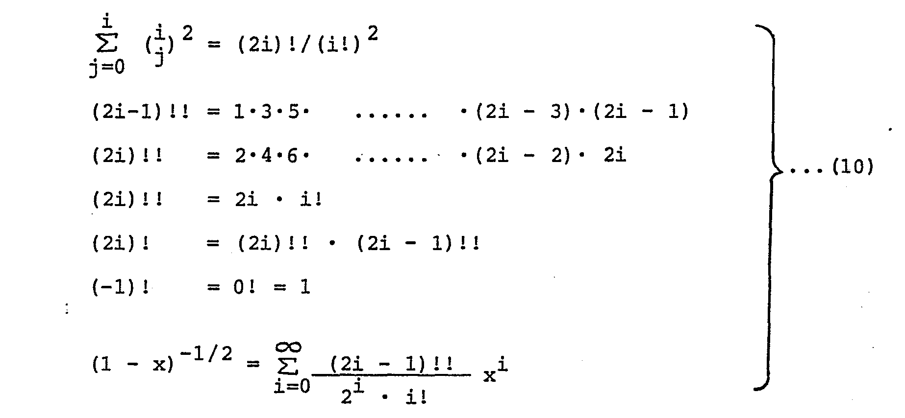
- Therefore, by extracting the square root of equation (9), the noise voltage is described, in dB unit, as

- Since the noise power is 1 and the noise voltage is 0 (dB) in the case that the present invention is not applied, equation (11) represents the improvement factor of the signal-to-noise ratio.
- For example, in the case of k=0.7, the improvement of the signal-to-noise ratio becomes to 9.0 dB. Fig. 3 shows the improvement factor of the noise reduction circuit of this embodiment against the value of the attenuation factor k where the abscissa represents the value of k and the ordinate represents the improvement factor of the signal-to-noise ratio calculated by equation (11).
- In the noise reduction circuit of this embodiment, as is shown in Fig. 2, because the distance in the picture between the 2S past
output video signal 12 and theinput video signal 11 is nearly equal to the distance in the picture between the H-S pastoutput video signal 13 and theinput video signal 11, it may be considered that the strength of the correlation between the 2S pastoutput video signal 12 and theinput video signal 11 are also nearly equal to the strength of the correlation between the H-Spast video signal 13 and theinput video signal 12. Saving conversely, because the simple mean is taken in theaverage circuit 7 by presupposing that the strength of the above mentioned correlations are nearly equal, the smoothing operation is not carried out by setting k=0 when the edge of pattern is detected in even either between the 2S pastoutput video signal 12 and theinput video signal 11 or between the H-S pastoutput video signal 13 and theinput video signal 11, and as a result, it leads to avoid the deterioration in the resula- tion. And for the case except the above, that is, when the edge is not detected in both between the above mentioned signals, enough reduction of noise is carried out by setting k large enough such as k=0.5 - 0.9. By means of the above, although large amount of noise is remained in the edge part comparing to the flat part, this noise does not make the viewer to worry because the characteristics of a viewer's vision is deteriorated for the edge part, hence this method is considered to be the way of noise reduction fitting to the characteristics of vision. - In the following, the
edge detection circuit 8 will be explained. Fig. 7 is a block diagram showing an example of theedge detection circuit 8. In Fig. 7,reference numeral 1 denotes an input terminal of video signal, 81 denotes a delay circuit for delaying the video signal for 1H (one horizontal scanning period), 82, 83, 84, 85 and 86 denote shift registers each of which delays the video signal for 1S (a half of the one period of the color subcarrier) respectively,.87, 88, 89 and 90 denote average circuits each of which produces the average value of two signals applied thereto respectively, 91 and 92 denote subtraction circuits each of which produces the difference value between two inputted signals respectively, 93 denotes a comparison circuit for comparing two signals applied thereto and delivering the larger one, and 94 denotes a control circuit for generating a control signal to control the attenuation factor k of the attenuation circuit 3 (shown in Fig. 1) in accordance with the output of thecomparison circuit 93. - Fig. 8 shows the positional relation of the video signals on the displayed picture, these video signals being used for detecting the edge of pattern. In Fig. 8,
reference numerals lines time 2S, H-S and H+S past from the input video signal 11'. - Let x(t) be the input video signal given to the
input terminal 1, then the outputs of theaverage circuit 


- Therefore, the outputs of the
subtraction circuits 

- Let u be the output of the
comparison circuit 93, then u may be described as

- The functional relation between u and k is illustrated in Fig. 9. When the output u of the
comparison circuit 93 is large, that is to say, the edge of pattern is detected between the signals 11' and 12' or between thesignals 11' and 13', and attenuation factor k of theattenuation circuit 3 becomes zero. In order to change the attenuation factor k in accordance with the function of u shown in Fig. 9, thecontrol circuit 94 generates, in response to the output u of thecomparison circuit 93, a control signal for controlling theattenuation circuit 3. - Since the edge detection circuit has to discriminate the edge of pattern, namely the variation of video signal from the noise in video signal and to pick up only the variation of video signal, it is necessary for the edge detection circuit not to be affected by the noise in video signal. Four
average circuits - In the present invention, when only luminance signal is processed, video signals for processing can be selected arbitrarily from the neighboring points in the picture, but when the composite signal itself is processed, signals for processing must be selected for the phases of all of the subcarriers for color signals to be same. Therefore, in the embodiment, for the input video signal it is devised not to cancel the color signal by using for signal processing the H-S past
output video signal 13 and the 2S pastoutput video signal 12 whose phases of all the subcarriers for color signals are same. At this time, for theinput video signal 11, by using the H+S pastoutput video signal 14 shown in Fig. 4 instead of using the H-S pastoutput video signal 13, the composite signal itself can be processed. However, as in this embodiment, the use of the H-S pastoutput video signal 13 leads to be harder to generate noise resulting in bad picture showing such as tailing lines and good results are obtained. This is due to the fact that the better results are obtained as the output video signals used for signal processing of theinput video signal 11 have stronger correlation to theinput video signal 11 but have weaker correlation between the output video signals used for signal processing of the input video signal (the correlation between thevideo signal video signal 12 and 14). Considering to this fact, it is better for the past output video signal used for the processing of theinput video signal 11 to be distant as far as possible in the picture and as is understood by comparing Fig. 2 to Fig. 4 better results are obtained in the case of selecting signals as in the embodiment. Alternatively, as is shown in Fig. 5, for theinput video signal 11, although it is possible to use the H-S and the H+S past output video signals 13 and 14 for the signal processing, due to the same reason as mentioned above, better results are obtained by the embodiment and hence it is the optimum to select signals as in this embodiment. - So far, the explanation is given by assumming that there is no delay during the signal processing. When there is any delay during the signal processing, the above explanation is also entirely valid by adding the
delay circuit 10 shown in Fig. 6 and compensating the delay time in the signal processing by thedelay circuits - By the embodiment, in principle enough noise reduction can be attained without the deterioration of the resolution and it is possible to reduce noise to about 15 dB down in the completely flat part of the signal such as the background in the picture by setting, for example, k=0.875.
- According to the present invention, since the attenuation factor is controlled adaptively to the edge part and the other flat part, the improvement of the picture quality by more than 6 dB correspondence can be attained with preserving the resolution almost completely and moreover surely reducing noise.
- Furthermore, because the signal processing is possible between signals whose phases of the subcarriers for color signnals are all same, and as a result the noise reduction is possible for the composite signal itself by no use of circuits such as a chroma inverter, the total circuit can be constructed in small size and inexpensively.
Claims (3)
Applications Claiming Priority (2)
| Application Number | Priority Date | Filing Date | Title |
|---|---|---|---|
| JP59196648A JPH0636602B2 (en) | 1984-09-21 | 1984-09-21 | Noise reduction circuit |
| JP196648/84 | 1984-09-21 |
Publications (2)
| Publication Number | Publication Date |
|---|---|
| EP0175367A2 true EP0175367A2 (en) | 1986-03-26 |
| EP0175367A3 EP0175367A3 (en) | 1987-03-18 |
Family
ID=16361267
Family Applications (1)
| Application Number | Title | Priority Date | Filing Date |
|---|---|---|---|
| EP85111866A Withdrawn EP0175367A3 (en) | 1984-09-21 | 1985-09-19 | Noise reduction circuit |
Country Status (4)
| Country | Link |
|---|---|
| US (1) | US4636863A (en) |
| EP (1) | EP0175367A3 (en) |
| JP (1) | JPH0636602B2 (en) |
| CA (1) | CA1228671A (en) |
Cited By (1)
| Publication number | Priority date | Publication date | Assignee | Title |
|---|---|---|---|---|
| DE3927101A1 (en) * | 1989-08-17 | 1991-02-21 | Nokia Unterhaltungselektronik | Video signal contained luminance signal processing - averages non-delayed and delayed luminance signals only when they differ by preset delay value |
Families Citing this family (15)
| Publication number | Priority date | Publication date | Assignee | Title |
|---|---|---|---|---|
| US4833634A (en) * | 1982-11-26 | 1989-05-23 | Coblitz David B | Multipurpose adaptive filter |
| US4825295A (en) * | 1985-08-09 | 1989-04-25 | Canon Kabushiki Kaisha | Image reading apparatus |
| KR900009063B1 (en) * | 1985-09-09 | 1990-12-17 | 니뽕 빅터 가부시끼가이샤 | Carrier color signal processing circuit |
| US4774569A (en) * | 1987-07-24 | 1988-09-27 | Eastman Kodak Company | Method for adaptively masking off a video window in an overscanned image |
| US4982294A (en) * | 1987-07-24 | 1991-01-01 | Eastman Kodak Company | Apparatus for enhancing and thresholding scanned microfilm images and methods for use therein |
| US4833722A (en) * | 1987-07-24 | 1989-05-23 | Eastman Kodak Company | Apparatus and methods for locating edges and document boundaries in video scan lines |
| US4853795A (en) * | 1987-07-24 | 1989-08-01 | Eastman Kodak Company | Forward look ahead techniques for tracking background and noise levels in scanned video images |
| US5144434A (en) * | 1989-07-13 | 1992-09-01 | Canon Kabushiki Kaisha | Video signal processing device using look-up table |
| JPH0370372A (en) * | 1989-08-10 | 1991-03-26 | Ikegami Tsushinki Co Ltd | noise suppression circuit |
| JPH0372778A (en) * | 1989-08-11 | 1991-03-27 | Fuji Xerox Co Ltd | Area identification system for picture processing unit |
| US5204920A (en) * | 1990-01-12 | 1993-04-20 | U.S. Philips Corporation | Method and apparatus for region and texture coding |
| US5325203A (en) * | 1992-04-16 | 1994-06-28 | Sony Corporation | Adaptively controlled noise reduction device for producing a continuous output |
| JP3306671B2 (en) * | 1992-09-24 | 2002-07-24 | 日本テキサス・インスツルメンツ株式会社 | Noise reduction circuit |
| KR0181286B1 (en) * | 1995-03-28 | 1999-05-01 | 김광호 | Defect Compensation Circuit of CCD Camera |
| JP3356201B2 (en) * | 1996-04-12 | 2002-12-16 | ソニー株式会社 | Video camera and contour enhancement device |
Family Cites Families (7)
| Publication number | Priority date | Publication date | Assignee | Title |
|---|---|---|---|---|
| GB1515551A (en) * | 1975-04-25 | 1978-06-28 | British Broadcasting Corp | Noise reduction in electrical signals |
| DE2962606D1 (en) * | 1978-04-03 | 1982-06-09 | British Broadcasting Corp | Noise reduction in electrical signals |
| JPS592227B2 (en) * | 1978-08-21 | 1984-01-17 | 株式会社日立製作所 | Noise removal method |
| JPS55179466U (en) * | 1979-06-11 | 1980-12-23 | ||
| JPS5827475A (en) * | 1981-08-11 | 1983-02-18 | Hitachi Ltd | Ghost eliminating device |
| DE3307687C3 (en) * | 1983-03-04 | 1994-04-28 | Broadcast Television Syst | System for reducing noise in a television signal |
| DE3477536D1 (en) * | 1983-11-28 | 1989-05-03 | Victor Company Of Japan | Noise reduction circuit for a video signal |
-
1984
- 1984-09-21 JP JP59196648A patent/JPH0636602B2/en not_active Expired - Lifetime
-
1985
- 1985-09-17 US US06/776,876 patent/US4636863A/en not_active Expired - Fee Related
- 1985-09-19 EP EP85111866A patent/EP0175367A3/en not_active Withdrawn
- 1985-09-23 CA CA000491347A patent/CA1228671A/en not_active Expired
Cited By (1)
| Publication number | Priority date | Publication date | Assignee | Title |
|---|---|---|---|---|
| DE3927101A1 (en) * | 1989-08-17 | 1991-02-21 | Nokia Unterhaltungselektronik | Video signal contained luminance signal processing - averages non-delayed and delayed luminance signals only when they differ by preset delay value |
Also Published As
| Publication number | Publication date |
|---|---|
| EP0175367A3 (en) | 1987-03-18 |
| CA1228671A (en) | 1987-10-27 |
| JPS6175674A (en) | 1986-04-18 |
| US4636863A (en) | 1987-01-13 |
| JPH0636602B2 (en) | 1994-05-11 |
Similar Documents
| Publication | Publication Date | Title |
|---|---|---|
| US4636863A (en) | Noise reduction circuit | |
| US4058836A (en) | Noise reduction in television signals | |
| US4524379A (en) | Double-scanning non-interlace television receiver with vertical aperture correction circuit | |
| US4241363A (en) | Comb filter circuit | |
| US4924305A (en) | Motion detecting circuit for video signal processing using correlation techniques | |
| EP0595663B1 (en) | Noise reduction for video signals | |
| US4860104A (en) | Noise eliminating apparatus of a video signal utilizing a recursive filter having spatial low pass and high pass filters | |
| US6693676B2 (en) | Motion detecting apparatus for detecting motion information of picture within signal | |
| US6611287B1 (en) | Camera signal processing apparatus and camera signal processing method | |
| EP0558017B1 (en) | Contour restoration apparatus | |
| EP0556501B1 (en) | Video motion detectors | |
| US4924315A (en) | Video signal processing system | |
| US5715000A (en) | Noise reduction circuit for reducing noise contained in video signal | |
| US5155582A (en) | Dot crawling interference elimination device and color subcarrier vertical correlation detection device | |
| US5635990A (en) | Apparatus for cancelling noise and improving details of images | |
| US5225898A (en) | Noise reduction apparatus for television receiver | |
| US5225899A (en) | Correlation adaptive luminance and chrominance signal separating circuit | |
| US5715015A (en) | Method of enhancing details contained in a color signal and a circuit for implementing the same in a color video apparatus | |
| EP0196756A2 (en) | Inter-dimensional chrominance noise reduction system | |
| US5218438A (en) | Picture aperture correction circuit | |
| US6259480B1 (en) | Sequential scanning converter | |
| US4882628A (en) | Amplitude characteristics of TV vertical frequency signal | |
| EP0194759A2 (en) | Wide bandwidth chrominance noise reduction system | |
| EP0660595B1 (en) | A noise reducer | |
| EP0426426B1 (en) | Filter device |
Legal Events
| Date | Code | Title | Description |
|---|---|---|---|
| PUAI | Public reference made under article 153(3) epc to a published international application that has entered the european phase |
Free format text: ORIGINAL CODE: 0009012 |
|
| 17P | Request for examination filed |
Effective date: 19850919 |
|
| AK | Designated contracting states |
Kind code of ref document: A2 Designated state(s): DE GB |
|
| PUAL | Search report despatched |
Free format text: ORIGINAL CODE: 0009013 |
|
| AK | Designated contracting states |
Kind code of ref document: A3 Designated state(s): DE GB |
|
| 17Q | First examination report despatched |
Effective date: 19890726 |
|
| STAA | Information on the status of an ep patent application or granted ep patent |
Free format text: STATUS: THE APPLICATION HAS BEEN WITHDRAWN |
|
| 18W | Application withdrawn |
Withdrawal date: 19891102 |
|
| RIN1 | Information on inventor provided before grant (corrected) |
Inventor name: KUBOTA, SADAO Inventor name: KAIZAKI, KAZUHIROFUJIMI-RYO Inventor name: HARADA, HIROSHI Inventor name: MATSUURA, SHIGEO |