EP0175372A1 - Messinstrument für Flüssigkeiten - Google Patents
Messinstrument für Flüssigkeiten Download PDFInfo
- Publication number
- EP0175372A1 EP0175372A1 EP85111883A EP85111883A EP0175372A1 EP 0175372 A1 EP0175372 A1 EP 0175372A1 EP 85111883 A EP85111883 A EP 85111883A EP 85111883 A EP85111883 A EP 85111883A EP 0175372 A1 EP0175372 A1 EP 0175372A1
- Authority
- EP
- European Patent Office
- Prior art keywords
- housing
- leadscrew
- fluid
- recited
- measurement gauge
- Prior art date
- Legal status (The legal status is an assumption and is not a legal conclusion. Google has not performed a legal analysis and makes no representation as to the accuracy of the status listed.)
- Ceased
Links
Images


Classifications
-
- G—PHYSICS
- G01—MEASURING; TESTING
- G01F—MEASURING VOLUME, VOLUME FLOW, MASS FLOW OR LIQUID LEVEL; METERING BY VOLUME
- G01F23/00—Indicating or measuring liquid level or level of fluent solid material, e.g. indicating in terms of volume or indicating by means of an alarm
- G01F23/30—Indicating or measuring liquid level or level of fluent solid material, e.g. indicating in terms of volume or indicating by means of an alarm by floats
- G01F23/48—Indicating or measuring liquid level or level of fluent solid material, e.g. indicating in terms of volume or indicating by means of an alarm by floats using twisted spindles as transmission elements
- G01F23/52—Indicating or measuring liquid level or level of fluent solid material, e.g. indicating in terms of volume or indicating by means of an alarm by floats using twisted spindles as transmission elements using electrically actuated indicating means
-
- G—PHYSICS
- G01—MEASURING; TESTING
- G01F—MEASURING VOLUME, VOLUME FLOW, MASS FLOW OR LIQUID LEVEL; METERING BY VOLUME
- G01F23/00—Indicating or measuring liquid level or level of fluent solid material, e.g. indicating in terms of volume or indicating by means of an alarm
- G01F23/30—Indicating or measuring liquid level or level of fluent solid material, e.g. indicating in terms of volume or indicating by means of an alarm by floats
- G01F23/48—Indicating or measuring liquid level or level of fluent solid material, e.g. indicating in terms of volume or indicating by means of an alarm by floats using twisted spindles as transmission elements
- G01F23/50—Indicating or measuring liquid level or level of fluent solid material, e.g. indicating in terms of volume or indicating by means of an alarm by floats using twisted spindles as transmission elements using mechanically actuated indicating means
Definitions
- the present invention pertains in general to apparatus for measuring fluid levels and in particular to such apparatus providing self- registration and high accuracy.
- the stocks of gasoline stored in service station tanks should be accurately and frequently measured to have control of the inventory as well as to detect theft and leakage losses.
- the most frequent way for measuring the stock of gasoline has been the use of a calibrated pole which is inserted into a gasoline tank by an operator to measure the depth of the gasoline in the tank. This depth reading is then converted to volume.
- this method leaves much to be desired.
- the accuracy of such measurements is not good. It is difficult to detect a loss of gasoline in a tank due to a slow leak since this could be masked by the actual withdrawal of fluid from the tank. There further needs to be unattended monitoring at frequent intervals to detect theft losses.
- a selected embodiment of the present invention is a fluid measurement gauge which includes a housing for extending into the body of the fluid.
- a leadscrew is positioned within the housing.
- a nut is engaged to the leadscrew for longitudinally traversing along the leadscrew in response to rotation of the leadscrew.
- a motor is provided for rotationally driving the leadscrew.
- a float is positioned exterior to the housing for floating at the surface of the fluid.
- a magnet is mounted on the float and a magnetic sensor is mounted to the nut, which is engaged to the leadscrew, for producing a detection signal when the sensor is in the vicinity of the magnet for thereby detecting the surface level of the fluid.
- the gauge 10 includes an elongate cylindrical housing 12 preferably fabricated of stainless steel.
- the housing 12 is, for example, two and one-half inches in diameter and from five to fifteen feet long. The dimensions, however, are dependent upon the application.
- the housing 12 is joined to a top plate 14.
- An adapter 16 has an upper flange portion thereof bonded to the top plate 14.
- the lower portion of the adapter 16 has external threads such that the adapter 16 can be threaded into a standard opening for a gasoline storage tank.
- a top bearing plate 18 is mounted to the top plate 14 by means of bolts 20 and 22.
- a top leadscrew bearing 28 is mounted in the top bearing plate 18 for weight-bearing and radial support of a leadscrew 30.
- a top printed circuit board 32 is mounted by means of screws 34 and 36 to the top bearing plate 18.
- An optical sensor 38 is mounted on the circuit board 32 and extends through the bearing plate 18 within the housing 12.
- the sensor 38 is, for example, a module H13Al-A13A2 manufactured by General Electric.
- the leadscrew 30 is supported on the top leadscrew bearing 28 which is mounted in the top bearing plate 18.
- a bottom leadscrew bearing 46 is mounted in a bottom bearing plate 48 which is in turn connected by a tension bracket 50 to the housing 12.
- Guide rods 52 and 54 are mounted within the housing 12 parallel to the leadscrew 30.
- Rod 52 extends through the plate 18 and the printed circuit board 32 and is secured in place by a nut 56.
- the guide rod 54 also extends through the plate 18 and the printed circuit board 32 where it is secured by a nut 58.
- the guide rod 52 is insulated from the bearing plate 18 by a shoulder insulator 60.
- the guide rod 54 is insulated from the bearing plate 18 by a shoulder insulator 62.
- the guide rod 52 passes through the bottom bearing plate 48, a shoulder insulator 64 where it is secured by a nut 66.
- the guide rod 54 extends through the plate 48 and a shoulder insulater 68, where it is secured by a nut 70.
- a mounting cover plate 80 is secured to the top plate 14 by bolts including 82.
- a cover 84 is mounted on the adapter plate 80 by screws which include 86, 88, 90 and 92.
- a conduit adapter 94 is mounted to the cover 84 to provide for the passage of electrical lines through the cover 84.
- a stepper motor 100 which is supported by motor standoffs 102, 104, 106 and 108.
- the standoffs are connected to the top bearing plate 18.
- the stepper motor 100 is, for example, a model MA61 manufactured by Superior Electric.
- the shaft of the motor 100 is connected by a sleeve coupling 110 to the leadscrew 30.
- a printed circuit board 112 is mounted on the top of the stepper motor 100 and is provided with various electronic control components.
- the gauge 10 is provided with external float guide rods 118 and 120.
- the rod 118 extends through a rod extension 122 and is secured to the plate 14 by nut 124.
- the guide rod 120 extends through the plate 14 and a guide rod extension 126 and is secured by nut 128.
- a bottom-flange plate 134 is connected to the tension bracket 50 and the housing 12.
- the guide rods 118 and 120 pass through the plate 134 and are secured respectively by nuts 136 and 138.
- a thermistor tube 140 is mounted parallel to the housing 12 and extends through a thermistor tube extension 142 within the plate 14 to open within the cover 84.
- the opening for the thermistor tube 140 is sealed by a thermistor tube O-ring 144.
- a plug 146 is secured at the bottom end of the thermistor tube 140 which is also provided with a nut 148.
- Within the tube 140 there are provided three thermistors 150, 152 and 154 for measuring the temperature of the fluid at different depths for temperature compensating the output of the gauge 10.
- a cylindrical float 160 encircles the housing 12 and is provided with a clearance notch 162 and holes 161 and 163 which guide rods 118 and 120 pass through to hold the float 160 at a predetermined rotational orientation with respect to the housing 12.
- the float 160 includes sleeves 160a and 160b which contact the rods118 and 120.
- the float 160 includes n a magnet 164.
- the float 160 is free to move up and down on the housing 12 to track the surface of the body of fluid which surrounds the housing 12.
- a second float 166 has a cylindrical shape and encircles the housing 12 in a similar manner to that of float 160.
- a magnet 168 is mounted within the float 166.
- a weight 170 is joined to the float 166 such that it is heavier than the float 160 and seeks the interface level between gasoline and water.
- the float 160 is designed to float at the surface of gasoline.
- a nut 176 is used in conjunction with the leadscrew 30.
- Nut 176 is longitudinally positioned on the leadscrew 30 in response to rotation of the leadscrew.
- the leadscrew 30 and the nut 176 comprise a high helix screw and flanged nut which are manufactured by Warner Electric Brake and Clutch Company.
- An optical interrupter 178 is mounted on the nut 176 and serves to interact with the optical sensor 38 to break a light path thereby indicating the position of the nu t 176.
- a printed circuit board 180- is mounted to the nut 176 by use of screws 182, 208 and 184 which extend through respective standoffs in which standoffs 190 and 192 are shown for screws 182 and 184.
- a plate 186 is also connected by the screws 182, 208 and 184 to the nut 176.
- a Hall-effect switch 188 is mounted on the printed circuit board 180 such that it is adjacent the interior of the housing 12 and can interact to detect the proximity of the magnets 164 and 168. The switch 188 is maintained in a constant orientation relative to the housing 12 such that it is aligned with the magnets 164 and 168. This alignment is maintained by the guide rods 52 and 54.
- Float 166 is provided with a clearance notch 172 and holes 173 and 174 which receive guide rods 118 and 120 to maintain a proper orientation about the housing 12.
- Sleeve bearings 204 and 206 are mounted to the nut 176 and receive the guide rods 52 and 54.
- the optical sensor 38 is connected through a line 194 to the printed circuit board 112.
- the thermistors 150, 152 and 154 are connected through a line 196 to the printed circuit board 112.
- the stepper motor 100 is driven by components on the printed circuit board 112 through a line 198.
- the guide rods 52 and 54 are connected respectively through lines 200 and.202 to the elements on the printed circuit board 112.
- FIGURE 3 there is shown a section view taken along lines 3-3 of the gauge illustrated in FIGURE 2.
- the top plate 14 top bearing plate 18, leadscrew 30, guide rods 52 and 54, and the cover 84.
- FIGURE 4 there is illustrated a section view taken along lines 4-4 of the gauge shown in FIGURE 2. This particularly shows the arrangement and components mounted on the nut 176.
- the printed circuit board 180 is secured to the nut 176 by screws 182 and 184 in addition to the screw 208.
- Brushes 210 and 212 are mounted on the printed circuit board 180 to contact the guide rod 52.
- the brushes 210 and 212 are electrically connected through a bracket 214 to a terminal screw 216.
- a line 218 connects the terminal screw 216 to the Hall-effect switch 188.
- Brushes 220 and 222 are mounted on the printed circuit board 180 to contact the guide rod 54.
- a bracket 224 electrically connects the brushes 220 and 222 to a terminal screw 226.
- a line 228 connects the terminal screw 226 to the Hall-effect device 188.
- gauge 10 is mounted in a fitting on a gasoline storage tank by means of the threads on the adapter 16.
- the housing 12 extends vertically downward into the fluid in the tank.
- a selected application is the measurement of the fluid level for a gasoline tank at a service station. Such tanks contain not only gasoline but water at the bottom of the tank.
- the float 160 settles at the top of the surface of the gasoline while the fluid 166 is weigthed to position itself at the interface between the gasoline and water.
- the control circuit on the printed circuit board 112 drives the stepper motor 100 to rotate the leadscrew 30 and cause the nut 176 to move upward until the optical interrupter 178 breaks the light beam in the optical sensor 38.
- the nut 176 is known to be at a reference position.
- the stepper motor 100 is then driven which causes the leadscrew 30 to rotate in a sequence of steps. The number of steps are counted as a measure of the distance of movement of the nut 176 from the reference position.
- the nut 176 descends until the switch 188 encounters the magnetic field of the magnet 164. The position of first detecting the magnetic field is noted and the nut 176 continues to move downward until the exit from the magnetic field is detected.
- the midpoint between the two detected points of the magnetic field is determined to be the position of the magnet 164 and therefore the level of the gasoline in the tank.
- Nut 176 is then driven by the stepper motor 100 downward until the Hall-effect switch 188 comes in proximity to the magnet 168 and again measures the entry and exit from the magnetic field of the magnet 168.
- the midpoint between these two position measurements is determined to be the interface level between the gasoline and the water.
- the position level determinations are made by the number of steps applied to the leadscrew 30 by operation of the stepper motor 100.
- the measured levels can then be transmitted to an external display (not shown) or to any other recording or indicator device as required by the particular application. In a typical application the measurement is made at a periodic interval and recorded to note the withdrawal of the gasoline and to note possible losses when no withdrawals are being made.
- a microprocessor controller 234 serves to generate the command for driving the stepper motor 100.
- Controller 234 is, for example, a model 8048 manufactured by Intel.
- the controller 234 further monitors the optical sensor 38 to determine when the nut 176 has reached the reference position.
- the temperature of the fluid in the tank is measured by the thermistors 150, 152 and 154. This temperature measurement is transmitted to the controller 234.
- the temperature of the fluid is used to correct the level measurements for changes in temperature.
- the guide rods 52 and 54 provide an electrical connection to the circuitry associated with the Hall-effect switch 188.
- the upper and lower indicated terminals of the switch 188 are connected respectively through the guide rods 52 and 54.
- Rod 52 is connected to ground.
- the switch 188 works in conjunction with a transistor 236.
- the middle terminal of the switch 188 is the switched terminal which is open in the absence of a magnetic field and connected to ground in the presence of a magnetic field. This middle terminal is connected to the base terminal of the transistor 236.
- the lower terminal of the Hall-effect switch 188 is connected to the collector terminal of transistor 236 and to ground through the rod 52.
- a resistor 237 is connected between the guide rod 54 and the emitter terminal or transistor 236.
- the guide rod 54 is electrically connected the noninverting input of a comparator 238.
- the negative input of comparator 238 is connected through a resistor 240 to ground.
- a resistor 242 is connected between a ten volt source and the noninverting input of comparator 238.
- a resistor 244 is connected between the ten volt source and the inverting input of comparator 238.
- the output of the comparator 238 is transmitted through a line 246 to the controller 234.
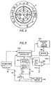
- the fluid-level measurements made by the gauge 10 can be transmitted by the microprocessor controller 234 to a receiver 250 display-printer for a local display of the measured fluid levels. From the receiver 250 the fluid level measurements can be provided to a modem 248 for transmission through telephone lines to a central office which monitors the fluid level in the gasoline tanks at a service station.
- the Hall-effect switch 188 works as follows. In the absence of a magnetic field, the base terminal of transistor 236 is at a high voltage, high impedence state. This turns off the transistor 236 which applies a high impedence to the rod 54. Under this condition the voltage at the noninverting input terminal of comparator 238 is at approximatley ten volts. But, the voltage divider action of resistors 244 and 240 produces a voltage of less than ten volts at the inverting input of comparator 238. The resulting output is a high voltage state which is transmitted to the controller 234 to indicate that there is not a magnet in the vicinity of the switch 188.
- the controller 234 For each measurement there must be a reference established for making the linear measurement of the surface level of the float.
- the controller 234 generates step commands for the motor 100 to draw the nut 176 upward until the optical interrupter 178 enters the optical sensor 38. When this occurs the reference position is establised for the nut 176 and associated switch 188.
- the controller 234, which is mounted on the printed circuit board 112 then drives the stepper motor 100 in an opposite direction to cause nut 176 to be driven downward.
- the comparator 238 produces a downgoing signal which is transmitted to the controller 234.
- the position of this occurrence is recorded by the controller 234 in its memory.
- the controller 234 then continues to drive the nut 176 downward until the switch 188 departs from the magnetic field of the magnet 164.
- the signal that is the output of the comparator 238 returns to a high voltage state thereby indicating to the controller 234 the position of departure from the magnetic field.
- the midpoint between these two measurements is then determined to be the level of the gasoline within the storage tank.
- the switch 188 In normal operation the switch 188 remains positioned adjacent to the magnet 164. When gasoline is withdrawn from the tank, the float 160 will be lowered and the switch 188 will change state thereby indicating through operation of the comparator 238 that the fluid level has changed. In a preferred method of operation, the controller 234 drives the stepper motor 100 to lower the nut 176 for determining the new fluid level. This hunting for new fluid levels occurs when gasoline is being withdrawn from the tank for sale.
- the level of water in the tank is carried out as' described above but the nut 176 is further driven to go below the float 160 and detect the magnet 168 carried by the float 166.
- the upper and lower edges of the magnetic field of the magnet 168 are determined and the midpoint is selected to be the interface level of the water and gasoline. This level is then reported in the same manner as above.
- a particularly significant feature of the gauge 10 is the periodic recalibration of the level measurement by movement to the predetermined reference position as indicated by the optical sensor 38. This eliminates any cumulative error buildup which can occur with systems which have only an initial calibration. Further, the use of the incremental stepper motor 100 provides a highly accurate measure of fluid level along the length of the leadscrew 30. A ten foot leadscrew 30 provies essentially the same accuracy as a five foot leadscrew 30. The use of the brushes 210, 212 and 220, 222 eliminates the need for any wiring between the switch 188 and the controller 234. The electrical measurement signals are transmitted through the fixed guide rods 52 and 54. The elimination of moving electrical conductors significantly reduces the failure possibilities of the gauge 10.
Landscapes
- Physics & Mathematics (AREA)
- Fluid Mechanics (AREA)
- General Physics & Mathematics (AREA)
- Level Indicators Using A Float (AREA)
Applications Claiming Priority (2)
| Application Number | Priority Date | Filing Date | Title |
|---|---|---|---|
| US653869 | 1984-09-21 | ||
| US06/653,869 US4554494A (en) | 1984-09-21 | 1984-09-21 | Fluid level gauge having magnetic sensor |
Publications (1)
| Publication Number | Publication Date |
|---|---|
| EP0175372A1 true EP0175372A1 (de) | 1986-03-26 |
Family
ID=24622602
Family Applications (1)
| Application Number | Title | Priority Date | Filing Date |
|---|---|---|---|
| EP85111883A Ceased EP0175372A1 (de) | 1984-09-21 | 1985-09-19 | Messinstrument für Flüssigkeiten |
Country Status (4)
| Country | Link |
|---|---|
| US (1) | US4554494A (de) |
| EP (1) | EP0175372A1 (de) |
| JP (1) | JPS61126428A (de) |
| CA (1) | CA1232467A (de) |
Families Citing this family (39)
| Publication number | Priority date | Publication date | Assignee | Title |
|---|---|---|---|---|
| US4744808A (en) * | 1986-10-30 | 1988-05-17 | Cobe Laboratories, Inc. | Liquid level sensing and control |
| GB2208330B (en) * | 1987-07-27 | 1991-12-04 | Hitachi Ltd | An optical disc cartridge and a mechanism for preventing an incorrect insertion of a cartridge. |
| US4804944A (en) * | 1987-09-01 | 1989-02-14 | Golladay James D | Hall effect liquid level sensing apparatus and method |
| US4944190A (en) * | 1988-09-19 | 1990-07-31 | Ametek Corporation | Flow meter |
| US5023806A (en) * | 1989-04-03 | 1991-06-11 | Patel Naresh P | Telecommunication system for remote LP gas inventory control |
| US5265032A (en) * | 1989-04-03 | 1993-11-23 | Patel Naresh P | Method for controlling LP gas inventory |
| US5136883A (en) * | 1990-08-24 | 1992-08-11 | Jannotta Louis J | Liquid level gage system |
| US5273134A (en) * | 1991-01-11 | 1993-12-28 | Dana Corporation | Oil consumption measurement system for internal combustion engine |
| US5479820A (en) * | 1993-10-12 | 1996-01-02 | Rochester Gauges, Inc. | Cryogenic gauge |
| US5812048A (en) * | 1993-11-24 | 1998-09-22 | Rochester Gauges, Inc. | Linear positioning indicator |
| US5907273A (en) * | 1993-11-24 | 1999-05-25 | Rochester Gauges, Inc. | Linear positioning indicator |
| US5501102A (en) * | 1993-11-24 | 1996-03-26 | Rochester Gauges, Inc. | Floatless gauge with resistive/conductive polymer |
| US5600998A (en) * | 1995-02-10 | 1997-02-11 | Dean, Jr.; William R. | Level sensor offset mounting mechanism |
| US5641006A (en) * | 1995-07-13 | 1997-06-24 | Chiron Diagnostics Corporation | Liquid supply apparatus and method of operation |
| US6336362B1 (en) | 1998-01-22 | 2002-01-08 | Roy A. Duenas | Method and system for measuring and remotely reporting the liquid level of tanks and the usage thereof |
| US6390590B1 (en) * | 1999-01-21 | 2002-05-21 | Oki Data Americas, Inc. | Apparatus for recording information about an ink cartridge |
| US6128967A (en) * | 1999-04-20 | 2000-10-10 | Seh America, Inc. | Level transmitter connector |
| US6711949B1 (en) * | 2001-02-01 | 2004-03-30 | Fluent Systems, Llc | Remote fluid level detection system |
| US20040079152A1 (en) * | 2001-02-01 | 2004-04-29 | Fluent Systems, Llc | Remote fluid level detection system |
| US6742396B2 (en) | 2001-04-07 | 2004-06-01 | Robertshaw Controls Company | Method for upgrading a dial indicator to provide remote indication capability |
| US6748805B2 (en) | 2002-01-17 | 2004-06-15 | Robert Shaw Controls Company | Multiple input level sensor |
| DE10321619A1 (de) * | 2003-05-13 | 2004-12-02 | Endress + Hauser Gmbh + Co. Kg | Verfahren zur Steuerung einer Logistikkette |
| US7082827B1 (en) * | 2003-06-19 | 2006-08-01 | Samuelson Scott R | Leak detector |
| US20040261525A1 (en) * | 2003-06-24 | 2004-12-30 | Jack Chen | Device for measuring the volume of fluid in a tank |
| US20050120793A1 (en) * | 2003-12-05 | 2005-06-09 | Cochran Edward R.Jr. | Tank fluid parameter monitoring device and method |
| US20060091295A1 (en) * | 2004-11-04 | 2006-05-04 | Staples Peter E | System to illuminate an enclosure |
| US8380355B2 (en) | 2007-03-19 | 2013-02-19 | Wayne/Scott Fetzer Company | Capacitive sensor and method and apparatus for controlling a pump using same |
| US20100001867A1 (en) * | 2007-12-28 | 2010-01-07 | Matthew Rodrigue | Device, system and method for monitoring tank content levels |
| US20110110794A1 (en) * | 2009-11-12 | 2011-05-12 | Philip Mayleben | Sensors and methods and apparatus relating to same |
| US20110110792A1 (en) * | 2009-11-12 | 2011-05-12 | Joseph Kendall Mauro | Sensors and methods and apparatus relating to same |
| CN103983327A (zh) * | 2014-06-03 | 2014-08-13 | 陈东 | 储油罐内三界面测量仪 |
| KR101756271B1 (ko) * | 2014-11-04 | 2017-07-11 | 한국지질자원연구원 | 자왜변위를 이용한 지하수 및 지표수의 수위 측정 센서 및 이를 이용한 지하수 및 지표수의 멀티 측정 시스템 |
| RU2594380C1 (ru) * | 2015-06-23 | 2016-08-20 | Общество с ограниченной ответственностью "Приборы автоцистерн" | Датчик уровня транспортного исполнения (варианты) и комплект оборудования для системы контроля параметров жидкости (варианты) |
| US10788355B2 (en) * | 2015-11-30 | 2020-09-29 | Bourns, Inc. | Detecting fluid level via a float |
| CN107764371A (zh) * | 2016-08-22 | 2018-03-06 | 荆门宏图延晟机械制造有限公司 | 带有机械与电子信号同步传感装置的侧装式液位计 |
| PL3529570T3 (pl) | 2016-10-21 | 2024-04-08 | Silicon Controls Pty Ltd | Urządzenie telemetryczne |
| US11162496B2 (en) | 2016-11-11 | 2021-11-02 | Wayne/Scott Fetzer Company | Pump with external electrical components and related methods |
| US10684157B2 (en) * | 2017-04-20 | 2020-06-16 | Rochester Gauges, Inc. | Liquid level gauge with integral electronic display |
| WO2025034473A1 (en) * | 2023-08-08 | 2025-02-13 | Fluid Handling Llc | Lead screw adjustable pump float switch for sump, effluent, and sewage applications |
Citations (5)
| Publication number | Priority date | Publication date | Assignee | Title |
|---|---|---|---|---|
| US1304022A (en) * | 1919-05-20 | Electrical indicating device | ||
| US3555905A (en) * | 1969-05-21 | 1971-01-19 | Clayton A George | Apparatus for measuring liquid in a tank |
| US3709038A (en) * | 1971-03-01 | 1973-01-09 | G Werner | Liquid level indicator |
| US4129039A (en) * | 1977-11-03 | 1978-12-12 | Gaetano Pignato | Dual gauge indicating device |
| DE3203110A1 (de) * | 1982-01-30 | 1983-08-18 | Sunvic Regler Gmbh, 5650 Solingen | Elektrischer messumformer fuer fuellstand |
Family Cites Families (4)
| Publication number | Priority date | Publication date | Assignee | Title |
|---|---|---|---|---|
| US3326042A (en) * | 1964-12-30 | 1967-06-20 | John D Ross | Ultrasonic liquid level indicator |
| US3969941A (en) * | 1973-11-08 | 1976-07-20 | E. Rapp Electronik Gmbh | Level detector for liquids and other flowable masses |
| JPS5821125A (ja) * | 1981-07-30 | 1983-02-07 | Toshiba Corp | 溶媒抽出槽の液々界面検出装置 |
| US4466284A (en) * | 1982-03-29 | 1984-08-21 | Sprague Electric Company | Fine resolution liquid level detector |
-
1984
- 1984-09-21 US US06/653,869 patent/US4554494A/en not_active Expired - Fee Related
-
1985
- 1985-09-19 EP EP85111883A patent/EP0175372A1/de not_active Ceased
- 1985-09-20 CA CA000491240A patent/CA1232467A/en not_active Expired
- 1985-09-21 JP JP60207809A patent/JPS61126428A/ja active Pending
Patent Citations (5)
| Publication number | Priority date | Publication date | Assignee | Title |
|---|---|---|---|---|
| US1304022A (en) * | 1919-05-20 | Electrical indicating device | ||
| US3555905A (en) * | 1969-05-21 | 1971-01-19 | Clayton A George | Apparatus for measuring liquid in a tank |
| US3709038A (en) * | 1971-03-01 | 1973-01-09 | G Werner | Liquid level indicator |
| US4129039A (en) * | 1977-11-03 | 1978-12-12 | Gaetano Pignato | Dual gauge indicating device |
| DE3203110A1 (de) * | 1982-01-30 | 1983-08-18 | Sunvic Regler Gmbh, 5650 Solingen | Elektrischer messumformer fuer fuellstand |
Also Published As
| Publication number | Publication date |
|---|---|
| CA1232467A (en) | 1988-02-09 |
| JPS61126428A (ja) | 1986-06-13 |
| US4554494A (en) | 1985-11-19 |
Similar Documents
| Publication | Publication Date | Title |
|---|---|---|
| US4554494A (en) | Fluid level gauge having magnetic sensor | |
| US5136884A (en) | Magnetic sight gage sensor | |
| US5146784A (en) | Sensor for measuring liquid-level changes in storage tanks | |
| US5243860A (en) | Liquid level measurement | |
| US3969941A (en) | Level detector for liquids and other flowable masses | |
| US6016697A (en) | Capacitive level sensor and control system | |
| US5253522A (en) | Apparatus for determining fluid level and fluid density | |
| US6928862B1 (en) | Method of monitoring dual-phase liquid and interface levels | |
| US9435679B2 (en) | Tethered float liquid level sensor | |
| US5136883A (en) | Liquid level gage system | |
| US7610807B2 (en) | Level gage | |
| US4442405A (en) | Float assembly for a sensor | |
| GB2132355A (en) | Measuring liquid level electrically | |
| WO1994007122A1 (en) | Density measurement | |
| NO156305B (no) | Anordning for registrering av nivaa, overgangssoner og temperatur. | |
| WO1994002820A1 (en) | Water sensor that detects tank or vessel leakage | |
| US6776028B1 (en) | Induction sensor viscometer | |
| US4007636A (en) | Liquid metal level indicator | |
| US5860316A (en) | Capacitance probe | |
| WO2000043735A2 (en) | Method and apparatus for measuring fluid levels in vessels | |
| US3487684A (en) | Precipitation measurement gauge | |
| US3459042A (en) | Float operated liquid level transmitter | |
| EP0570526B1 (de) | Gerät und verfahren zur detektion von öl auf wasser | |
| US6624755B1 (en) | Liquid level sensor apparatus and method | |
| SU620828A1 (ru) | Ультразвуковой индикатор уровн |
Legal Events
| Date | Code | Title | Description |
|---|---|---|---|
| PUAI | Public reference made under article 153(3) epc to a published international application that has entered the european phase |
Free format text: ORIGINAL CODE: 0009012 |
|
| AK | Designated contracting states |
Kind code of ref document: A1 Designated state(s): DE FR GB IT |
|
| 17P | Request for examination filed |
Effective date: 19860919 |
|
| 17Q | First examination report despatched |
Effective date: 19880316 |
|
| STAA | Information on the status of an ep patent application or granted ep patent |
Free format text: STATUS: THE APPLICATION HAS BEEN REFUSED |
|
| 18R | Application refused |
Effective date: 19880916 |
|
| RIN1 | Information on inventor provided before grant (corrected) |
Inventor name: HOWETH, JAMES R. |