EP0175502A2 - Tube à décharge pour une lampe à décharge à capteur métallique à haute pression et sa méthode de fabrication - Google Patents
Tube à décharge pour une lampe à décharge à capteur métallique à haute pression et sa méthode de fabrication Download PDFInfo
- Publication number
- EP0175502A2 EP0175502A2 EP85306012A EP85306012A EP0175502A2 EP 0175502 A2 EP0175502 A2 EP 0175502A2 EP 85306012 A EP85306012 A EP 85306012A EP 85306012 A EP85306012 A EP 85306012A EP 0175502 A2 EP0175502 A2 EP 0175502A2
- Authority
- EP
- European Patent Office
- Prior art keywords
- tubular body
- end plate
- discharge tube
- bonded
- high pressure
- Prior art date
- Legal status (The legal status is an assumption and is not a legal conclusion. Google has not performed a legal analysis and makes no representation as to the accuracy of the status listed.)
- Granted
Links
Images

Classifications
-
- H—ELECTRICITY
- H01—ELECTRIC ELEMENTS
- H01J—ELECTRIC DISCHARGE TUBES OR DISCHARGE LAMPS
- H01J61/00—Gas-discharge or vapour-discharge lamps
- H01J61/02—Details
- H01J61/36—Seals between parts of vessels; Seals for leading-in conductors; Leading-in conductors
- H01J61/361—Seals between parts of vessel
- H01J61/363—End-disc seals or plug seals
-
- H—ELECTRICITY
- H01—ELECTRIC ELEMENTS
- H01J—ELECTRIC DISCHARGE TUBES OR DISCHARGE LAMPS
- H01J9/00—Apparatus or processes specially adapted for the manufacture, installation, removal, maintenance of electric discharge tubes, discharge lamps, or parts thereof; Recovery of material from discharge tubes or lamps
- H01J9/24—Manufacture or joining of vessels, leading-in conductors or bases
- H01J9/26—Sealing together parts of vessels
- H01J9/265—Sealing together parts of vessels specially adapted for gas-discharge tubes or lamps
- H01J9/266—Sealing together parts of vessels specially adapted for gas-discharge tubes or lamps specially adapted for gas-discharge lamps
Definitions
- the present invention relates to a discharge tube for a high pressure metal vapour lamp, e.g. a metal halide discharge lamp, and a method for manufacturing the tube.
- a high pressure metal vapour lamp e.g. a metal halide discharge lamp
- a translucent alumina which withstands corrosive metal halides is used for a tubular body of a discharge tube of a high pressure metal vapour discharge lamp, particularly the metal halide lamp in which the metal halide is sealed, and alumina or cermet is used as end plates comprising electrode support members at the ends of the tubular body.
- a frit see, for instance, US Patent 3,885,184 and 4,001,625
- the present invention aims to reduce or avoid the above drawbacks of the prior art, and to provide a discharge tube for a high pressure metal vapour discharge lamp which can have a high discharge efficiency and a long durable life.
- a discharge tube for a high pressure metal vapour discharge lamp which discharge tube comprises a translucent alumina tubular body, a lower end plate bonded to one end portion of the alumina tubular body which has an electrode support member inside thereof and is bonded to the alumina tubular body when the alumina tube is subjected to the light transmission treatment through firing, another end plate which has an electrode support member inside thereof and is bonded to the other end of the translucent alumina tubular body by means of a frit.
- a method of manufacturing a discharge tube for a high pressure metal vapour discharge lamp comprises steps of inserting an end plate in which an electrode support member is partially embedded on the inner side thereof into one end portion of a tubular body made of high purity alumina, and firing the green or calcined tubular body with the end plate, whereby the tubular body is made translucent and simultaneously the end plate is bonded to the tubular body.
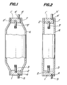
- the discharge tube for a high pressure metal vapour discharge lamp shown has an end plate l, and a recess 2 formed on the inner side of the end plate 1 into which an electrode support member 3 is fitted.
- the end plate 1 is bonded to a tubular body 6 at the lower end thereof while the tubular body 6 is rendered translucent by firing.
- An electric current conducting member 5 is fitted into a recess 4 formed in the end plate 1 at the outer side thereof.
- An end plate 1' of the same or similar shape as the end plate 1 carries an electrode support member 3' and an electric current conducting member 5'. This end plate is attached to the upper end portion of the discharge tubular body 6 by means of a frit 7.
- the end plate 1 is formed from a material of excellent electric conductivity such as alumina-tungsten, alumina-molybdenum tungsten boride. Then the electrode support member 3 made of tungsten is inserted into the recess 2 provided on the inner side of the end plate 1 and the electric current conductor 5 is inserted into the recess 4 on the outer side of the end plate 1. Thereafter, the electrode support member 3 and the electric current conductor 5 are bonded to the end plate 1 through firing. Before this, the green tubular body 6 is formed from high purity alumina, and is calcined in air.
- the above end plate 1 is fitted into one end of the calcined tubular body 6, and the whole tubular body with the end plate 1 is fired at a high temperature of around 1,900°C with hydrogen gas in a reducing atmosphere electric furnace to render the tubular body 6 translucent and at the same time firmly bond the end plate 1 to the tubular body 6. Since the firing shrinkage factor of the cermet constituting the end plate 1 is smaller than that of the high purity alumina constituting the tubular body 6, this bonding is carried out in the state of shrinkage fitting, while a gas tight bonding is achieved by sintering between the end plate and the high purity alumina.
- a metal halide is then put into the tubular body 6 to which the end plate is directly bonded at the lower end threof without use of frit.
- the sealed-in substance may change into liquid, so that the chemical reactivity at the inner surface of the lower end portion increases.
- the end plate 1' equipped with the electrode support member 3' and the electric current conductor 5', which end plate is preliminarily formed in the same way as mentioned above, is bonded to the upper end surface of the tubular body 6 by means of a glass frit 7.
- the profile of the tubular body 6 may be a cylindrical tubular form as shown in Fig. 2 instead of that shown in Fig. 1.
- the electric current conductors 5, 5' of the high pressure metal vapour discharge lamp thus produced are connected to an electric power source (not shown), electric current flows to the electrode support members 3 and 3' through the electric conductive end plates 1 and 1' to effect the discharge.
- the sealed-in substance is changed to liquid, but the bonded portion is not corroded by the liquid of high reactivity because the end plate 1 and the tubular body 6 are directly bonded through sintering without use of the frit at the lower end of the tubular body. Therefore, the discharge tube can be used at a temperature higher than the temperature of use of the conventional discharge tube of the metal halide discharge lamp, and a higher discharge efficiency can be obtained, while a long life can be attained.
- the electrode support members 3 and 3' may suitably pass through the end plates 1 and 1' to project outwardly.
- the other features of the embodiment shown in Fig. 3 are the same as or similar to those shown in Figs. 1 and 2. Detailed explanation of the embodiment of Fig. 3 is therefore omitted.
Landscapes
- Engineering & Computer Science (AREA)
- Manufacturing & Machinery (AREA)
- Vessels And Coating Films For Discharge Lamps (AREA)
- Manufacture Of Electron Tubes, Discharge Lamp Vessels, Lead-In Wires, And The Like (AREA)
Applications Claiming Priority (2)
| Application Number | Priority Date | Filing Date | Title |
|---|---|---|---|
| JP183294/84 | 1984-08-31 | ||
| JP59183294A JPS6161338A (ja) | 1984-08-31 | 1984-08-31 | 高圧金属蒸気放電灯用発光管の製造方法 |
Publications (3)
| Publication Number | Publication Date |
|---|---|
| EP0175502A2 true EP0175502A2 (fr) | 1986-03-26 |
| EP0175502A3 EP0175502A3 (en) | 1987-08-19 |
| EP0175502B1 EP0175502B1 (fr) | 1990-07-25 |
Family
ID=16133141
Family Applications (1)
| Application Number | Title | Priority Date | Filing Date |
|---|---|---|---|
| EP85306012A Expired - Lifetime EP0175502B1 (fr) | 1984-08-31 | 1985-08-23 | Tube à décharge pour une lampe à décharge à capteur métallique à haute pression et sa méthode de fabrication |
Country Status (7)
| Country | Link |
|---|---|
| US (2) | US4687969A (fr) |
| EP (1) | EP0175502B1 (fr) |
| JP (1) | JPS6161338A (fr) |
| AU (1) | AU559524B2 (fr) |
| CA (1) | CA1244870A (fr) |
| DE (1) | DE3578849D1 (fr) |
| HU (1) | HU192347B (fr) |
Cited By (4)
| Publication number | Priority date | Publication date | Assignee | Title |
|---|---|---|---|---|
| US5404078A (en) * | 1991-08-20 | 1995-04-04 | Patent-Treuhand-Gesellschaft Fur Elektrische Gluhlampen Mbh | High-pressure discharge lamp and method of manufacture |
| EP0722183A3 (fr) * | 1995-01-13 | 1996-10-30 | Ngk Insulators Ltd | Lampes à décharge haute tension |
| EP1006552A1 (fr) * | 1998-11-30 | 2000-06-07 | Osram Sylvania Inc. | Procédé de fabrication d'un tube d'arc en céramique pour lampes à halogénures métalliques |
| EP1363863A4 (fr) * | 2000-12-19 | 2007-08-15 | Gen Electric | Procede permettant d'obtenir des formes en ceramique complexes |
Families Citing this family (16)
| Publication number | Priority date | Publication date | Assignee | Title |
|---|---|---|---|---|
| JPS6161338A (ja) * | 1984-08-31 | 1986-03-29 | Ngk Insulators Ltd | 高圧金属蒸気放電灯用発光管の製造方法 |
| JPH0682545B2 (ja) * | 1986-12-24 | 1994-10-19 | 日本碍子株式会社 | 高圧金属蒸気放電灯用発光管 |
| JPH0719575B2 (ja) * | 1988-03-16 | 1995-03-06 | 日本碍子株式会社 | 高圧金属蒸気放電灯用発光管及びその製造方法 |
| US5188554A (en) * | 1988-05-13 | 1993-02-23 | Gte Products Corporation | Method for isolating arc lamp lead-in from frit seal |
| US5208509A (en) * | 1988-05-13 | 1993-05-04 | Gte Products Corporation | Arc tube for high pressure metal vapor discharge lamp |
| DE3840577A1 (de) * | 1988-12-01 | 1990-06-07 | Patent Treuhand Ges Fuer Elektrische Gluehlampen Mbh | Entladungsgefaess fuer eine hochdruckentladungslampe und verfahren zu dessen herstellung |
| US5057048A (en) * | 1989-10-23 | 1991-10-15 | Gte Laboratories Incorporated | Niobium-ceramic feedthrough assembly and ductility-preserving sealing process |
| EP0609477B1 (fr) * | 1993-02-05 | 1999-05-06 | Patent-Treuhand-Gesellschaft für elektrische Glühlampen mbH | Enceinte céramique à décharge pour lampe à décharge à haute pression et sa méthode de fabrication et matériau d'étanchéité associé |
| EP0879122B1 (fr) | 1995-06-02 | 2006-02-22 | A.h. Casting Services Limited | Procede de preparation d'une matiere ceramique a haute densite et grande resistance aux chocs thermiques |
| US6027389A (en) * | 1996-08-30 | 2000-02-22 | Ngk Insulators, Ltd. | Production of ceramic tubes for metal halide lamps |
| US5861714A (en) * | 1997-06-27 | 1999-01-19 | Osram Sylvania Inc. | Ceramic envelope device, lamp with such a device, and method of manufacture of such devices |
| US6020685A (en) * | 1997-06-27 | 2000-02-01 | Osram Sylvania Inc. | Lamp with radially graded cermet feedthrough assembly |
| EP1332514B1 (fr) * | 2000-11-06 | 2009-12-23 | Koninklijke Philips Electronics N.V. | Lampe a decharge haute pression |
| WO2007001387A2 (fr) * | 2004-10-01 | 2007-01-04 | Ceranova Corporation | Articles en alumine polycristalline et procedes de fabrication |
| JP5043123B2 (ja) | 2006-12-18 | 2012-10-10 | コーニンクレッカ フィリップス エレクトロニクス エヌ ヴィ | セラミック放電容器を有する高圧放電ランプ |
| DE102007055399A1 (de) | 2007-11-20 | 2009-05-28 | Osram Gesellschaft mit beschränkter Haftung | Hochdruckentladungslampe |
Family Cites Families (14)
| Publication number | Priority date | Publication date | Assignee | Title |
|---|---|---|---|---|
| DE1923138B2 (de) * | 1968-05-17 | 1973-07-19 | Corning, Glass Works, Corning, N Y V St A ) | Verfahren zur herstellung einer hermetischen verbindung wenigstens zweier polykristalliner koerper aus al tief 2 o tief 3 |
| BE795679A (fr) * | 1972-02-21 | 1973-08-20 | Philips Nv | Lampe a decharge a haute pression |
| BE798040A (fr) * | 1973-04-10 | 1973-07-31 | Piret Pierre | Procede pour la realisation de champs de formes quelconques pour les appareils de radiotherapie a haute energie et localisateur auxiliaire pour la mise en oeuvre du procede |
| NL7311290A (nl) * | 1973-08-16 | 1975-02-18 | Philips Nv | Werkwijze voor het afsluiten van een ontladings- |
| JPS52107177A (en) * | 1976-03-05 | 1977-09-08 | Hitachi Ltd | Producing method for discharge lamp of high vapor pressure |
| GB2029817A (en) * | 1978-09-06 | 1980-03-26 | Thorn Electrical Ind Ltd | Sealing of ceramic and cermet partds |
| AU528293B2 (en) * | 1980-02-06 | 1983-04-21 | Ngk Insulators, Ltd. | Discharge lamp tube |
| DE3166367D1 (en) * | 1980-12-20 | 1984-10-31 | Emi Plc Thorn | Method of producing a discharge lamp and discharge lamp produced thereby |
| NL8101177A (nl) * | 1981-03-11 | 1982-10-01 | Philips Nv | Samengesteld lichaam. |
| JPS5823158A (ja) * | 1981-08-04 | 1983-02-10 | Ngk Insulators Ltd | 金属蒸気放電灯用セラミツクチユ−ブの製造法 |
| DE3268402D1 (en) * | 1981-09-15 | 1986-02-20 | Emi Plc Thorn | Discharge lamps |
| DE3377249D1 (en) * | 1982-11-18 | 1988-08-04 | Emi Plc Thorn | Improvements in end closure members for discharge lamps |
| US4545799A (en) * | 1983-09-06 | 1985-10-08 | Gte Laboratories Incorporated | Method of making direct seal between niobium and ceramics |
| JPS6161338A (ja) * | 1984-08-31 | 1986-03-29 | Ngk Insulators Ltd | 高圧金属蒸気放電灯用発光管の製造方法 |
-
1984
- 1984-08-31 JP JP59183294A patent/JPS6161338A/ja active Granted
-
1985
- 1985-07-22 US US06/757,506 patent/US4687969A/en not_active Expired - Lifetime
- 1985-07-24 AU AU45311/85A patent/AU559524B2/en not_active Expired
- 1985-07-25 CA CA000487532A patent/CA1244870A/fr not_active Expired
- 1985-08-08 HU HU853071A patent/HU192347B/hu unknown
- 1985-08-23 DE DE8585306012T patent/DE3578849D1/de not_active Expired - Lifetime
- 1985-08-23 EP EP85306012A patent/EP0175502B1/fr not_active Expired - Lifetime
-
1987
- 1987-05-28 US US07/055,144 patent/US4800320A/en not_active Expired - Lifetime
Cited By (5)
| Publication number | Priority date | Publication date | Assignee | Title |
|---|---|---|---|---|
| US5404078A (en) * | 1991-08-20 | 1995-04-04 | Patent-Treuhand-Gesellschaft Fur Elektrische Gluhlampen Mbh | High-pressure discharge lamp and method of manufacture |
| EP0722183A3 (fr) * | 1995-01-13 | 1996-10-30 | Ngk Insulators Ltd | Lampes à décharge haute tension |
| US5783907A (en) * | 1995-01-13 | 1998-07-21 | Ngk Insulators, Ltd. | High pressure discharge lamps with sealing members |
| EP1006552A1 (fr) * | 1998-11-30 | 2000-06-07 | Osram Sylvania Inc. | Procédé de fabrication d'un tube d'arc en céramique pour lampes à halogénures métalliques |
| EP1363863A4 (fr) * | 2000-12-19 | 2007-08-15 | Gen Electric | Procede permettant d'obtenir des formes en ceramique complexes |
Also Published As
| Publication number | Publication date |
|---|---|
| DE3578849D1 (de) | 1990-08-30 |
| CA1244870A (fr) | 1988-11-15 |
| JPS6161338A (ja) | 1986-03-29 |
| EP0175502B1 (fr) | 1990-07-25 |
| HUT39287A (en) | 1986-08-28 |
| US4687969A (en) | 1987-08-18 |
| JPH0521298B2 (fr) | 1993-03-24 |
| AU559524B2 (en) | 1987-03-12 |
| EP0175502A3 (en) | 1987-08-19 |
| US4800320A (en) | 1989-01-24 |
| AU4531185A (en) | 1986-05-01 |
| HU192347B (en) | 1987-05-28 |
Similar Documents
| Publication | Publication Date | Title |
|---|---|---|
| EP0175502A2 (fr) | Tube à décharge pour une lampe à décharge à capteur métallique à haute pression et sa méthode de fabrication | |
| US5075587A (en) | High-pressure metal vapor discharge lamp, and method of its manufacture | |
| US20020145388A1 (en) | Seal for ceramic metal halide discharge lamp | |
| WO2010004472A2 (fr) | Lampe à décharge à vapeur de sodium haute pression avec antenne hybride | |
| EP0252448B1 (fr) | Source de lumière du type capsule pour lampe électrique | |
| US4804889A (en) | Electrode feedthrough assembly for arc discharge lamp | |
| US4625149A (en) | Metal vapor discharge lamp including an inner burner having tapered ends | |
| US7710039B2 (en) | Compact fluorescent lamp and method for manufacturing | |
| EP0011993A1 (fr) | Lampes à décharge électrique | |
| EP0121428A1 (fr) | Lampe fluorescente compacte avec guide métallique enrobé de verre pour l'arc | |
| CA1246655A (fr) | Capsule et mode d'alignement des electrodes pour lampes aux halogenures de faible puissance | |
| EP0204303A2 (fr) | Entrée de courant conique pour des températures élévées pour des lampes à décharge céramiques | |
| US6262533B1 (en) | Starting electrode for high pressure discharge lamp | |
| US5208509A (en) | Arc tube for high pressure metal vapor discharge lamp | |
| US5188554A (en) | Method for isolating arc lamp lead-in from frit seal | |
| US4147951A (en) | Gas discharge lamp having a double electrode arrangement | |
| US4659962A (en) | Low pressure discharge lamp | |
| EP0341749B1 (fr) | Enveloppe à arc pour lampe à décharge à vapeur métallique à haute pression, lampe avec une telle enveloppe et méthode de fabrication | |
| JPS63143738A (ja) | セラミツク放電灯 | |
| CA1155903A (fr) | Lampe a decharge de vapeur de metal basse pression | |
| US6359386B1 (en) | Electric lamp with metal shell | |
| HU182834B (en) | Electric current lead-in, preferably for discharge vessel of high-pressure gas-discharge light-sources | |
| EP0100091A2 (fr) | Scellement céramique pour lampes à vapeur de sodium à haute pression | |
| CN1008313B (zh) | 高压金属蒸汽放电灯的放电管及其制造方法 | |
| EP0596676B1 (fr) | Lampe à décharge dans le sodium à haute pression |
Legal Events
| Date | Code | Title | Description |
|---|---|---|---|
| PUAI | Public reference made under article 153(3) epc to a published international application that has entered the european phase |
Free format text: ORIGINAL CODE: 0009012 |
|
| 17P | Request for examination filed |
Effective date: 19851008 |
|
| AK | Designated contracting states |
Kind code of ref document: A2 Designated state(s): DE FR GB NL |
|
| PUAL | Search report despatched |
Free format text: ORIGINAL CODE: 0009013 |
|
| AK | Designated contracting states |
Kind code of ref document: A3 Designated state(s): DE FR GB NL |
|
| 17Q | First examination report despatched |
Effective date: 19880803 |
|
| GRAA | (expected) grant |
Free format text: ORIGINAL CODE: 0009210 |
|
| AK | Designated contracting states |
Kind code of ref document: B1 Designated state(s): DE FR GB NL |
|
| REF | Corresponds to: |
Ref document number: 3578849 Country of ref document: DE Date of ref document: 19900830 |
|
| ET | Fr: translation filed | ||
| PLBE | No opposition filed within time limit |
Free format text: ORIGINAL CODE: 0009261 |
|
| STAA | Information on the status of an ep patent application or granted ep patent |
Free format text: STATUS: NO OPPOSITION FILED WITHIN TIME LIMIT |
|
| 26N | No opposition filed | ||
| REG | Reference to a national code |
Ref country code: GB Ref legal event code: IF02 |
|
| PGFP | Annual fee paid to national office [announced via postgrant information from national office to epo] |
Ref country code: GB Payment date: 20040813 Year of fee payment: 20 |
|
| PGFP | Annual fee paid to national office [announced via postgrant information from national office to epo] |
Ref country code: FR Payment date: 20040823 Year of fee payment: 20 |
|
| PGFP | Annual fee paid to national office [announced via postgrant information from national office to epo] |
Ref country code: DE Payment date: 20040827 Year of fee payment: 20 |
|
| PGFP | Annual fee paid to national office [announced via postgrant information from national office to epo] |
Ref country code: NL Payment date: 20040831 Year of fee payment: 20 |
|
| PG25 | Lapsed in a contracting state [announced via postgrant information from national office to epo] |
Ref country code: GB Free format text: LAPSE BECAUSE OF EXPIRATION OF PROTECTION Effective date: 20050822 |
|
| PG25 | Lapsed in a contracting state [announced via postgrant information from national office to epo] |
Ref country code: NL Free format text: LAPSE BECAUSE OF EXPIRATION OF PROTECTION Effective date: 20050823 |
|
| REG | Reference to a national code |
Ref country code: GB Ref legal event code: PE20 |
|
| NLV7 | Nl: ceased due to reaching the maximum lifetime of a patent |
Effective date: 20050823 |