EP0175529B1 - Récipient exempt de dispositif de perforation - Google Patents
Récipient exempt de dispositif de perforation Download PDFInfo
- Publication number
- EP0175529B1 EP0175529B1 EP85306369A EP85306369A EP0175529B1 EP 0175529 B1 EP0175529 B1 EP 0175529B1 EP 85306369 A EP85306369 A EP 85306369A EP 85306369 A EP85306369 A EP 85306369A EP 0175529 B1 EP0175529 B1 EP 0175529B1
- Authority
- EP
- European Patent Office
- Prior art keywords
- container
- bore
- wall
- insert member
- flexible
- Prior art date
- Legal status (The legal status is an assumption and is not a legal conclusion. Google has not performed a legal analysis and makes no representation as to the accuracy of the status listed.)
- Expired
Links
- 239000000463 material Substances 0.000 claims description 17
- 238000004891 communication Methods 0.000 claims description 5
- 230000035515 penetration Effects 0.000 claims description 3
- 229920002457 flexible plastic Polymers 0.000 abstract description 4
- 238000011109 contamination Methods 0.000 abstract 1
- 238000007789 sealing Methods 0.000 description 11
- 239000004033 plastic Substances 0.000 description 10
- 229920003023 plastic Polymers 0.000 description 10
- 238000004519 manufacturing process Methods 0.000 description 8
- 230000002093 peripheral effect Effects 0.000 description 6
- 239000002985 plastic film Substances 0.000 description 5
- 239000000243 solution Substances 0.000 description 5
- 239000004743 Polypropylene Substances 0.000 description 3
- 239000011888 foil Substances 0.000 description 3
- 239000007788 liquid Substances 0.000 description 3
- 238000000034 method Methods 0.000 description 3
- -1 polypropylene Polymers 0.000 description 3
- 229920001155 polypropylene Polymers 0.000 description 3
- 229920001169 thermoplastic Polymers 0.000 description 3
- 239000004416 thermosoftening plastic Substances 0.000 description 3
- 239000008280 blood Substances 0.000 description 2
- 210000004369 blood Anatomy 0.000 description 2
- 239000000385 dialysis solution Substances 0.000 description 2
- 238000001990 intravenous administration Methods 0.000 description 2
- 239000002991 molded plastic Substances 0.000 description 2
- 230000000149 penetrating effect Effects 0.000 description 2
- 239000012858 resilient material Substances 0.000 description 2
- 239000008174 sterile solution Substances 0.000 description 2
- 238000005406 washing Methods 0.000 description 2
- LFQSCWFLJHTTHZ-UHFFFAOYSA-N Ethanol Chemical compound CCO LFQSCWFLJHTTHZ-UHFFFAOYSA-N 0.000 description 1
- VGGSQFUCUMXWEO-UHFFFAOYSA-N Ethene Chemical group C=C VGGSQFUCUMXWEO-UHFFFAOYSA-N 0.000 description 1
- 239000005977 Ethylene Substances 0.000 description 1
- 230000015572 biosynthetic process Effects 0.000 description 1
- 229920001577 copolymer Polymers 0.000 description 1
- 230000001419 dependent effect Effects 0.000 description 1
- 238000000502 dialysis Methods 0.000 description 1
- 238000009472 formulation Methods 0.000 description 1
- 238000007567 mass-production technique Methods 0.000 description 1
- 239000000203 mixture Substances 0.000 description 1
- 229920000098 polyolefin Polymers 0.000 description 1
- 229920005606 polypropylene copolymer Polymers 0.000 description 1
- 239000004800 polyvinyl chloride Substances 0.000 description 1
- 229920000915 polyvinyl chloride Polymers 0.000 description 1
- 230000005855 radiation Effects 0.000 description 1
- 230000000717 retained effect Effects 0.000 description 1
- 239000007787 solid Substances 0.000 description 1
- 230000001954 sterilising effect Effects 0.000 description 1
- 238000004659 sterilization and disinfection Methods 0.000 description 1
- 239000000126 substance Substances 0.000 description 1
- 239000000725 suspension Substances 0.000 description 1
- 238000003856 thermoforming Methods 0.000 description 1
Images


Classifications
-
- A—HUMAN NECESSITIES
- A61—MEDICAL OR VETERINARY SCIENCE; HYGIENE
- A61J—CONTAINERS SPECIALLY ADAPTED FOR MEDICAL OR PHARMACEUTICAL PURPOSES; DEVICES OR METHODS SPECIALLY ADAPTED FOR BRINGING PHARMACEUTICAL PRODUCTS INTO PARTICULAR PHYSICAL OR ADMINISTERING FORMS; DEVICES FOR ADMINISTERING FOOD OR MEDICINES ORALLY; BABY COMFORTERS; DEVICES FOR RECEIVING SPITTLE
- A61J1/00—Containers specially adapted for medical or pharmaceutical purposes
- A61J1/05—Containers specially adapted for medical or pharmaceutical purposes for collecting, storing or administering blood, plasma or medical fluids ; Infusion or perfusion containers
- A61J1/10—Bag-type containers
Definitions
- This application relates to an improved container having flexible plastic walls, for sterile solutions or the like.
- Flexible plastic solution containers are used in great quantities in the medical field for holding sterile solution for intravenous use, blood, sterile washing solutions, peritoneal dialysis solutions and the like.
- Typical designs of flexible containers include the Viaflex ® containers for intravenous solutions and the Dianeal® peritoneal dialysis solution containers sold by Travenol Laboratories, Inc.
- Conventional flexible plastic containers carry tubular ports at one end which are proportioned to receive a spike connector of an administration set.
- the spike connector passes into a tubular port passing through a diaphragm into flow communication with the solution contents of the container.
- US-A 3030952 discloses a container in which an insert is provided having a bore.
- the puncture member may be inserted through the flexible wall of the container into the bore so that the member is sealingly held in the bore.
- the insert is freely floating within the container.
- GB-A 1 104359 also discloses such an insert within a container, but the insert is heat-sealed to a side wall of the container.
- CH-A 3 999 297 discloses such an insert which is held in place within a container by means of a band clamping a portion of the container wall about the insert.
- the pre-characterising clause of Claim 1 is based on the disclosure of GB-A 1 104359.
- the present invention provides a container having opposed flexible walls sealed to each other at their edges and having a puncturable portion, an insert member positioned within the container and having a bore for sealingly receiving a puncture member after penetration of the latter through the puncturable portion so as to provide flow communication between the interior of the container and the puncture member, the insert member being held in a position with an end of the bore adjacent the puncturable portion, characterised in that said puncturable portion extends laterally of said flexible walls at one end of the container and the bore of the insert member is offset from the plane containing said edges and extends generally parallel to said plane.
- the puncture member As the puncture member passes into the bore, it typically causes an annular portion of the container wall to deform or stretch into a position between the puncture member and the aperture wall, where the annular portion can be sealingly locked and seated between the connected puncture member and bore wall. Thus, leakage can be prevented.
- the container wall may define a flexible-walled protrusion communicating with the rest of the container through a relatively narrow neck portion, to permit flow communication between the protrusion and the rest of the container.
- the insert member is advantageously captured or retained in the protrusion, to provide it with a fixed location without the need to seal it to the inner wall of the container.
- the container may also carry removable tape means on the outer surface of the flexible wall.
- the tape means may be applied to the container prior to sterilization, so that the tape means may be removed, when use of the container is desired, to expose a clean, typically sterile surface for puncturing by the puncture member. Thus, no alcohol swab or the like may be required prior to the use of the device of this invention.
- the container of this invention may be made from a pair of plastic sheets, or a large, extruded, flattened tubular plastic sheet, by appropriate peripheral heat sealing in a manner analogous to present commercial container manufacture techniques.
- a plastic sheet may be folded over and then peripherally sealed together on all open sides to form the container.
- the insert member may in this circumstance be simply placed between facing plastic sheets within the newly-formed container before the peripheral sealing operation, to provide a very efficient, cost effective manufacturing technique, since no separate application of port tubes is required.
- thermoplastic or other resilient materials may be used to make the container wall
- one preferred material is DYPRO O Z4650 polypropylene copolymer, sold by the Arco Chemical Company.
- the plastic material used may, if desired, be about 0.25 mm (0.01 inch) thick and may optionally be a coextrusion of the above recited DYPRO plastic material as an inner layer, and polypropylene as an outer layer of the container wall.
- the insert member in turn, may be made from a polypropylene material, for example having about 3 weight percent of copolymerized ethylene units in the formulation.
- the insert member may comprise a pair of tubes in telescoping relation with each other and connected at one end, with the bore as defined above being defined by the bore of the inner tube. This structure provides a certain desirable resilience to the insert member, and facilitates the seal formed between a puncture member and the aperture wall.
- the insert member In the specific instance of DYPRO" Z4650 copolymer, it is be desirable for the insert member to be made of a generally rigid material such as polypropylene as mentioned above. However, in other instances, for use with other resilient sheet materials, it may be disirable to use a softer, semi- flexible insert member.
- the aperture of the insert member may be proportioned to be of a diameter which is dependent upon the wall thickness of the facing plastic sheets, so that on penetration of the container wall by a puncture member, the annular portion of the container wall is formed by deformation and stretching into the desired sealing position between the puncture member and the bore wall.
- the various dimensions and proportions of the system may vary in accordance with frictional characteristics of the puncture member and insert member with the plastic of the container wall to optimize the formation of the desired deformed or stretched annular portion used for sealing between the connected puncture member and bore wall. Additionally, one may adjust the sharpness of the puncture member to provide the desired results. For example, it may be desired to provide a sharp spike with a highly resilient material, coupled with materials that provide a rather high coefficient of friction. On the other hand, when using a bag wall material that is not very resilient, a duller spike may be desired in some instances, and one may wish to use materials that have a realtively lower coefficient of friction. On the other hand, a sharp spike may be used in this instance as well for facilitating access to the container.
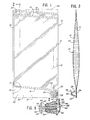
- Figure 1 is a plan view of a flexible, collapsible container (not in accordance with the invention) with a portion broker away.
- bag 10 is made of a pair of overlying thermoplastic sheets 12, 14, which are heat sealed together.
- a peripheral heat seal 16 is used.
- the seal may be made by conventional radio frequency sealing processes if polyvinylchloride sheeting is used, or by a hot bar seal if polyolefin sheeting or the like is used.
- the top of container 10 may carry other peripheral seals 18, and a corner hanger hole 20 for suspension of the container.
- flexible-walled protrusion 22 is defined, being surrounded by the extension 24 of heat seal 16.
- sheet 12 defines a portion of protrusion 22 which may be thermoformed in conventional manner to form a pocket 26.
- Pocket 26 receives and holds insert member 28, which may be a molded plastic piece of a design shown in longitudinal section in Figure 3.
- tape member 30 may be provided, adhering to an outer end of pocket 26 as shown in Figure 2.
- Tape member 30 may be a known plastic foil tab which is sealed to bag 10, defining a handle portion 32, so it can be manually removed to expose the surface of pocket 26 underneath foil tab 30. If foil tab 30 is applied and then bag 10 is radiation or steam sterilized, for example, removal of tab 30 can present a sterile surface to the user for application of a spike connector 34 to bag 10 to obtain access thereto.
- insert member 28 may be a single, molded plastic piece comprising a pair of tubular portions 36, 38, joined together at one end 40 in telescoping relation.
- the outertelescop- ing portion 36 serves as a good manual gripping member, so that one may hold protrusion 22 with the fingers, thus also gripping insert member 28.
- One may then manually advance spike 34, penetrating the wall of protrusion 22 to gain access to container 10.
- Portions of the container wall 42 may be stretched to fold inwardly into bore 44 of insert member 28 as spike 34 penetrates bore 44, so that wall portions 42 provide an added sealing lip or ring to the connection system between spike 34 and insert member 28. Accordingly, liquid 46 in container 10 may pass through the lumen of spike 34 into an administration set or the like, for flow communication between the bag interior and the set to which spike 34 is attached.
- the telescoping tube structure of insert member 28 provides a certain resilience to the tube 38 defining bore 44 which can improve the sealing characteristics of the insert member with spike 34. Also, less plastic is used, when compared with a solid piece insert member which does not define annular space 48.
- FIG. 3 The illustration of Figure 3 is somewhat schematic.
- the inner wall of tube 38 defining bore 44 will be commonly expected to contact the outer wall of spike 34, to provide improved sealing along most of its length.
- the cut and folded-in portions 42 of the bag wall provide extra sealing, typically stretching insert member 28 outwardly a small amount to accommodate for their presence.
- Figure 1 The specific design of Figure 1 is contemplated to be made on a mass production basis by heat sealing together two overlapping continuous webs 50, 51 of plastic material to form the container walls 12, 14, respectively after inserting insert member 28 between webs 50, 51 in its desired position.
- the two overlapping, continuous plastic webs 50, 51 shown in phantom lines represent the portion of continuous plastic web material (for example, a roll of material) that typically may be allocated to the manufacture of a single container. It can be seen that high efficiency of use can be obtained, with excess portions of the plastic web material being, typically trimmed away by an automatic trimmer as part of the manufacturing process.
- an adjacent bag on the production line may be defined in continuous webs 50, 51 with its flexible-walled pro- trusin 22 facing bag 10 and occupying the area indicated by reference numeral 52, for further economy of manufacturing.
- the heat seals 16 at the respective ends of container 10 are formed to be in angular relationship other than 90° to the lateral heat seals 16 of the edges of webs 50, 51.
- protrusion 22 is the lowest point of container 10, so that all liquid will pass into protrusion 22 and thus out of spike 34. Even if container 10 is held perpendicular to the ground for draining, the slight downward slope of the lower end seal line 16 will assure that all liquid passes into protrusion 22.
- protrusion 22 may be placed at a centered location of container 10 at the lower end thereof, and hanger hole 20 may also be centered.
- molded insert member 98 being capable of fitting in a flexible-walled collapsible bag of any desired design, either captured in a protrusion or adhered to the inner bag wall.
- Aperture or bore 100 is provided to receive a connecting spike penetrating through the bag wall, while various ribs 102, 104 are provided for ease of manually gripping the device through the bag wall.
- a design of container 105 comprising a pair of thermoplastic sheets lying one on top of the other and sealed together with a peripheral heat seal 106.
- Relatively narrow neck portion 108 is defined by part of heat seal 106 in a centered position on the container.
- Insert member 98 which may be of the design of Figures 4 to 6, is carried within neck portion 108 in a manner analogous to the previous embodiments, so that bore 100 extending through insert member 98 faces the end wall 109 of neck portion 108 to receive a puncture member in a manner similar to that previously described.
- Neck portion 108 may carry an offset portion 111 made by a thermoforming step or the like, so that a spike 34 can pass through end wall 109 without interference by peripheral heat seal 106.
- Wall 109 may carry removable tape portion 113, if desired, similar in structure and function to tape member30.
- flexible container 105 may have an open end 114 to serve as a temporary filling port when bag 105 is delivered to a filling machine. Thereafter, a subsequent heat seal line 116 may be applied as shown to seal off the bag, and an appropriate hangar hole may be punched into the plastic material 118 outside of the seal lines 106, 116 for hanging of the container.
- the flexible containers of this invention may be made by mass production techniques as described above, with significant cost savings over the puncturable, collapsible containers of the prior art. At the same time, they provide great convenience, reliability, and facility of use, particularly as containers for enteral feeding, blood or its components, or dialysis, parenteral, or washing solutions. They may be manufactured in a continuous form, fill and seal manufacturing process if desired.
Landscapes
- Health & Medical Sciences (AREA)
- Public Health (AREA)
- Pharmacology & Pharmacy (AREA)
- Life Sciences & Earth Sciences (AREA)
- Animal Behavior & Ethology (AREA)
- General Health & Medical Sciences (AREA)
- Hematology (AREA)
- Veterinary Medicine (AREA)
- Medical Preparation Storing Or Oral Administration Devices (AREA)
- Housing For Livestock And Birds (AREA)
- Sampling And Sample Adjustment (AREA)
- External Artificial Organs (AREA)
- Devices For Use In Laboratory Experiments (AREA)
- Bag Frames (AREA)
Claims (6)
Priority Applications (1)
| Application Number | Priority Date | Filing Date | Title |
|---|---|---|---|
| AT85306369T ATE40944T1 (de) | 1984-09-14 | 1985-09-09 | Anstechteilfreier behaelter. |
Applications Claiming Priority (2)
| Application Number | Priority Date | Filing Date | Title |
|---|---|---|---|
| US65040084A | 1984-09-14 | 1984-09-14 | |
| US650400 | 1984-09-14 |
Publications (2)
| Publication Number | Publication Date |
|---|---|
| EP0175529A1 EP0175529A1 (fr) | 1986-03-26 |
| EP0175529B1 true EP0175529B1 (fr) | 1989-03-01 |
Family
ID=24608747
Family Applications (1)
| Application Number | Title | Priority Date | Filing Date |
|---|---|---|---|
| EP85306369A Expired EP0175529B1 (fr) | 1984-09-14 | 1985-09-09 | Récipient exempt de dispositif de perforation |
Country Status (5)
| Country | Link |
|---|---|
| EP (1) | EP0175529B1 (fr) |
| JP (1) | JPS6173660A (fr) |
| AT (1) | ATE40944T1 (fr) |
| CA (1) | CA1247053A (fr) |
| DE (1) | DE3568395D1 (fr) |
Families Citing this family (5)
| Publication number | Priority date | Publication date | Assignee | Title |
|---|---|---|---|---|
| US4840017A (en) * | 1987-08-03 | 1989-06-20 | Baxter Healthcare Corporation | Method for filling collapsible containers |
| DE4319510C1 (de) * | 1993-06-12 | 1994-11-17 | Braun Melsungen Ag | Medizinisches Gerät |
| DE9320151U1 (de) * | 1993-12-30 | 1995-04-27 | B. Braun Melsungen Ag, 34212 Melsungen | Dialysevorrichtung |
| FR2958401A1 (fr) * | 2010-04-01 | 2011-10-07 | Braun Medical Sas | Dispositif de prelevement d'un echantillon de liquide d'une poche souple |
| JP6230575B2 (ja) * | 2015-08-11 | 2017-11-15 | 上田製袋株式会社 | 凍結保存用バッグ、および凍結保存用バッグに対する生体組織の封入方法 |
Family Cites Families (5)
| Publication number | Priority date | Publication date | Assignee | Title |
|---|---|---|---|---|
| US2949712A (en) * | 1955-01-18 | 1960-08-23 | American Hospital Supply Corp | Liquid packaging method |
| US3030952A (en) * | 1956-12-24 | 1962-04-24 | Baxter Don Inc | Solution administration device and method of forming the same |
| DE1171803B (de) * | 1959-12-02 | 1964-06-04 | Pantaplast G M B H | Verpackung aus thermoplastischem Schlauch- oder Folienmaterial |
| US3177870A (en) * | 1960-11-10 | 1965-04-13 | Abbott Lab | Secondary administration system |
| GB1104359A (en) * | 1966-07-28 | 1968-02-28 | Kathleen Henfrey | Improvements in and relating to containers formed of plastics material |
-
1985
- 1985-09-06 JP JP60198401A patent/JPS6173660A/ja active Pending
- 1985-09-09 DE DE8585306369T patent/DE3568395D1/de not_active Expired
- 1985-09-09 AT AT85306369T patent/ATE40944T1/de not_active IP Right Cessation
- 1985-09-09 EP EP85306369A patent/EP0175529B1/fr not_active Expired
- 1985-09-13 CA CA000490756A patent/CA1247053A/fr not_active Expired
Also Published As
| Publication number | Publication date |
|---|---|
| CA1247053A (fr) | 1988-12-20 |
| ATE40944T1 (de) | 1989-03-15 |
| DE3568395D1 (en) | 1989-04-06 |
| JPS6173660A (ja) | 1986-04-15 |
| EP0175529A1 (fr) | 1986-03-26 |
Similar Documents
| Publication | Publication Date | Title |
|---|---|---|
| US4723956A (en) | Port free container | |
| US4629080A (en) | Container such as a nursing container, having formed enclosure chamber for a dispensing member | |
| US4637934A (en) | Liquid container with integral opening apparatus | |
| US5303751A (en) | Spiked bag packaging system | |
| US4640424A (en) | Self-opening nipple construction and nursing container | |
| US5023119A (en) | Medical solution container and method of making the same | |
| US5493845A (en) | Method for forming, filling and sealing a sterile flexible container | |
| US3255923A (en) | Disposable liquid storage and dispensing device | |
| JP2002528177A (ja) | 形成され、充填され、そして密封される無菌の可撓性容器、及びその可撓性容器のための排液用投与ポート | |
| US4589185A (en) | Access port forming method | |
| GB2132985A (en) | Container | |
| US4519513A (en) | Container having pierceable insert | |
| CA2393572C (fr) | Systeme de prelevement et d'addition par injection pour solutions medicales et contenant pourvu d'un tel systeme de prelevement et d'addition par injection | |
| GB2117349A (en) | Bags | |
| EP0175529B1 (fr) | Récipient exempt de dispositif de perforation | |
| EP0200483B1 (fr) | Insert pour tubes à souder sur des sachets | |
| US6959826B2 (en) | Resealable nurser liner | |
| WO1997039952A1 (fr) | Contenants medicaux perfectionnes | |
| WO1985004574A1 (fr) | Recipient jetable, par exemple un emballage de formule/biberon jetable | |
| AU2007265010B2 (en) | Medical fluid container | |
| WO1985004575A1 (fr) | Recipient jetable, par exemple un biberon | |
| EP0356955B1 (fr) | Embout cunéiforme pour récipients flexibles | |
| JPH0634787B2 (ja) | 採血管ホルダー | |
| JPH0144339B2 (fr) | ||
| AU715663C (en) | Improved medical containers |
Legal Events
| Date | Code | Title | Description |
|---|---|---|---|
| PUAI | Public reference made under article 153(3) epc to a published international application that has entered the european phase |
Free format text: ORIGINAL CODE: 0009012 |
|
| AK | Designated contracting states |
Kind code of ref document: A1 Designated state(s): AT BE CH DE FR GB IT LI LU NL SE |
|
| 17P | Request for examination filed |
Effective date: 19860730 |
|
| 17Q | First examination report despatched |
Effective date: 19870924 |
|
| RAP1 | Party data changed (applicant data changed or rights of an application transferred) |
Owner name: BAXTER INTERNATIONAL INC. |
|
| GRAA | (expected) grant |
Free format text: ORIGINAL CODE: 0009210 |
|
| AK | Designated contracting states |
Kind code of ref document: B1 Designated state(s): AT BE CH DE FR GB IT LI LU NL SE |
|
| PG25 | Lapsed in a contracting state [announced via postgrant information from national office to epo] |
Ref country code: IT Free format text: LAPSE BECAUSE OF FAILURE TO SUBMIT A TRANSLATION OF THE DESCRIPTION OR TO PAY THE FEE WITHIN THE PRESCRIBED TIME-LIMIT;WARNING: LAPSES OF ITALIAN PATENTS WITH EFFECTIVE DATE BEFORE 2007 MAY HAVE OCCURRED AT ANY TIME BEFORE 2007. THE CORRECT EFFECTIVE DATE MAY BE DIFFERENT FROM THE ONE RECORDED. Effective date: 19890301 |
|
| REF | Corresponds to: |
Ref document number: 40944 Country of ref document: AT Date of ref document: 19890315 Kind code of ref document: T |
|
| REF | Corresponds to: |
Ref document number: 3568395 Country of ref document: DE Date of ref document: 19890406 |
|
| ET | Fr: translation filed | ||
| PG25 | Lapsed in a contracting state [announced via postgrant information from national office to epo] |
Ref country code: LU Free format text: LAPSE BECAUSE OF NON-PAYMENT OF DUE FEES Effective date: 19890930 |
|
| PLBE | No opposition filed within time limit |
Free format text: ORIGINAL CODE: 0009261 |
|
| STAA | Information on the status of an ep patent application or granted ep patent |
Free format text: STATUS: NO OPPOSITION FILED WITHIN TIME LIMIT |
|
| 26N | No opposition filed | ||
| PGFP | Annual fee paid to national office [announced via postgrant information from national office to epo] |
Ref country code: SE Payment date: 19900625 Year of fee payment: 6 |
|
| PGFP | Annual fee paid to national office [announced via postgrant information from national office to epo] |
Ref country code: AT Payment date: 19900702 Year of fee payment: 6 |
|
| PGFP | Annual fee paid to national office [announced via postgrant information from national office to epo] |
Ref country code: CH Payment date: 19900920 Year of fee payment: 6 |
|
| PGFP | Annual fee paid to national office [announced via postgrant information from national office to epo] |
Ref country code: NL Payment date: 19900930 Year of fee payment: 6 |
|
| PG25 | Lapsed in a contracting state [announced via postgrant information from national office to epo] |
Ref country code: AT Effective date: 19910909 |
|
| PG25 | Lapsed in a contracting state [announced via postgrant information from national office to epo] |
Ref country code: SE Effective date: 19910910 |
|
| PG25 | Lapsed in a contracting state [announced via postgrant information from national office to epo] |
Ref country code: LI Effective date: 19910930 Ref country code: CH Effective date: 19910930 |
|
| PG25 | Lapsed in a contracting state [announced via postgrant information from national office to epo] |
Ref country code: NL Effective date: 19920401 |
|
| NLV4 | Nl: lapsed or anulled due to non-payment of the annual fee | ||
| REG | Reference to a national code |
Ref country code: CH Ref legal event code: PL |
|
| REG | Reference to a national code |
Ref country code: GB Ref legal event code: 732E |
|
| REG | Reference to a national code |
Ref country code: FR Ref legal event code: TP |
|
| PGFP | Annual fee paid to national office [announced via postgrant information from national office to epo] |
Ref country code: FR Payment date: 19930608 Year of fee payment: 9 |
|
| PGFP | Annual fee paid to national office [announced via postgrant information from national office to epo] |
Ref country code: GB Payment date: 19930621 Year of fee payment: 9 |
|
| PGFP | Annual fee paid to national office [announced via postgrant information from national office to epo] |
Ref country code: BE Payment date: 19930625 Year of fee payment: 9 |
|
| PGFP | Annual fee paid to national office [announced via postgrant information from national office to epo] |
Ref country code: DE Payment date: 19930930 Year of fee payment: 9 |
|
| PG25 | Lapsed in a contracting state [announced via postgrant information from national office to epo] |
Ref country code: GB Effective date: 19940909 |
|
| PG25 | Lapsed in a contracting state [announced via postgrant information from national office to epo] |
Ref country code: BE Effective date: 19940930 |
|
| EUG | Se: european patent has lapsed |
Ref document number: 85306369.1 Effective date: 19920408 |
|
| BERE | Be: lapsed |
Owner name: CLINTEC NUTRITION CY Effective date: 19940930 |
|
| GBPC | Gb: european patent ceased through non-payment of renewal fee |
Effective date: 19940909 |
|
| PG25 | Lapsed in a contracting state [announced via postgrant information from national office to epo] |
Ref country code: FR Effective date: 19950531 |
|
| PG25 | Lapsed in a contracting state [announced via postgrant information from national office to epo] |
Ref country code: DE Effective date: 19950601 |
|
| REG | Reference to a national code |
Ref country code: FR Ref legal event code: ST |
|
| REG | Reference to a national code |
Ref country code: FR Ref legal event code: TP |