EP0175536A2 - Rückholvorrichtung - Google Patents
Rückholvorrichtung Download PDFInfo
- Publication number
- EP0175536A2 EP0175536A2 EP85306407A EP85306407A EP0175536A2 EP 0175536 A2 EP0175536 A2 EP 0175536A2 EP 85306407 A EP85306407 A EP 85306407A EP 85306407 A EP85306407 A EP 85306407A EP 0175536 A2 EP0175536 A2 EP 0175536A2
- Authority
- EP
- European Patent Office
- Prior art keywords
- retrieval device
- cylindrical section
- generally cylindrical
- projecting members
- members
- Prior art date
- Legal status (The legal status is an assumption and is not a legal conclusion. Google has not performed a legal analysis and makes no representation as to the accuracy of the status listed.)
- Granted
Links
Images

Classifications
-
- E—FIXED CONSTRUCTIONS
- E21—EARTH OR ROCK DRILLING; MINING
- E21B—EARTH OR ROCK DRILLING; OBTAINING OIL, GAS, WATER, SOLUBLE OR MELTABLE MATERIALS OR A SLURRY OF MINERALS FROM WELLS
- E21B27/00—Containers for collecting or depositing substances in boreholes or wells, e.g. bailers, baskets or buckets for collecting mud or sand; Drill bits with means for collecting substances, e.g. valve drill bits
-
- E—FIXED CONSTRUCTIONS
- E21—EARTH OR ROCK DRILLING; MINING
- E21B—EARTH OR ROCK DRILLING; OBTAINING OIL, GAS, WATER, SOLUBLE OR MELTABLE MATERIALS OR A SLURRY OF MINERALS FROM WELLS
- E21B25/00—Apparatus for obtaining or removing undisturbed cores, e.g. core barrels or core extractors
- E21B25/10—Formed core retaining or severing means
- E21B25/14—Formed core retaining or severing means mounted on pivot transverse to core axis
-
- E—FIXED CONSTRUCTIONS
- E21—EARTH OR ROCK DRILLING; MINING
- E21B—EARTH OR ROCK DRILLING; OBTAINING OIL, GAS, WATER, SOLUBLE OR MELTABLE MATERIALS OR A SLURRY OF MINERALS FROM WELLS
- E21B49/00—Testing the nature of borehole walls; Formation testing; Methods or apparatus for obtaining samples of soil or well fluids, specially adapted to earth drilling or wells
- E21B49/02—Testing the nature of borehole walls; Formation testing; Methods or apparatus for obtaining samples of soil or well fluids, specially adapted to earth drilling or wells by mechanically taking samples of the soil
Definitions
- the present invention is a retrieval device which is of value for lifting solid and liquid materials from underground locations. It may be used, among other applications, for taking samples of granular or stony soils or for lifting oil or water from wells.
- the applicability of the retrieval device which I have invented is not confined to retrieving such solid samples.
- My device is also of particular value for the recovery of oil or water from underground locations, without the need for conventional mechanical pumps.
- the retrieval device comprises a generally cylindrical section, a plurality of projecting members extending from said generally cylindrical section and hinged or otherwise flexibly secured thereto so as to be capable of movement between a first position in which they are aligned with the surface of said cylindrical section and a second position in which they are inclined inwards towards the axis of the cylinder, and flexible webs extending between adjacent projecting members.
- the retrieval device In use, the retrieval device according to my invention is placed in the desired underground location either by fitting it within the cutting shoe of a sampling drill of the percussive type or by mounting it in a suitably weighted holder, with the axis of the retrieval device aligned with that of the cutting shoe or of the well and with the projecting members extending generally upwards from the cylindrical section.
- the material to be retrieved for example the soil to be sampled or the oil or water to be lifted, the material passes freely through the cylindrical section.
- the projectingmembers move inwards under the weight of the material to be retrieved and they together form a barrier to loss of the retrieved material.
- the webs between the projecting members help to keep those members in appropriate relative alignment and also assist the closing action of the device.
- the generally cylindrical section of the retrieving device is preferably made of a rigid or semi-rigid material, for example of steel, an alloy or a suitable plastics material, for example polyurethane. It is conveniently relatively short in an axial direction and should preferably be thin in a radial direction so as to maximise the retrieval aperture.
- the projecting members may be parallel-sided, in which case they should be spaced apart around the circumference of the cylindrical section so as to allow for the webs between them. However, I much prefer that the projecting members be tapered in the direction away from the cylindrical section.
- the projecting members may each be triangular, being then flexibly secured to the cylindrical section at the base of the triangle.
- the projecting members may, in their inwardly-inclined position, combine to form a multangular (that is, polygonal in section) generally conical barrier. If the projecting members are curved, they may form a true cone. In either case, the apex of the cone preferably encloses an angle of between 40 and 160 degrees, in particular an angle of between 70 and 110 degrees. I particularly prefer that the angle enclosed by the top of the cone be of about 90 degrees.
- the hinging of the projecting members to the cylindrical section may be a simple mechanical hinging but it is much preferred either that the projecting members be formed integral with the cylindrical section, the hinges then being lines of flexibility in the material of manufacture, or alternatively that the projecting members be joined to the cylindrical section by hinges of flexible material.
- the number of projecting members may be chosen as desired. However I prefer to use at least three such members and there is little to be gained by having more than ten of them. Conveniently the retrieval device comprises five, six, seven or eight projecting members, with six and eight being particularly preferred numbers.
- the flexible webs Extending between the projecting members are the flexible webs.
- these webs are themselves made of an inherently flexible material but alternatively the flexibility may be achieved, or enhanced, by the provision of folds or creases in the webs.
- the cylindrical section and the projecting members are formed of a rigid polyvinyl chloride (PVC), while the webs are formed of a flexible PVC.
- the hinges are also of a flexible PVC.
- the webs and the hinges are together formed from a single, generally cylindrical sheet of flexible PVC, to which both the rigid PVC cylindrical section and the rigid PVC projecting members are secured, for example by adhesive or thermal bonding.
- the device is formed either as a single unit of polyurethane or of the same material in two pieces.
- the device shown in Figs. 1 and 2 comprises a cylindrical section 10 with six triangular members 11 extending.upwardly from the upper circumference of the section 10.
- the members 11 are hinged tothe section 10 at their lower edges (at 12) and are therefore able to pivot about the hinges 12 from an essentially vertical position (Fig. 1) to an inwardly-inclined position (Fig. 2).
- the section 10 and the members 11 are. made of rigid PVC.
- webs 13 of flexible PVC Bridging the gaps between adjacent members 11 are webs 13 of flexible PVC.
- the webs in the illustrated embodiment are deep enough to fill fairly comprehensively the spaces between the members 11 but are each cut away at 14 to avoid impeding the closing action of the device.
- the illustrated device may be used for sample retrieval and then is fitted within or behind the cutting shoe in, for example, a percussive sampling operation, with the members 11 upwards. As the cutting shoe penetrates the soil or gravel, the latter passes without impediment through the retainer into a sampling tube located above it.
- the internal diameter of the section 10 is only slightly less than its external diameter. In the illustrated embodiment that internal diameter is 10 cm but clearly the retainer may be of any size for which a cutting shoe is available.
- the members 11 pivot inwardly about the hinges 12, under pressure of the sample on the members 11 and the web 13,until the retainer adopts the closed position shown in Fig. 2. In this position, the members 11 cooperate to form a conical barrier which effectively seals the sample within the sample tube.
- the conical barrier encloses an upper angle of about 80 degrees.
- the retainer illustrated in Figs. 1 and 2 may be made in various ways.
- the section 10 and the members 11 may be formed in a single generally cylindrical piece incorporating thinner or otherwise more flexible sections forming the hinges 12.
- the webs 13 may then be added individually.
- a preferred method of manufacture is to form the webs 13 from a single cylindrical piece of flexible sheet material and then to secure the section 10 and the members 11 thereto, for example by means of adhesive.
- the hinges 12 are.in that case afforded by the inherent flexibility of the sheet material.
- Fig. 3 illustrates yet another way of making the retrieval device.
- the Figure shows a flat blank of semi-rigid material which may be shaped, by bending end-to-end, into a cylindrical form consisting of a cylindrical section 20 and projecting members 21, pivotally joined to the section 20 along a crease line 22.
- the device may be made by securing the blank to a cylindrical sheet of flexible material which serves as the webs between the members 21.
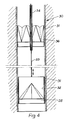
- an underground well 30 is shown as being lined with tubular casing 31.
- a heavy cylindrical lifter shell 32 is suspended on the lower end of a line 33 passing down an axially located tube 34.
- a retrieval device 35 is within the shell 32 .
- the function of the shell 32 is to locate the device 35 axially in the well and to add weight to the device.
- At a higher level in the well 30 are one or more further retrieval devices 36 generally similar to the device 35.
- the number of such further devices 36 is determined by the depth of the well as will appear hereinafter.
- the devices 35 and 36 operate to allow water to be raised from the well without the use of conventional mechanical pumps.
- the device 35 is first lowered upon the line 33 to below the water level and then lifted.
- the projecting members open to allow water to pass axially through the device.
- the members close and water is retained by the device 35 and lifted with it.
- water passes upwards through the vertically fixed devices 36 and is subsequently retained by them at the end of the lifting.
- the retrieval device according to the invention may be used for the recovery of oil after a well reaches an age where natural oil pressure is inadequate to raise the product to the surface.
- the device according to the present invention may for most uses have an overall diameter of between 5 cm and 60 cm, especially between 10 cm and 45 cm.
- the device may be used on the domestic front for mixing purposes, in a manner similar to its use for recovering underground liquid deposits.
Landscapes
- Life Sciences & Earth Sciences (AREA)
- Geology (AREA)
- Engineering & Computer Science (AREA)
- Mining & Mineral Resources (AREA)
- Geochemistry & Mineralogy (AREA)
- Fluid Mechanics (AREA)
- Environmental & Geological Engineering (AREA)
- General Life Sciences & Earth Sciences (AREA)
- Physics & Mathematics (AREA)
- Soil Sciences (AREA)
- Earth Drilling (AREA)
- Lining And Supports For Tunnels (AREA)
- Transition And Organic Metals Composition Catalysts For Addition Polymerization (AREA)
- Vehicle Body Suspensions (AREA)
- Electrical Discharge Machining, Electrochemical Machining, And Combined Machining (AREA)
- Lifting Devices For Agricultural Implements (AREA)
- Iron Core Of Rotating Electric Machines (AREA)
- Ultra Sonic Daignosis Equipment (AREA)
- Mechanical Treatment Of Semiconductor (AREA)
Priority Applications (1)
| Application Number | Priority Date | Filing Date | Title |
|---|---|---|---|
| AT85306407T ATE50620T1 (de) | 1984-09-15 | 1985-09-10 | Rueckholvorrichtung. |
Applications Claiming Priority (2)
| Application Number | Priority Date | Filing Date | Title |
|---|---|---|---|
| GB8423365 | 1984-09-15 | ||
| GB848423365A GB8423365D0 (en) | 1984-09-15 | 1984-09-15 | Sampling device |
Publications (3)
| Publication Number | Publication Date |
|---|---|
| EP0175536A2 true EP0175536A2 (de) | 1986-03-26 |
| EP0175536A3 EP0175536A3 (en) | 1987-02-04 |
| EP0175536B1 EP0175536B1 (de) | 1990-02-28 |
Family
ID=10566778
Family Applications (1)
| Application Number | Title | Priority Date | Filing Date |
|---|---|---|---|
| EP85306407A Expired - Lifetime EP0175536B1 (de) | 1984-09-15 | 1985-09-10 | Rückholvorrichtung |
Country Status (6)
| Country | Link |
|---|---|
| US (1) | US4646843A (de) |
| EP (1) | EP0175536B1 (de) |
| AT (1) | ATE50620T1 (de) |
| DE (1) | DE3576183D1 (de) |
| GB (1) | GB8423365D0 (de) |
| IN (1) | IN165202B (de) |
Cited By (1)
| Publication number | Priority date | Publication date | Assignee | Title |
|---|---|---|---|---|
| EP1674888A3 (de) * | 2004-12-27 | 2010-03-03 | SeaBird Technologies AS | Sensoranordnung und Verfahren zu ihrer Installation und Bewegung |
Families Citing this family (4)
| Publication number | Priority date | Publication date | Assignee | Title |
|---|---|---|---|---|
| NO314954B1 (no) * | 2000-01-28 | 2003-06-16 | Total Catcher Offshore As | Fremgangsmåte og anordning for opphenting av utstyr fra borehull, samt anvendelse derav |
| NO313924B1 (no) * | 2000-11-02 | 2002-12-23 | Agr Services As | Spyleverktöy for innvendig rens av vertikalt stigerör, samt fremgangsmÕte for samme |
| DE102015202836A1 (de) * | 2015-02-17 | 2016-08-18 | Rwe Innogy Gmbh | Vorrichtung und Verfahren zum Entnehmen von Kernproben aus Sedimentformationen |
| CN112814132B (zh) * | 2020-12-31 | 2022-08-16 | 庞喜云 | 一种市政下水道垃圾清理装置 |
Family Cites Families (9)
| Publication number | Priority date | Publication date | Assignee | Title |
|---|---|---|---|---|
| US2649710A (en) * | 1948-12-13 | 1953-08-25 | Clarence R Dale | Oil well flowmeter |
| DE801713C (de) * | 1949-10-29 | 1951-01-22 | Bohrpfahl Com Ges Rudolf Weiss | Kernrohrverschluss fuer Probenehmer mit Kernrohr |
| US2672200A (en) * | 1950-03-01 | 1954-03-16 | Thomas G Patterson | Well bridge |
| US2670800A (en) * | 1950-04-27 | 1954-03-02 | Kendall R Stohn | Junk basket well tool |
| US2646845A (en) * | 1951-08-01 | 1953-07-28 | Zero Hour Bomb Company | Well bridge |
| US2890756A (en) * | 1955-07-29 | 1959-06-16 | Edgar T Murray | Hydraulic type junk basket for wells |
| US3561546A (en) * | 1968-11-12 | 1971-02-09 | Leo Horvitz | Method of and apparatus for underwater geochemical exploration |
| US3807234A (en) * | 1972-08-14 | 1974-04-30 | Trippensee Corp | Core catcher for core samplers |
| US3874465A (en) * | 1973-10-02 | 1975-04-01 | Randolph Co | Coring apparatus |
-
1984
- 1984-09-15 GB GB848423365A patent/GB8423365D0/en active Pending
-
1985
- 1985-09-10 AT AT85306407T patent/ATE50620T1/de not_active IP Right Cessation
- 1985-09-10 DE DE8585306407T patent/DE3576183D1/de not_active Expired - Lifetime
- 1985-09-10 EP EP85306407A patent/EP0175536B1/de not_active Expired - Lifetime
- 1985-09-11 US US06/774,891 patent/US4646843A/en not_active Expired - Fee Related
- 1985-09-13 IN IN651/CAL/85A patent/IN165202B/en unknown
Cited By (1)
| Publication number | Priority date | Publication date | Assignee | Title |
|---|---|---|---|---|
| EP1674888A3 (de) * | 2004-12-27 | 2010-03-03 | SeaBird Technologies AS | Sensoranordnung und Verfahren zu ihrer Installation und Bewegung |
Also Published As
| Publication number | Publication date |
|---|---|
| IN165202B (de) | 1989-08-26 |
| US4646843A (en) | 1987-03-03 |
| EP0175536A3 (en) | 1987-02-04 |
| ATE50620T1 (de) | 1990-03-15 |
| GB8423365D0 (en) | 1984-10-17 |
| DE3576183D1 (de) | 1990-04-05 |
| EP0175536B1 (de) | 1990-02-28 |
Similar Documents
| Publication | Publication Date | Title |
|---|---|---|
| US5082069A (en) | Combination drivepipe/casing and installation method for offshore well | |
| EP3017138B1 (de) | Vorrichtung und verfahren zur kultivierung einer bohrlochoberfläche | |
| US8162081B2 (en) | Force balanced asymmetric drilling reamer and methods for force balancing | |
| CA2337543C (en) | Downhole drilling apparatus and method for use of same | |
| US4368786A (en) | Downhole drilling apparatus | |
| NO319196B1 (no) | Fremgangsmate for utforing av en onsket operasjon nede i et bronnhull | |
| US3840079A (en) | Horizontal drill rig for deep drilling to remote areas and method | |
| US9284807B1 (en) | Retrieval tool | |
| GB2161521A (en) | A process and device for sinking wells | |
| EP0175536B1 (de) | Rückholvorrichtung | |
| US3785690A (en) | Tool for use in removing a fish stuck within a well bore | |
| EP0186317A1 (de) | Verfahren und Vorrichtung zur Verrohrung stark abgelenkter Bohrlöcher | |
| US6269877B1 (en) | Magnetic assembly for use with a downhole casing perforator | |
| EP0628700A2 (de) | Bohrwerkzeug zum Herstellen von Bohrlöchern mit grossem Durchmesser | |
| CN220487494U (zh) | 地质探测扩张器 | |
| Murdoch | Alternative methods for fluid delivery and recovery | |
| US12247485B2 (en) | Rotary steerable system with multiple rows of actuators | |
| US4889194A (en) | Method and a device for deep hole drilling | |
| Gibson et al. | Small Wells Manual: A Manual of Location, Design, Construction, Use and Maintenance | |
| KR960002370Y1 (ko) | 오가드릴머신의 천공토류 배토장치 | |
| US4469182A (en) | Method of installing a casing hanger | |
| RU2109919C1 (ru) | Устройство для отбора проб из шлама в призабойной части скважины | |
| JPH0654076B2 (ja) | 立坑の堀削方法 | |
| JPH0351875B2 (de) | ||
| JPS60126490A (ja) | バケツト型掘削器 |
Legal Events
| Date | Code | Title | Description |
|---|---|---|---|
| PUAI | Public reference made under article 153(3) epc to a published international application that has entered the european phase |
Free format text: ORIGINAL CODE: 0009012 |
|
| AK | Designated contracting states |
Kind code of ref document: A2 Designated state(s): AT BE CH DE FR GB IT LI LU NL SE |
|
| PUAL | Search report despatched |
Free format text: ORIGINAL CODE: 0009013 |
|
| AK | Designated contracting states |
Kind code of ref document: A3 Designated state(s): AT BE CH DE FR GB IT LI LU NL SE |
|
| 17P | Request for examination filed |
Effective date: 19870804 |
|
| 17Q | First examination report despatched |
Effective date: 19890213 |
|
| GRAA | (expected) grant |
Free format text: ORIGINAL CODE: 0009210 |
|
| AK | Designated contracting states |
Kind code of ref document: B1 Designated state(s): AT BE CH DE FR GB IT LI LU NL SE |
|
| REF | Corresponds to: |
Ref document number: 50620 Country of ref document: AT Date of ref document: 19900315 Kind code of ref document: T |
|
| REF | Corresponds to: |
Ref document number: 3576183 Country of ref document: DE Date of ref document: 19900405 |
|
| ITF | It: translation for a ep patent filed | ||
| ET | Fr: translation filed | ||
| PLBE | No opposition filed within time limit |
Free format text: ORIGINAL CODE: 0009261 |
|
| STAA | Information on the status of an ep patent application or granted ep patent |
Free format text: STATUS: NO OPPOSITION FILED WITHIN TIME LIMIT |
|
| 26N | No opposition filed | ||
| PGFP | Annual fee paid to national office [announced via postgrant information from national office to epo] |
Ref country code: AT Payment date: 19910912 Year of fee payment: 7 |
|
| PGFP | Annual fee paid to national office [announced via postgrant information from national office to epo] |
Ref country code: CH Payment date: 19910923 Year of fee payment: 7 |
|
| PGFP | Annual fee paid to national office [announced via postgrant information from national office to epo] |
Ref country code: FR Payment date: 19910924 Year of fee payment: 7 |
|
| PGFP | Annual fee paid to national office [announced via postgrant information from national office to epo] |
Ref country code: SE Payment date: 19910927 Year of fee payment: 7 |
|
| ITTA | It: last paid annual fee | ||
| PGFP | Annual fee paid to national office [announced via postgrant information from national office to epo] |
Ref country code: NL Payment date: 19910930 Year of fee payment: 7 Ref country code: DE Payment date: 19910930 Year of fee payment: 7 |
|
| PGFP | Annual fee paid to national office [announced via postgrant information from national office to epo] |
Ref country code: LU Payment date: 19911018 Year of fee payment: 7 |
|
| PGFP | Annual fee paid to national office [announced via postgrant information from national office to epo] |
Ref country code: BE Payment date: 19911106 Year of fee payment: 7 |
|
| EPTA | Lu: last paid annual fee | ||
| PG25 | Lapsed in a contracting state [announced via postgrant information from national office to epo] |
Ref country code: LU Free format text: LAPSE BECAUSE OF NON-PAYMENT OF DUE FEES Effective date: 19920910 Ref country code: AT Effective date: 19920910 |
|
| PG25 | Lapsed in a contracting state [announced via postgrant information from national office to epo] |
Ref country code: SE Effective date: 19920911 |
|
| PG25 | Lapsed in a contracting state [announced via postgrant information from national office to epo] |
Ref country code: LI Effective date: 19920930 Ref country code: CH Effective date: 19920930 Ref country code: BE Effective date: 19920930 |
|
| BERE | Be: lapsed |
Owner name: VALLALLY CECIL OSBERNE Effective date: 19920930 |
|
| PG25 | Lapsed in a contracting state [announced via postgrant information from national office to epo] |
Ref country code: NL Effective date: 19930401 |
|
| NLV4 | Nl: lapsed or anulled due to non-payment of the annual fee | ||
| PG25 | Lapsed in a contracting state [announced via postgrant information from national office to epo] |
Ref country code: FR Effective date: 19930528 |
|
| REG | Reference to a national code |
Ref country code: CH Ref legal event code: PL |
|
| PG25 | Lapsed in a contracting state [announced via postgrant information from national office to epo] |
Ref country code: DE Effective date: 19930602 |
|
| REG | Reference to a national code |
Ref country code: FR Ref legal event code: ST |
|
| EUG | Se: european patent has lapsed |
Ref document number: 85306407.9 Effective date: 19930406 |
|
| PGFP | Annual fee paid to national office [announced via postgrant information from national office to epo] |
Ref country code: GB Payment date: 19960902 Year of fee payment: 12 |
|
| PG25 | Lapsed in a contracting state [announced via postgrant information from national office to epo] |
Ref country code: GB Free format text: LAPSE BECAUSE OF NON-PAYMENT OF DUE FEES Effective date: 19970910 |
|
| GBPC | Gb: european patent ceased through non-payment of renewal fee |
Effective date: 19970910 |