EP0175552A2 - Flüssigkeitsüberwachungen - Google Patents
Flüssigkeitsüberwachungen Download PDFInfo
- Publication number
- EP0175552A2 EP0175552A2 EP85306480A EP85306480A EP0175552A2 EP 0175552 A2 EP0175552 A2 EP 0175552A2 EP 85306480 A EP85306480 A EP 85306480A EP 85306480 A EP85306480 A EP 85306480A EP 0175552 A2 EP0175552 A2 EP 0175552A2
- Authority
- EP
- European Patent Office
- Prior art keywords
- signals
- station
- circuit
- sensors
- receiver
- Prior art date
- Legal status (The legal status is an assumption and is not a legal conclusion. Google has not performed a legal analysis and makes no representation as to the accuracy of the status listed.)
- Withdrawn
Links
Images



Classifications
-
- G—PHYSICS
- G08—SIGNALLING
- G08B—SIGNALLING SYSTEMS, e.g. PERSONAL CALLING SYSTEMS; ORDER TELEGRAPHS; ALARM SYSTEMS
- G08B19/00—Alarms responsive to two or more different undesired or abnormal conditions, e.g. burglary and fire, abnormal temperature and abnormal rate of flow
-
- G—PHYSICS
- G01—MEASURING; TESTING
- G01N—INVESTIGATING OR ANALYSING MATERIALS BY DETERMINING THEIR CHEMICAL OR PHYSICAL PROPERTIES
- G01N33/00—Investigating or analysing materials by specific methods not covered by groups G01N1/00 - G01N31/00
- G01N33/18—Water
Definitions
- This invention relates to apparatus for and methods of monitoring fluids. More particularly, although not exclusively, the invention is related to apparatus for methods and of monitoring a range of conditions of liquids such as water in a swimming pool, hot tubs, whirlpool or jacuzzi.
- apparatus for monitoring conditions of a fluid comprising a first station incorporating a detector and transmitter assembly including a plurality of conditions sensors, each of which is adapted to monitor one or more conditions of a fluid, receipt circuits adapted to receive signals from the sensors, a radio transmitter circuit, fed from the receipt circuits; and a second station incorporating a receiver and output assembly including a radio decoding circuit for receiving signals from the transmitter circuit, incorporating a sub-circuit for separating and decoding signals from each of the condition sensors, and a sub-circuit for converting these signals to a common voltage range, and an output circuit for translating the signal voltages to appropriate signal values for a visual and/or audio output.
- the first station receipt circuits may include amplifier and offset circuits.
- a method of monitoring fluid conditions by obtaining signals from sensors detecting a plurality of conditions; amplifying such signals and transmitting them via a radio transmitter to a receiver; decoding and separating the signals with respect to the separate elements at the receiver and converting the same into signal voltages; and passing such signal voltages to a visual and/or audio output.
- the second station may include a radio transmitter circuit adapted to receive signals from one or more control circuits and transmit command signals to the first station or elsewhere to operate fluid controlling mechanisms.
- Such fluid controlling mechanisms may comprise a fluid pump or a heater for example.
- radio control of, for example, heaters and pumps for a swimming pool may be provided by a radio control system separate from the second station.
- the transmitter circuit in the first station may be arranged to transmit signals from each of the probe sensors at different frequencies, or in pulse width variations which are emitted from the transmitter and detected and separated by the receiver.
- Appropriate circuits may be provided in the first station for converting the signal voltages from each of the sensors to a common voltage range. Similarly circuits may be provided for converting signals received by the receiver circuit in the second station to a common voltage range for feeding to the visual/audio output circuit.
- the second station may incorporate an appropriate matrix selector such as a keyboard for operator usage for selecting from the plurality of separate signals received from the transmitter for forwarding on to the visual/audio output circuit.
- an appropriate matrix selector such as a keyboard for operator usage for selecting from the plurality of separate signals received from the transmitter for forwarding on to the visual/audio output circuit.
- the output may comprise an LED or LCD unit, and/or may include warning lights and/or warning audio outputs if received signals deviate beyond a predetermined required range.
- sensors may be provided for detecting the pH value of the water, the level of chlorination, the temperature in degrees Centrigade and/or degrees Fahrenheit, and the water clarity.
- the second station may comprise a visual display unit of semi-fixed nature which can be adapted to show one or more of the signals representative of the conditions of the liquid simultaneously, or can comprise a hand held unit adapted to show on a display, such as liquid crystal display, signals representative of each of the conditions to be monitored in turn by depression of an appropriate switch on the unit.
- a visual display unit of semi-fixed nature which can be adapted to show one or more of the signals representative of the conditions of the liquid simultaneously, or can comprise a hand held unit adapted to show on a display, such as liquid crystal display, signals representative of each of the conditions to be monitored in turn by depression of an appropriate switch on the unit.
- the first station includes a plurality of sensors 1, 2, 3, 4 and 5 which are in practice located in a swimming pool.
- Sensor 1 is a pH probe for detecting the pH value of the pool water
- sensor 2 is a selective ion probe for detecting the chlorine level in the water
- sensors 3 and 4 are thermocouples or thermistors for centigrade and fahrenheit temperature measurements
- sensor 5 is an infra-red detector of water clarity. All these detectors operate at somewhat different signal levels, but, typicaly, sensor 1 gives an output of 18 millivolts.
- the analogue output signals from the sensors are fed to circuitry 6 including separate amplifying circuits and offset voltage applying circuits for each sensor, where the analogue input signals are converted to digital voltage signals and a voltage is superimposed upon the voltage signal such as to raise the overall voltages of each signal to the order of 500 microvolts.
- circuitry 6 including separate amplifying circuits and offset voltage applying circuits for each sensor, where the analogue input signals are converted to digital voltage signals and a voltage is superimposed upon the voltage signal such as to raise the overall voltages of each signal to the order of 500 microvolts.
- Each of the outputs is then fed to a transmitting circuit 7 where each of the signals are transmitted via aerial 8 sequentially in pulsed frequencies in encoded chains of pulses.
- Power supply for the circuits from 240 mains voltage is via a stabilised power rectified supply 9 at 12 volts.
- the transmitter has an output of 500 mW operating on 27Khz A M or 35Mhz F M.
- the pulse train is received at aerial 10 and at circuit 11 is decoded into separate signal trains for each of the sensors and transmitted on as amplified signal voltages of varying magnitude between 0 and 500 mv.
- the signals then pass through a selection circuit 12 operated by a keyboard matrix 13 which enables just one set of signals representative of one sensor to pass through an amplifier and smoothing circuit 14 at which a further offset voltage is superimposed to bring the overall voltage within the magnitude of 0 to 2 volts.
- This voltage signal is then passed to a translation circuit 15 where the voltage is converted for display on a liquid crystal or gas plasma/L.E.D. display unit 16. Power for the receiver and output station is provided by a 9v battery 17.
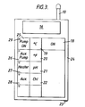
- Figure 3 a illustrates hand held case 24 for a variant of the second station illustrated in Figure 2.
- the case 24 is provided with an on/off switch 18 and keys 19, 20, 21, 22 connected to a keyboard maxtrix for operation of a selection circuit.
- Display unit 16 is located at one end of the case 24 as is aerial 10.
- control keys 25, 26, 27 and 28 are provided under a touch membrane for initiating the radio transmission of operating signals to a pool pump, auxiliary pump, heater and auxiliary heater.
- Each of the keys 25, 26, 27 and 28 incorporates a status lamp 29, indicating the operating condition of the associated mechanism.
- the assembly may be powered by batteries rechargeable via port 23.
- FIG. 4 illustrates a somewhat more elaborate desk top assembly containing the second station.
- this provides a plurality of LCD displays 30, 31 and 32 for display monitoring various swimming pool characteristics such as pH, disinfectant levels, o o and temperature in C or in F.
- Other displays for water clarity pump flow rate, pump pressure rate and power consumption for example can be provided.
- a keyboard 38 is included for programming a computer for control purposes, the computer being connectable via terminal 39, whilst a full computer display may be connected via socket 40.
- o Set points for disinfectant level, ph, C for example may be established by keys 34, 35, 36 and 37 in conjunction with an alpha-numeric display 33 and the computer keyboard 38.
- Sockets 51, 52 and 53 may be provided for probes, ancillary equipment, and for connection to chemical pumps for example.
- the computer may have facility for future projection of pool conditions and states, and may be used for automatic chemical dosing.
- the case may incorporate an alarm.
- power will be from rechargeable batteries, and the device will have a radio transmisson/reception range of 1 Km.
- the circuitry will include pulse coding for individual identification. Temperature range monitors may be o 0 0 0 between -10 C and + 100 C, and 20 F to 240 F. pH variations between 4.00 and 10.00 may be measured, for example.
- Figure 5 shows possible control system for a swimming pool, in which there are provided three alternative controls units: a hand held controller 42; a Desk top controller 43; and a within pool controller 44. These are used for monitoring and signalling by radio transmission to a main control unit 45 located in a pool pump house for example, and at least one localised and specific slave power control unit 46.
- the invention can find most useful application as follows: ship sewage and bridge water systems; drinking water supplies; sewage water monitoring; monitoring emission gases such as in industrial chimneys and exhaust systems; fire monitoring, remote gas leak sensing; and fish farming water monitoring, for example.
Landscapes
- Physics & Mathematics (AREA)
- General Physics & Mathematics (AREA)
- Health & Medical Sciences (AREA)
- Life Sciences & Earth Sciences (AREA)
- Chemical & Material Sciences (AREA)
- Food Science & Technology (AREA)
- Engineering & Computer Science (AREA)
- Medicinal Chemistry (AREA)
- Analytical Chemistry (AREA)
- Biochemistry (AREA)
- General Health & Medical Sciences (AREA)
- Immunology (AREA)
- Pathology (AREA)
- Arrangements For Transmission Of Measured Signals (AREA)
- Investigating Or Analyzing Materials By The Use Of Electric Means (AREA)
Applications Claiming Priority (2)
| Application Number | Priority Date | Filing Date | Title |
|---|---|---|---|
| GB848423369A GB8423369D0 (en) | 1984-09-15 | 1984-09-15 | Monitoring of liquids |
| GB8423369 | 1984-09-15 |
Publications (2)
| Publication Number | Publication Date |
|---|---|
| EP0175552A2 true EP0175552A2 (de) | 1986-03-26 |
| EP0175552A3 EP0175552A3 (de) | 1987-12-16 |
Family
ID=10566782
Family Applications (1)
| Application Number | Title | Priority Date | Filing Date |
|---|---|---|---|
| EP85306480A Withdrawn EP0175552A3 (de) | 1984-09-15 | 1985-09-12 | Flüssigkeitsüberwachungen |
Country Status (6)
| Country | Link |
|---|---|
| US (1) | US4825207A (de) |
| EP (1) | EP0175552A3 (de) |
| AU (1) | AU4744585A (de) |
| ES (1) | ES8706269A1 (de) |
| GB (2) | GB8423369D0 (de) |
| ZA (1) | ZA857052B (de) |
Cited By (11)
| Publication number | Priority date | Publication date | Assignee | Title |
|---|---|---|---|---|
| GB2199955A (en) * | 1987-01-14 | 1988-07-20 | Ograph Limited X | A device for use in monitoring parameters during the processing of a film |
| EP0350049A3 (de) * | 1988-07-06 | 1991-03-20 | Kabushiki Kaisha Toshiba | Verfahren und System zum Erzeugen eines Alarmsignals in einem automatischen chemischen Analysegerät |
| WO1991008530A1 (en) * | 1989-12-04 | 1991-06-13 | Peter Parker | Control apparatus |
| GB2246441A (en) * | 1990-04-17 | 1992-01-29 | Dunlop Ltd | Outfall monitoring |
| FR2689639A1 (fr) * | 1992-04-03 | 1993-10-08 | Inst Francais Du Petrole | Système pour mesurer au moins un paramètre significatif de la teneur en dioxyde de carbone dissous dans un milieu. |
| GB2295232A (en) * | 1994-11-15 | 1996-05-22 | Boghos Awanes Manook | Continuous multi-parameter monitoring of liquids with a novel sensor cleaning and calibration system |
| WO1997018359A1 (en) * | 1995-11-13 | 1997-05-22 | Peter Zosimadis | Wireless temperature monitoring system |
| US5845844A (en) * | 1995-11-13 | 1998-12-08 | Zosimodis; Peter | Wireless temperature monitoring system |
| FR2778463A1 (fr) * | 1998-05-06 | 1999-11-12 | Sagem | Procede et installation de controle d'eau chloree |
| US6059192A (en) * | 1996-04-04 | 2000-05-09 | Zosimadis; Peter | Wireless temperature monitoring system |
| US6536060B1 (en) | 1999-07-27 | 2003-03-25 | Unilever Home & Personal Care Usa Division Of Conopco, Inc. | Method and monitoring device for monitoring a wash process |
Families Citing this family (18)
| Publication number | Priority date | Publication date | Assignee | Title |
|---|---|---|---|---|
| JPH0821154B2 (ja) * | 1987-01-22 | 1996-03-04 | 日東工器株式会社 | 測定デ−タ集計システム |
| US4973957A (en) * | 1987-01-22 | 1990-11-27 | Man Design Co., Ltd. | Data collecting system |
| MY106078A (en) * | 1988-12-26 | 1995-03-31 | Tokyo Tatsuno Kk | System for radio transmission of liquid level data and for converting received data to volume data to be indicated. |
| US5224051A (en) * | 1989-05-19 | 1993-06-29 | Cincinnati Milacron, Inc. | Fluid condition monitoring and controlling system for a metalworking fluid central system |
| US5218304A (en) * | 1992-03-06 | 1993-06-08 | Monsanto Company | Electronic pH and ORP indicator |
| GB2290622B (en) * | 1995-06-13 | 1998-02-25 | Omega Engineering | Radiant wave energy-coupled test meter |
| GB9623116D0 (en) * | 1996-11-06 | 1997-01-08 | Durand Assignees Ltd | Swimming pool management system |
| US6527796B1 (en) * | 2000-01-24 | 2003-03-04 | James A. Magovern | Method and apparatus for burning calories |
| WO2002065960A1 (en) * | 2001-02-16 | 2002-08-29 | Cardiac Assist Technologies, Inc. | Method and apparatus for burning calories |
| US7167087B2 (en) * | 2004-10-20 | 2007-01-23 | Balboa Instruments, Inc. | Remote SPA monitor |
| US20100164709A1 (en) * | 2008-12-29 | 2010-07-01 | Yung-Chih Lin | Apparatus for monitoring water drinking device |
| CN102053139B (zh) * | 2009-10-27 | 2014-06-11 | 中国科学院苏州纳米技术与纳米仿生研究所 | 一种实时的多参数远程水质监测方法 |
| US9476108B2 (en) * | 2013-07-26 | 2016-10-25 | Ecolab Usa Inc. | Utilization of temperature heat adsorption skin temperature as scale control reagent driver |
| FR3023616B1 (fr) * | 2014-07-10 | 2017-08-25 | Bleu Electrique | Procede et dispositif de mesure et d'affichage colorimetriques de donnees physico-chimiques. |
| CN104464249A (zh) * | 2014-12-18 | 2015-03-25 | 重庆多邦科技发展有限公司 | 一种低成本低功耗小体积小系统的遥测终端机 |
| CN104748775A (zh) * | 2015-03-02 | 2015-07-01 | 曾梓航 | 一种环境水状态指示树 |
| EP3702776A3 (de) * | 2019-02-26 | 2020-09-16 | Pentair Water Pool and Spa, Inc. | System und verfahren zur überwachung der wasserqualität |
| USD926610S1 (en) | 2019-05-22 | 2021-08-03 | Pentair Water Pool And Spa, Inc. | Water quality monitor |
Family Cites Families (19)
| Publication number | Priority date | Publication date | Assignee | Title |
|---|---|---|---|---|
| US2675540A (en) * | 1948-06-21 | 1954-04-13 | Bendix Aviat Corp | Multichannel telemetering system |
| US3573817A (en) * | 1968-02-28 | 1971-04-06 | North American Rockwell | Monitoring system |
| US3636544A (en) * | 1970-01-19 | 1972-01-18 | Jorge G Codina | Alarm |
| US3724474A (en) * | 1971-09-20 | 1973-04-03 | Halogen Controls Inc | Apparatus for monitoring and controlling halogen levels in a water treatment system |
| GB1431951A (en) * | 1973-06-01 | 1976-04-14 | Physics Int Co | System for transmission of analogue data over a single trans mission channel from one of a plurality of remote stations to a central station |
| DE2416063C3 (de) * | 1974-04-03 | 1978-03-30 | Erich 3000 Hannover Krebs | Vorrichtung zum Messen und drahtlosen Übertragen von Meßwerten zur Erdoberfläche |
| US4121200A (en) * | 1976-07-22 | 1978-10-17 | Colmenero Gustavo T | Swimming pool alarm system |
| US4154660A (en) * | 1977-08-30 | 1979-05-15 | Delphian Corporation | Method and apparatus for monitoring sulfide in well drilling mud |
| US4160970A (en) * | 1977-11-25 | 1979-07-10 | Sperry Rand Corporation | Electromagnetic wave telemetry system for transmitting downhole parameters to locations thereabove |
| US4187502A (en) * | 1977-12-12 | 1980-02-05 | Beverly Frank O | Swimming pool alarm system |
| DE2807887A1 (de) * | 1978-02-20 | 1979-08-30 | Alusuisse | Verfahren zur uebertragung von messdaten, anwendung des verfahrens sowie anordnung zur ausfuehrung des verfahrens |
| DE2922493A1 (de) * | 1978-06-28 | 1980-01-17 | Dresser Ind | Messgeraeteanlage zum ueberwachen beim bohren eines oelbohrlochs |
| US4404697A (en) * | 1978-08-14 | 1983-09-20 | Intermatic Incorporated | Remote control system for spas |
| US4275382A (en) * | 1979-07-18 | 1981-06-23 | Jannotta Louis J | Apparatus for monitoring and controlling vessels containing liquid |
| DE3107928A1 (de) * | 1981-03-02 | 1982-09-16 | Vdo Adolf Schindling Ag, 6000 Frankfurt | Einrichtung zum beruehrungslosen uebertragen eines zahlenwertes |
| AU8658682A (en) * | 1981-08-07 | 1983-02-10 | Leonard Joseph Genest | Remote sensor telemetering system |
| DE3228938A1 (de) * | 1982-08-03 | 1984-02-16 | Deutsche Tiefbohr-Aktiengesellschaft, 4444 Bad Bentheim | Einrichtung zur fernsteuerung und ueberwachung von bohrlochschliessanlagen |
| FR2538644A1 (fr) * | 1982-12-22 | 1984-06-29 | Serge Garrigou | Systeme de telemesure |
| FR2562601B2 (fr) * | 1983-05-06 | 1988-05-27 | Geoservices | Dispositif pour transmettre en surface les signaux d'un emetteur situe a grande profondeur |
-
1984
- 1984-09-15 GB GB848423369A patent/GB8423369D0/en active Pending
-
1985
- 1985-09-12 GB GB08522608A patent/GB2165126B/en not_active Expired
- 1985-09-12 EP EP85306480A patent/EP0175552A3/de not_active Withdrawn
- 1985-09-13 AU AU47445/85A patent/AU4744585A/en not_active Abandoned
- 1985-09-13 ZA ZA857052A patent/ZA857052B/xx unknown
- 1985-09-13 ES ES546961A patent/ES8706269A1/es not_active Expired
-
1987
- 1987-12-03 US US07/129,334 patent/US4825207A/en not_active Expired - Fee Related
Cited By (15)
| Publication number | Priority date | Publication date | Assignee | Title |
|---|---|---|---|---|
| GB2199955A (en) * | 1987-01-14 | 1988-07-20 | Ograph Limited X | A device for use in monitoring parameters during the processing of a film |
| EP0350049A3 (de) * | 1988-07-06 | 1991-03-20 | Kabushiki Kaisha Toshiba | Verfahren und System zum Erzeugen eines Alarmsignals in einem automatischen chemischen Analysegerät |
| WO1991008530A1 (en) * | 1989-12-04 | 1991-06-13 | Peter Parker | Control apparatus |
| GB2246441A (en) * | 1990-04-17 | 1992-01-29 | Dunlop Ltd | Outfall monitoring |
| GB2246441B (en) * | 1990-04-17 | 1994-08-10 | Dunlop Ltd | Outfall monitoring |
| FR2689639A1 (fr) * | 1992-04-03 | 1993-10-08 | Inst Francais Du Petrole | Système pour mesurer au moins un paramètre significatif de la teneur en dioxyde de carbone dissous dans un milieu. |
| GB2295232A (en) * | 1994-11-15 | 1996-05-22 | Boghos Awanes Manook | Continuous multi-parameter monitoring of liquids with a novel sensor cleaning and calibration system |
| GB2295232B (en) * | 1994-11-15 | 1999-05-05 | Boghos Awanes Manook | Continuous multi-parameter monitoring of liquids with a novel sensor cleaning and calibration system |
| WO1997018359A1 (en) * | 1995-11-13 | 1997-05-22 | Peter Zosimadis | Wireless temperature monitoring system |
| US5845844A (en) * | 1995-11-13 | 1998-12-08 | Zosimodis; Peter | Wireless temperature monitoring system |
| AU706586B2 (en) * | 1995-11-13 | 1999-06-17 | Peter Zosimadis | Wireless temperature monitoring system |
| US6059192A (en) * | 1996-04-04 | 2000-05-09 | Zosimadis; Peter | Wireless temperature monitoring system |
| US6481634B1 (en) | 1996-04-04 | 2002-11-19 | Smart Wave Technologies Inc. | Fluid data monitoring and control system |
| FR2778463A1 (fr) * | 1998-05-06 | 1999-11-12 | Sagem | Procede et installation de controle d'eau chloree |
| US6536060B1 (en) | 1999-07-27 | 2003-03-25 | Unilever Home & Personal Care Usa Division Of Conopco, Inc. | Method and monitoring device for monitoring a wash process |
Also Published As
| Publication number | Publication date |
|---|---|
| ES8706269A1 (es) | 1987-06-01 |
| GB8423369D0 (en) | 1984-10-17 |
| GB8522608D0 (en) | 1985-10-16 |
| AU4744585A (en) | 1986-03-20 |
| EP0175552A3 (de) | 1987-12-16 |
| GB2165126A (en) | 1986-04-03 |
| ZA857052B (en) | 1986-05-28 |
| US4825207A (en) | 1989-04-25 |
| ES546961A0 (es) | 1987-06-01 |
| GB2165126B (en) | 1988-09-28 |
Similar Documents
| Publication | Publication Date | Title |
|---|---|---|
| US4825207A (en) | Monitoring of fluids | |
| KR101621220B1 (ko) | 광 발광식 스마트 수질측정장치 | |
| US6334440B1 (en) | Advanced dive computer that calculates and displays the users breathing parameter and water salinity | |
| US6150944A (en) | Termite detection apparatus | |
| US10048242B2 (en) | Inline water contaminant detector | |
| EP1540612B1 (de) | Swimming-pool-reinigungsvorrichtung mit einrichtung zur onboard-wasseranalyse, datenaufzeichnung und datenübertragung | |
| NO319582B1 (no) | Overvakingssystem med innebygd stromforsyning | |
| WO1988006549A1 (en) | A dive parameter indicating assembly | |
| WO2001014873A1 (en) | Gas detection system and method | |
| US20150082882A1 (en) | System for determining the level of a liquid in a container | |
| KR101526212B1 (ko) | 현장용 스마트 잔류염소 분석기 | |
| KR20190106872A (ko) | 자동 채수기의 원격 제어 시스템 및 제어 방법 | |
| US3794059A (en) | Electronic monitoring control and display apparatus for breathing gas system | |
| US8276890B1 (en) | Pressure monitoring panel for aeration basins | |
| US5085508A (en) | Beam alignment apparatus and method usable with projected beam smoke detector systems | |
| CN214587230U (zh) | 一种矿下瓦斯浓度检测及报警系统 | |
| KR101206834B1 (ko) | 수처리 시스템용 계측기 원격감시제어시스템 | |
| US12003902B2 (en) | System and method for transmitting information | |
| JP2008108038A (ja) | ガス漏れ警報システム | |
| CN119342433A (zh) | 一种基于NB-IoT的户外水质检测仪 | |
| KR20210077937A (ko) | 이동형 수질측정장치 및 이를 이용한 예측시스템 | |
| JPS5555646A (en) | Failure detection system for remote monitor system | |
| KR102279774B1 (ko) | 수질 원격 모니터링 시스템 | |
| KR102365352B1 (ko) | 누액감지센서가 접속된 r형 화재 수신장치 | |
| JP7288181B2 (ja) | データ処理機能付きケーブル、測定システム及び制御システム |
Legal Events
| Date | Code | Title | Description |
|---|---|---|---|
| PUAI | Public reference made under article 153(3) epc to a published international application that has entered the european phase |
Free format text: ORIGINAL CODE: 0009012 |
|
| AK | Designated contracting states |
Kind code of ref document: A2 Designated state(s): BE CH DE FR LI LU SE |
|
| PUAL | Search report despatched |
Free format text: ORIGINAL CODE: 0009013 |
|
| AK | Designated contracting states |
Kind code of ref document: A3 Designated state(s): BE CH DE FR LI LU SE |
|
| 17P | Request for examination filed |
Effective date: 19880613 |
|
| 17Q | First examination report despatched |
Effective date: 19900713 |
|
| STAA | Information on the status of an ep patent application or granted ep patent |
Free format text: STATUS: THE APPLICATION IS DEEMED TO BE WITHDRAWN |
|
| 18D | Application deemed to be withdrawn |
Effective date: 19901124 |
|
| RIN1 | Information on inventor provided before grant (corrected) |
Inventor name: SNELL, JULIEN DARREN |