EP0175559A2 - Fermeture d'armoire - Google Patents
Fermeture d'armoire Download PDFInfo
- Publication number
- EP0175559A2 EP0175559A2 EP85306543A EP85306543A EP0175559A2 EP 0175559 A2 EP0175559 A2 EP 0175559A2 EP 85306543 A EP85306543 A EP 85306543A EP 85306543 A EP85306543 A EP 85306543A EP 0175559 A2 EP0175559 A2 EP 0175559A2
- Authority
- EP
- European Patent Office
- Prior art keywords
- roller shutter
- locker
- closure according
- roller
- locker closure
- Prior art date
- Legal status (The legal status is an assumption and is not a legal conclusion. Google has not performed a legal analysis and makes no representation as to the accuracy of the status listed.)
- Withdrawn
Links
Images

Classifications
-
- E—FIXED CONSTRUCTIONS
- E06—DOORS, WINDOWS, SHUTTERS, OR ROLLER BLINDS IN GENERAL; LADDERS
- E06B—FIXED OR MOVABLE CLOSURES FOR OPENINGS IN BUILDINGS, VEHICLES, FENCES OR LIKE ENCLOSURES IN GENERAL, e.g. DOORS, WINDOWS, BLINDS, GATES
- E06B9/00—Screening or protective devices for wall or similar openings, with or without operating or securing mechanisms; Closures of similar construction
- E06B9/02—Shutters, movable grilles, or other safety closing devices, e.g. against burglary
- E06B9/08—Roll-type closures
- E06B9/11—Roller shutters
-
- B—PERFORMING OPERATIONS; TRANSPORTING
- B60—VEHICLES IN GENERAL
- B60J—WINDOWS, WINDSCREENS, NON-FIXED ROOFS, DOORS, OR SIMILAR DEVICES FOR VEHICLES; REMOVABLE EXTERNAL PROTECTIVE COVERINGS SPECIALLY ADAPTED FOR VEHICLES
- B60J5/00—Doors
- B60J5/10—Doors arranged at the vehicle rear
- B60J5/12—Doors arranged at the vehicle rear slidable; foldable
- B60J5/14—Doors arranged at the vehicle rear slidable; foldable of roller-blind type made of rigid elements
Definitions
- This invention relates to locker closures and in particular to locker closures of the roller shutter type.
- Such locker closures are of particular use in the context of the lockers for storage of fire fighting equipment as provided at the opposed sides and/or rear of a fire fighting vehicle or appliance.
- the builder of a fire fighting vehicle or appliance it is conventional for the builder of a fire fighting vehicle or appliance to manufacture the vehicle body, provided with the lockers therein, and to fit roller shutter locker closures thereto which have been obtained from a specialist roller shutter door manufacturer.
- the roller shutter door manufacturer supplies all of the requisite supplementary parts so as to enable a roller shutter closure to be fitted to each locker.
- the fitting procedure entails the fitting of the spring plates, the position of which must be determined in situ to accommodate the rolled-up shutter, and the individual fitting of the side supports and guide channels, including cam plates therefor, together with any necessary adjustment thereto to allow for correct locking of the shutter when lowered to the locker-closed position.
- the fitting of the cill plate is a further separate operation.
- This fitting operation can take at least It hours per locker and since a vehicle may have seven lockers a considerable labour cost is added to the cost of the vehicle purely in respect of the abovedescribed fitting operation.
- it is necessary to loosen the guide channels and "spring" them outwardly in order to remove the roller shutter. This also is a time consuming operation and the shutter or the fittings therefore may be readily damaged.
- the invention provides a locker closure comprising a roller shutter and fittings therefor, said fittings comprising a pair of spaced guide channels in which said roller shutter may slide longitudinally, and a pair of spaced tie bars securing said guide channels to form a rectangular frame structure in which said roller shutter is mounted.
- Each guide channel may include a bracket to which a respective spring plate for the roller shutter is secured.
- a third tie bar may secure said brackets in spaced disposition.
- Each guide channel may include a removable channel part which is removably attached to the respective bracket.
- each guide channel 3 Secured to each guide channel 3 is a cam plate 14 and nylon cam 15 (only the right hand ones being shown in Fig. 1) which locate and secure the roller shutter 41 in the down or locker closed position, the locks 39 fitted to the bottom rail 21 being operated manually when the shutter 41 is to be opened or secured closed.
- each guide channel 3 is also secured to each guide channel 3 to which a spring plate 4, for receiving an end spigot 35a of the roller 35, is attached.
- each channel 3 is attached to a side support 12 (only the right hand one being shown in Fig. 1) which has a channel formation 12a for receiving a side seal 11.
- An infil strip 13 is also fitted to each side support 12.
- the parts described above are conventional and are supplied to the builder of the fire fighting appliance by the manufacturer of the roller shutter closure 40, together with a Gill plate 18 and its associated infil strip 13 and bottom seal 19.
- the dimensions of such parts are governed by the nominal size of the locker to which they are to be fitted.
- the side supports 12 are fitted to the locker opening and the guide channels 3 and brackets 1, 2 fitted thereto.
- the spring plates 4 are then fitted and the roller shutter 41 on its roller 35 located therein. Fitting of the cam plates 14, cams 15, cill plate 18, top neoprene or brush seal 34 and seal holder 33, which may be of channel section to provide a gutter, then follows.
- These fitting steps are time consuming and are prone to errors leading to malfunction of the roller shutter 41, particularly if the locker opening has not been made accurately in accordance with the nominal dimensions or is not truly rectangular.
- the guide channels 3 are connected at top and bottom by tie bars 20 to form a rectangular frame of the required dimensions.
- the brackets 1, 2 are connected by a third tie bar 20.
- the spring plates 4, roller 35 and roller shutter 41, cam plates 14, cams 15 and cill plate 18 are then fitted to the frame as previously described, together with all seals 11,19 and infil strips 13.
- the correct operation of the roller shutter 41 and locks 39 can be checked by the manufacturer of the shutter closure 40 before it leaves his factory.
- the shutter closure 40 in a completely assembled and operational condition may be transported to the vehicle builder with the roller shutter 41 in the locked position.
- shutter closure 40 require maintenance or repair.
- the entire assembly may be readily removed from the locker opening for the maintenance or repair work to be carried out, put into an operational condition, and then returned to the locker opening, thereby saving considerable vehicle out of service time and maintenance costs.
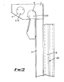
- each guide channel 3 is a guide block channel insert 9, the right hand insert 9 being shown more clearly in Fig. 2.
- the nylon insert 9 is secured by bolts 6 to the bracket 1 and is readily removable therefrom.
- the channel formation formed by insert 9 and the top of guide channel 3 is slightly narrower than that of guide channel 3, so that the shutter 41 runs on the outside of the block 9 and to prevent damage to the end locks 28, spacers 29, and wheel assemblies 25 by the top edge of channel 3 due to any slight misalignment between the channel formations.
- the length of the insert 9 is at least equal to the height of the bottom rail 21 so that when the roller shutter 41 is rolled onto roller 35 with the bottom rail 21 in its uppermost position, removal of the inserts 9 enables the roller shutter 41 and roller 35 to be removed rearwardly and upwardly together from the surrounding frame. After the necessary maintenance or repair of the roller shutter 41 has been effected, it may be rolled onto roller 35 and replaced in the frame, spigots 35a being slid into spring plates 4 and the bottom rail 21 being disposed at the top of the guide channels 3. Inserts 9 are then replaced and secured to brackets 1,2 to complete the channel formation and restore the shutter closure to its fully operational condition.
- a pin (not shown) is inserted into the coiled roller 35 before removal thereof to maintain the spring tension.
- the pin is removed after the roller 35 and shutter 41, and inserts 9, have been replaced.
Landscapes
- Engineering & Computer Science (AREA)
- Structural Engineering (AREA)
- Mechanical Engineering (AREA)
- Architecture (AREA)
- Civil Engineering (AREA)
- Operating, Guiding And Securing Of Roll- Type Closing Members (AREA)
- Specific Sealing Or Ventilating Devices For Doors And Windows (AREA)
- Housing For Livestock And Birds (AREA)
Applications Claiming Priority (2)
| Application Number | Priority Date | Filing Date | Title |
|---|---|---|---|
| GB8424017 | 1984-09-21 | ||
| GB848424017A GB8424017D0 (en) | 1984-09-21 | 1984-09-21 | Locker closure |
Publications (2)
| Publication Number | Publication Date |
|---|---|
| EP0175559A2 true EP0175559A2 (fr) | 1986-03-26 |
| EP0175559A3 EP0175559A3 (fr) | 1987-02-04 |
Family
ID=10567124
Family Applications (1)
| Application Number | Title | Priority Date | Filing Date |
|---|---|---|---|
| EP85306543A Withdrawn EP0175559A3 (fr) | 1984-09-21 | 1985-09-16 | Fermeture d'armoire |
Country Status (2)
| Country | Link |
|---|---|
| EP (1) | EP0175559A3 (fr) |
| GB (2) | GB8424017D0 (fr) |
Cited By (3)
| Publication number | Priority date | Publication date | Assignee | Title |
|---|---|---|---|---|
| GB2199608A (en) * | 1986-10-10 | 1988-07-13 | Rotalac Plastics | Shutters |
| US5002693A (en) * | 1987-03-23 | 1991-03-26 | Sumitomo Chemical Company, Limited | Novel optically active benzene derivatives, process for producing the same and liquid-crystalline substances containing said derivatives as active ingredient and optical switching elements |
| AU609440B2 (en) * | 1988-01-07 | 1991-05-02 | Albrun Holdings Pty Ltd | Roller shutter which can be fitted to the inside of window openings |
Family Cites Families (6)
| Publication number | Priority date | Publication date | Assignee | Title |
|---|---|---|---|---|
| FR1299677A (fr) * | 1961-06-15 | 1962-07-27 | Fermetures F M B | Perfectionnements aux stores pour fenêtres |
| GB1012276A (en) * | 1963-02-04 | 1965-12-08 | Dover Roller Shutters Ltd | Improved roller shutter |
| GB1222203A (en) * | 1967-01-30 | 1971-02-10 | Dover Roller Shutters Ltd | Improvements in or relating to roller shutters |
| US4018259A (en) * | 1971-01-25 | 1977-04-19 | Dynamit Nobel Aktiengesellschaft | Jalousie element |
| US3840061A (en) * | 1971-01-25 | 1974-10-08 | G Herms | Jalousie element |
| US3672492A (en) * | 1971-02-09 | 1972-06-27 | North American Door Corp | Factory-assembled overhead door |
-
1984
- 1984-09-21 GB GB848424017A patent/GB8424017D0/en active Pending
-
1985
- 1985-07-15 GB GB08517774A patent/GB2164693B/en not_active Expired
- 1985-09-16 EP EP85306543A patent/EP0175559A3/fr not_active Withdrawn
Cited By (4)
| Publication number | Priority date | Publication date | Assignee | Title |
|---|---|---|---|---|
| GB2199608A (en) * | 1986-10-10 | 1988-07-13 | Rotalac Plastics | Shutters |
| GB2199608B (en) * | 1986-10-10 | 1990-04-11 | Rotalac Plastics | Slatted shutters |
| US5002693A (en) * | 1987-03-23 | 1991-03-26 | Sumitomo Chemical Company, Limited | Novel optically active benzene derivatives, process for producing the same and liquid-crystalline substances containing said derivatives as active ingredient and optical switching elements |
| AU609440B2 (en) * | 1988-01-07 | 1991-05-02 | Albrun Holdings Pty Ltd | Roller shutter which can be fitted to the inside of window openings |
Also Published As
| Publication number | Publication date |
|---|---|
| GB8517774D0 (en) | 1985-08-21 |
| GB2164693A (en) | 1986-03-26 |
| GB8424017D0 (en) | 1984-10-31 |
| GB2164693B (en) | 1987-07-01 |
| EP0175559A3 (fr) | 1987-02-04 |
Similar Documents
| Publication | Publication Date | Title |
|---|---|---|
| US4219971A (en) | Pocket window | |
| US5347775A (en) | Hurricane shutters for windows | |
| US7263808B2 (en) | Adjustable rail assembly for exterior door still assembly and components for the same | |
| DE69401211T2 (de) | Hubgaragentoraufhänger | |
| US7963436B2 (en) | Cluster box mail delivery unit having security features | |
| US4639971A (en) | Door hinge shim | |
| EP0230083A1 (fr) | Système pour la construction des caissons de climatisation d'air et méthode pour leur montage | |
| GB2163398A (en) | Pan length/line pan for a conveyor | |
| US2477942A (en) | Window | |
| EP0175559A2 (fr) | Fermeture d'armoire | |
| CN106559965A (zh) | 用于安装设备的服务器机架系统 | |
| US4837996A (en) | Glass facade | |
| US4517767A (en) | Mine ventilation door | |
| US6067754A (en) | Basement window | |
| US7779577B2 (en) | Sash reinforcement for an operator window | |
| GB2212545A (en) | Glazing system | |
| US2740998A (en) | Window structures | |
| US3024501A (en) | Storm door assembly | |
| WO2003089747A1 (fr) | Ensemble d'encadrement et procede destines a installer une vitre dans une ouverture de panneau | |
| EP1167667B1 (fr) | Elément de ferrure pour une fenêtre ou une porte et méthode d'assemblage | |
| US4224772A (en) | Window construction | |
| US2643422A (en) | Window construction | |
| US2207772A (en) | Window construction | |
| EP4610455A1 (fr) | Poteau de portail | |
| US1379227A (en) | Combination screen and storm-sash |
Legal Events
| Date | Code | Title | Description |
|---|---|---|---|
| PUAI | Public reference made under article 153(3) epc to a published international application that has entered the european phase |
Free format text: ORIGINAL CODE: 0009012 |
|
| AK | Designated contracting states |
Kind code of ref document: A2 Designated state(s): AT BE CH DE FR IT LI LU NL SE |
|
| PUAL | Search report despatched |
Free format text: ORIGINAL CODE: 0009013 |
|
| AK | Designated contracting states |
Kind code of ref document: A3 Designated state(s): AT BE CH DE FR IT LI LU NL SE |
|
| 17P | Request for examination filed |
Effective date: 19870729 |
|
| 17Q | First examination report despatched |
Effective date: 19880325 |
|
| STAA | Information on the status of an ep patent application or granted ep patent |
Free format text: STATUS: THE APPLICATION HAS BEEN WITHDRAWN |
|
| 18W | Application withdrawn |
Withdrawal date: 19880722 |
|
| RIN1 | Information on inventor provided before grant (corrected) |
Inventor name: DOVER, FREDERICK GEORGE |