EP0175565A1 - Dispositif pour la couture des étiquettes sur des poches de vêtements - Google Patents
Dispositif pour la couture des étiquettes sur des poches de vêtements Download PDFInfo
- Publication number
- EP0175565A1 EP0175565A1 EP85306586A EP85306586A EP0175565A1 EP 0175565 A1 EP0175565 A1 EP 0175565A1 EP 85306586 A EP85306586 A EP 85306586A EP 85306586 A EP85306586 A EP 85306586A EP 0175565 A1 EP0175565 A1 EP 0175565A1
- Authority
- EP
- European Patent Office
- Prior art keywords
- sewing machine
- sleeve
- axis
- torque tube
- tube
- Prior art date
- Legal status (The legal status is an assumption and is not a legal conclusion. Google has not performed a legal analysis and makes no representation as to the accuracy of the status listed.)
- Withdrawn
Links
Images



Classifications
-
- D—TEXTILES; PAPER
- D05—SEWING; EMBROIDERING; TUFTING
- D05B—SEWING
- D05B3/00—Sewing apparatus or machines with mechanism for lateral movement of the needle or the work or both for making ornamental pattern seams, for sewing buttonholes, for reinforcing openings or for fastening articles, e.g. buttons, by sewing
- D05B3/12—Sewing apparatus or machines with mechanism for lateral movement of the needle or the work or both for making ornamental pattern seams, for sewing buttonholes, for reinforcing openings or for fastening articles, e.g. buttons, by sewing for fastening articles by sewing
- D05B3/20—Sewing apparatus or machines with mechanism for lateral movement of the needle or the work or both for making ornamental pattern seams, for sewing buttonholes, for reinforcing openings or for fastening articles, e.g. buttons, by sewing for fastening articles by sewing labels
Definitions
- the present invention relates to a new work piece handling apparatus for sewing machines and in particular to automatic apparatus for sewing labels, patches or emblems on pockets, sleeves, pant legs, small bags, sacks, pouches or other work pieces of generally tubular construction.
- the maker's label can usually be found on the inside pocket. It is customary to affix the label only after the garment is completed. In the past, the labels were typically hand sewn through the layer of material which forms the pocket. The excess labor cost for sewing on labels in this manner was, of course, disproportionately high.
- the primary object of the present invention is to automate the pocket label sewing operation for a finished garment.
- a clamp-type work feeder includes an articulated, rotatable, telescoping tube carriage which is mechanized to move parallel to the lower arm and to rotate about the axis of the lower arm in accordance with a stored stitch program.
- a cylinder-actuated clamp mechanism facilitates insertion of the work and allows full peripheral stitching around a label or patch while holding it in place and rotating and translating it without unduly obstructing the operator's view or access to the stitching area and without increasing the dimensions of the end of the lower arm.
- an existing programmable sewing machine with a two axis ball carriage driven sewing table is converted to rotate about the axis of the end of the lower arm in accordance with the normal command to move in a direction perpendicular to the drive shaft.
- a plurality of articulated coaxial tubes or sleeves are mounted about the lower needle (or "hook") drive shaft.
- the front sleeve carries a two-part pivoting clamp mechanism actuated by a plurality of cylinders mounted to the outer rear tube body.
- the clamp assembly includes a label locator frame and a shoe which engages the middle of the label inside the frame. The shoe is connected via a U-shaped yoke which flips from one orientation to the other to allow the upper needle to complete the full 360° periphery of the label.
- a Mitsubishi PLK-0604 programmable sewing machine is selected for conversion based upon a number of existing features.
- This industrial grade lock stitch machine comes with a feed table to which the work can be clamped for movement in a plane.
- the work table is carried by means of an X-Y ball carriage assembly which can be driven in the Y direction parallel to the axis of the lower needle drive shaft, i.e., parallel to the lower arm and in the X direction horizontal and perpendicular to the Y axis.
- the X and Y carriage components are driven by timing belts which in turn are driven by stepper motors actuated electronically in accordance with a stored stitch program.
- the stitch program is stored in an electronically programmable read only memory (EPROM) in a removable cartridge. New stitch programs are entered electronically in the EPROM.
- EPROM electronically programmable read only memory
- the Mitsubishi machine is modified in accordance with the invention by replacing the planar X-Y carriage assembly with an articulated tube carriage mounted around the hook shaft and by attaching a special clamp assembly to the tube carriage.
- the hook shaft is changed from oscillating motion to continuous rotation, and the throat plate and lower arm end are made cylindrical.
- the result is a machine in which the same programmable stitch system can now be used to perform any desired stitching operation on a cylindrical surface.
- the dimensions of the end of the arm which carries the lower hook and bobbin assembly are small enough that an inside pocket of a sport coat, for example, can be slipped over the end and clamped in place for sewing a label completely automatically in a few seconds time.
- the stitch by programming the stitch as an open zig-zag stitch over the edge of the label, if desired, the label will retain a hand-sewn appearance.
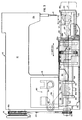
- Figs. 1-4 show the converted machine with the articulated tube carriage for translational and rotational motion.
- the basic Mitsubishi machine 10 displays the conventional U-shaped sewing machine configuration comprising an upper horizontal arm 12 and stitching head 12a carrying at least one reciprocating upper needle 14.
- a hand wheel 16 connected to the upper needle drive shaft extends from the other end of the upper arm 12.
- Hand wheel 16 is equipped with a coaxial drive pulley 16a which is belt-driven by an auxiliary electric motor (not shown).
- the upper arm 12 is supported on upright portion 18 on top of a generally rectangular base 20.
- a relatively short arm 21 extends horizontally from the base 20 parallel to the upper arm and terminates in a nose-like cylindrical housing 22.
- the housing 22 includes a bobbin and a rotating or oscillating hook, driven via a hook shaft 24 which extends parallel to the upper arm.
- the hook shaft 24 is journalled in bearings 26 and 28 mounted as shown through an opening at the back of the base 20 and, on the other end, in the housing 22.
- the hook shaft 24 rotates a hook shown in phantom at 30 in Fig. 3 which carries a second thread supplied by the bobbin (not shown) which engages the thread loop produced by the penetrating upper needle 14 to form a lock stitch in the conventional manner.
- the upper needle 14 whose path is shown diagrammatically in Fig. 3 extends through an opening in a cylindrical throat plate 32 covering the top of the housing 22.
- the hook shaft 24 is driven by linkages in the upright portion 18 and base portion 20 which cause the hook shaft to oscillate back and forth.
- a reverse belt drive is implemented as shown in Figs. 3 and 4 to impart counter-rotation to the hook shaft 24.
- a timing belt pulley is mounted at 16b on the hand wheel assembly.
- two idler pulleys 34 and 36 (Fig. 3) are mounted substantially coplanarly with the pulley 38 on the end of the hook shaft 24.
- Idler pulley 36 is mounted conventionally on bracket 40 pivotally mounted to the base at 42 and adjustable by means of a bolt threaded into the base through slot 44.
- the timing belt 46 for the hook shaft goes down from the hand wheel timing belt pulley 16b around the outside of idler pulley 34 and then runs approximately horizontally over to the adjustable idler pulley 36 and after almost circumnavigating the pulley 36, the outside of the belt 46 passes around the hook shaft pulley 38 and back up to the hand wheel pulley 16b.
- the Mitsubishi PLK-0604 comes with a pair of independent stepper motors which control X and Y translation of the work table in the original machine.
- the Y-drive mechanism 50 (the Y direction being parallel to the axis a of the hook shaft 24) comprises a pair of pulleys 52 and 54 mounted on brackets as shown and carrying a timing belt loop 56.
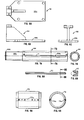
- the bottom surface of the timing belt 56 is clamped to a Y-motion bracket 58 shown in more detail in Figs. 6A-C.
- Flat lower plate or shoe 58a of the Y-motion bracket is rigidly attached to a pair of depending ring-shaped, Y-motion brackets 60 and 62 which serve as bearing caps.
- Inside the brackets 60 and 62 are annular bearings through which the reduced diameter end 64a of the Y-motion torque tube 64 is journalled.
- Bearing bracket 62 abuts the shoulder 64c (Fig. 7A) between the different diameter portions of the torque tube 64.
- the left-hand end of the reduced diameter portion 64a of the Y-motion torque tube which extends through the bearing cap 60 has a groove 64b which receives a snap ring to secure the shaft axially to the Y-motion bracket 58.
- a cylindrical bearing spacer or bushing 66 occupies the space between the bearing brackets 60 and 62 and is slidably received over torque tube end 64a.
- the axis c of the torque tube is slightly lower than the axis a of the hook shaft 24 as shown in Fig. 3.
- the function of the bearing brackets 60 and 62 is to drive the Y torque tube 64 in either axial direction.
- torque tube 64 is tubular and hollow over its entire length so that the hook shaft 24 can extend through the torque tube to the bobbin housing 22.
- the elongated end 64d of the Y torque tube extends over the hook shaft 24 toward the end 22 of the lower arm.
- the outside of portion 64d of the torque tube (Fig. 7A) has a pair of opposed rectangular recesses 64e defined axially along each side. These recesses each receive a Y-motion ball guide or track 70 as shown in Figs. 8A and 8B.
- An X-motion torque tube 72 (Figs. 9A, 9B) of larger diameter than the Y-motion torque tube 64 is received coaxially over the portion 64d of the Y torque tube.
- the X-motion torque tube has opposed recesses 72a formed axially on the inside wall. These recesses 72a receive ball guides similar to ball guides 70 on Y-torque tube 64.
- the ball guides in the recesses 72a extend along the length of the X-motion torque tube 72 and mate with the outside ball guides on the inner Y torque tube 64 in a telescoping manner to form the ball carriage.
- the ends of reduced diameter of the X-motion torque tube as shown in Fig.
- An outer clamp body tube (Figs. 3, 11A and 11B) in the form of an elongated cylindrical shell with cut-away portions for clearance is mounted on the Y-motion torque tube by means of rear support bracket 84 and front clamp support bracket 86 (Fig. 10A). Brackets 84 and 86 space the main body tube 82 coaxially with the Y-torque tube so that it covers the bearing caps 74 and 76 as well as the driven pulley 80.
- the front support bracket 86 as shown in Fig. 10A, is composed of two annular sectors. The part which supports the outer main body tube 82 is the larger sector 86a. Bracket 84 is essentially identical to portion 86a of bracket 86.
- the portion 86b of reduced radius supports a cantilevered bottom clamp tube 88 with portions cut away for clearance as shown in Fig. 12A.
- the right-hand end of bottom clamp tube 88 fits coaxially over the end of housing 22 and is rotatable thereon.
- the axis of rotation of the entire tube carriage assembly coincides with the axis of the cylindrical housing 22.
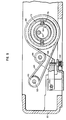
- the X-motion drive mechanism for rotating the tube assembly of Fig. 3 is shown in detail in Figs. 1, 2 and 5.
- An X-motion drive pulley 90 is carried on the end of the X-motion stepper motor drive shaft 92.
- Drive pulley 90 carries a timing belt 94 which goes around driven pulley 80 affixed to the rotatable X-torque tube 72.
- a spring-loaded tensioning idler pulley 96 is rotatably mounted on the end of bracket 98 which is pivoted at 100 on a mounting block affixed to the floor of the base 20, as shown in Fig. 5.
- Tension spring 102 between bracket 98 and the floor urges the bracket 98 downward to keep the timing belt 94 taut.
- the X-torque tube 72 rotates carrying with it the Y-torque tube which is rotationally fixed to but axially slidable within the X tube, along with the outer clamp tube body 82 and the bottom clamp tube 88.
- clamp tubes 82 and 88 also travel in the Y direction with the Y-torque tube when the Y stepper motor is actuated.
- the notch or window w in the upper front portion of bottom clamp tube 88 in Fig. 3 and Fig. 12A represents the nominal axial length of the stitching area.
- the dimensions of the window w preferably correspond to the label size.
- the Y-tube may move the bottom clamp 88 out to 88', a distance approximately equal to the length of the window w, and still keep the penetrating upper needle 14 within the window w as indicated by dashed line 14'.
- a special cylinder-actuated clamp assembly clamps the pocket of the garment firmly to the lower clamp tube 88 over window w by means of a pivoting two-part clamp.
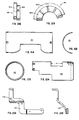
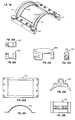
- the label locating clamp 110 is in the form of a thin arcuate rectangular metal frame which sits just inside the window w to press the work against the throat plate as shown in Figs. 13, 18A and 18B.
- the clamp 110 is bolted to two side bars 112 which lie against the outer surface of the lower clamp tube 88 substantially parallel to the c axis. Side bars 112 are also connected by optional arcuate metal straps 114 which extend along the edge of the window w over the lower clamp tube 88.
- the inside of frame 110 may be cut away or relieved so as to only contact the label at a few points, e.g., two at each corner, so that a zig-zag stitch may be made over the edge of the label.
- each side bar l12 is pivotally connected to the front end of a respective arm l16, 118.
- the left-hand arm 118 is shown in detail in Figs. 15A and 15B.
- the right-hand arm is identical but reversed.
- the arms 116 and 118 are bolted to the bottom of an upside down T-shaped connecting bracket 120 pivotally connected to a clevis 122 (Fig. 13) which is attached to cylinder plunger 124 with a cylinder stop 126 in between.
- Plunger 124 is actuated by means of a single acting spring return pneumatic cylinder 128.
- Arms 116 and 118 have aligned through holes 116a and 118a which receive an axle pin.
- the pin passes through a pivot block 130 (Figs. 13, 16A, 16B) which is brazed to the surface of the lower clamp tube 88.
- arms 116 and 118 are pivotally connected to a fixed point on the rear surface of the lower clamp tube 88.
- an arcuate shoe 132 (Figs. 13, 19A, 19B) is pivotally mounted on the end of U-shaped link or yoke shaft 134.
- the yoke shaft 134 is rigidly connected to capstan 136 by means of an axle 138 which is journalled in swivel block 140 (Figs. 17A, 17B).
- Swivel block 140 has a lower through hole 140a which receives the same axle or pin which extends through the arms 116 and 118 so that the swivel block 140 is also pivoted at the same point to the clamp tube 88.
- the upper rear corner of the swivel block 140 is pivotally connected to clevis 142 connected to the plunger 144 of a second pneumatic cylinder 146.
- a cylinder stop 148 is inserted between the clevis 142 and the cylinder 146 limiting the travel of the plunger 144.
- Swivel block 140 carrying the shoe 132, and arms 116 and 118 carrying the label clamp 110 are both pivotally mounted to the clamp tube 88, but are separately actuated by cylinders 146 and 128, respectively, via pneumatic lines energized by a foot treadle (not shown).
- the rear ends of these cylinders are pivotally connected to a cylinder pivot block 150 which is brazed or otherwise secured to the surface of the outer clamp tube body 82.
- Capstan 136 has a hollow front end which receives a torsion spring 152, one end of which is secured in a slot as shown.
- the torsion spring serves to spring bias the yoke 134 to the position shown in Fig. 13.
- the yoke 134 may be rotated or flipped about the axis of the axle 138 to the other side out of the stitch path to allow stitching to be completed.
- the capstan 136 is rotated with a cable 160 (Fig. 14) which goes around the pulley-like end 136a of the capstan.
- the cable 160 goes around an idler pulley 162 mounted to the bottom clamp tube 88 on bracket 164 to a third pneumatic cylinder 166 mounted to one side of the main outer clamp body 82 on block 168.
- the end of the cable 160 is connected to the cylinder plunger by cable anchor block 170 (Fig. 13).
- Actuating the third cylinder 166 causes the plunger to be retracted pulling the cable 160 and rotating the capstan 136 so that the U-shaped yoke 134 flips over to the other side.
- Cylinder 166 is a double-acting cylinder powered only on one end so that the return spring action, which has the effect of pulling the plunger out, is carried out by the torsion spring 152 inside the capstan 136 to return the yoke 134 to the position shown in Fig. 13.
- cylinders 128 and 146 are actuated to retract their respective plungers in order to pivot the shoe 132 and clamp 110 upwards by as little as a half an inch to allow the work to be slipped over the end of the lower arm, i.e., over the right-hand end of the lower clamp tube 88 as shown in Fig. 3.
- the inside pocket of the coat would be slipped over the end of tube 88 over the window w.
- the label if not tacked on beforehand, would be located properly on the pocket inside the window area.
- cylinders 128 and 146 are deactuated and the spring return of the cylinders pivots the clamps into position firmly grasping the garment pocket and the label.
- the stitching begins at a preselected point or "origin" along the periphery of the label.
- the stitching may begin at a point inside the U-shaped yoke 134 as shown by needle position 14' in Fig. 13. From this position, the work is fed so that the stitching proceeds around the periphery of the label.
- the third cylinder 166 is energized to flip the yoke 134. Stitching meanwhile proceeds around the label and crosses the point where it began so as to slightly overlap the stitching, thus completing the 360° stitching pattern.
- the stitching needles stop, but the stepper motors continue to feed so that the carriage is returned to the origin for the next sewing operation.
- the cylinders 128 and 146 are simultaneously actuated to raise the clamps to allow the finished garment to be removed.
- the embodiment of the foregoing description increases the speed of stitching labels on inside coat pockets while retaining a hand sewn look.
- Using the same X and Y stepper motors as in the original planar table feed machine permits the use of the same programmable cartridge system to design stitch patterns for a variety of labels, patches, emblems or embroidery without modifying the basic operation of the standard machine.
- the axis of the articulated tube carriage assembly is offset from the axis of the hook shaft, but by design coincides with the axis of the end of the lower arm which houses the bobbin and hook mechanism.
- the spring-loaded, dual clamp system travels with the outer tube body of the rotatable telescoping carriage.
Landscapes
- Engineering & Computer Science (AREA)
- Textile Engineering (AREA)
- Sewing Machines And Sewing (AREA)
Applications Claiming Priority (2)
| Application Number | Priority Date | Filing Date | Title |
|---|---|---|---|
| US06/652,174 US4730566A (en) | 1984-09-18 | 1984-09-18 | Automatic pocket label stitcher |
| US652174 | 1996-05-23 |
Publications (1)
| Publication Number | Publication Date |
|---|---|
| EP0175565A1 true EP0175565A1 (fr) | 1986-03-26 |
Family
ID=24615796
Family Applications (1)
| Application Number | Title | Priority Date | Filing Date |
|---|---|---|---|
| EP85306586A Withdrawn EP0175565A1 (fr) | 1984-09-18 | 1985-09-17 | Dispositif pour la couture des étiquettes sur des poches de vêtements |
Country Status (3)
| Country | Link |
|---|---|
| US (1) | US4730566A (fr) |
| EP (1) | EP0175565A1 (fr) |
| JP (1) | JPS61179188A (fr) |
Cited By (3)
| Publication number | Priority date | Publication date | Assignee | Title |
|---|---|---|---|---|
| EP0350463A1 (fr) * | 1988-07-05 | 1990-01-10 | St Automations S.R.L. | Station de couture automatique de rembourrage d'épaule |
| US7168379B2 (en) | 2002-09-26 | 2007-01-30 | Brother Kogyo Kabushiki Kaisha | Sewing machine |
| EP2309047A4 (fr) * | 2008-06-06 | 2015-06-17 | Midori Anzen Co Ltd | Machine à coudre |
Families Citing this family (11)
| Publication number | Priority date | Publication date | Assignee | Title |
|---|---|---|---|---|
| DE3628624A1 (de) * | 1986-08-22 | 1988-02-25 | Union Special Gmbh | Ausrichteinrichtung zum kantengerechten, selbsttaetigen ausrichten zu benaehender schlauchfoermiger naehgutteile fuer naehmaschinen |
| US4998964A (en) * | 1990-03-16 | 1991-03-12 | Ultramatic Embroidery Machine Company | Computer controlled embroidery machine for embroidering on curved surfaces and attachment therefor |
| US5501163A (en) * | 1991-11-21 | 1996-03-26 | Zks-Stickmaschinen Gesellschat Mit Beschrankter Haftung | System for holding a tubular workpiece in an embroidery machine |
| GB2280911B (en) * | 1993-08-13 | 1996-10-23 | Union Special Gmbh | Sewing machine for sewing a workpiece binding |
| JP3448156B2 (ja) * | 1996-05-11 | 2003-09-16 | ブラザー工業株式会社 | 縫製装置の布送り装置 |
| US5896295A (en) * | 1996-09-10 | 1999-04-20 | Brother Kogyo Kabushiki Kaisha | Embroidering apparatus and method |
| DE19801586A1 (de) | 1998-01-19 | 1999-07-22 | Daimler Chrysler Ag | Anordnung zum Betreiben eines Transportsystems mit einem magnetischen Schwebefahrzeug |
| US6401641B1 (en) * | 2000-05-10 | 2002-06-11 | Toshiharu Tom Miyano | Apparatus and method for producing a pattern on a piece of material |
| US8128683B2 (en) * | 2004-07-21 | 2012-03-06 | Aesculap & Co. Kg | Longitudinally flexible textile vascular prosthesis |
| JP2014046029A (ja) * | 2012-08-31 | 2014-03-17 | Brother Ind Ltd | ミシン |
| WO2018195442A1 (fr) * | 2017-04-21 | 2018-10-25 | Los Angeles Biomedical Research Institute At Harbor-Ucla Medical Center | Greffes d'endoprothèse, mandrins et leurs procédés d'utilisation |
Citations (3)
| Publication number | Priority date | Publication date | Assignee | Title |
|---|---|---|---|---|
| FR380577A (fr) * | 1907-08-06 | 1907-12-12 | Veit Swoboda | Appareil à broder des bas |
| US3650231A (en) * | 1969-08-11 | 1972-03-21 | Louis E Tinari | Rotatable work support for a sewing machine |
| EP0150971A2 (fr) * | 1984-02-02 | 1985-08-07 | Kabushikikaisha Barudan | Gabarit cylindrique pour tendre les ouvrages tubulaires à broder |
Family Cites Families (6)
| Publication number | Priority date | Publication date | Assignee | Title |
|---|---|---|---|---|
| FR2137932B1 (fr) * | 1971-05-18 | 1973-07-13 | Webber Edward | |
| IT1096663B (it) * | 1978-06-15 | 1985-08-26 | Rockwell Rimoldi Spa | Apparecchiatura per applicare un elastico ad anello su un indumento tubolare |
| US4506611A (en) * | 1979-10-22 | 1985-03-26 | Hitco | Three-dimensional thick fabrics and methods and apparatus for making same |
| DE8302034U1 (de) * | 1983-01-26 | 1983-07-14 | Pfaff Industriemaschinen Gmbh, 6750 Kaiserslautern, De | Vorrichtung zum bearbeiten der umfangskanten von roehrenfoermigen kleidungsstuecken, z.b. roecken und kleidern |
| DE3312317C2 (de) * | 1983-04-06 | 1985-02-07 | Dürkoppwerke GmbH, 4800 Bielefeld | Nähmaschine mit einer Spannvorrichtung für schlauchförmiges Nähgut |
| US4665848A (en) * | 1984-02-13 | 1987-05-19 | Levi Strauss & Co. | Method and apparatus for automatically hemming garments |
-
1984
- 1984-09-18 US US06/652,174 patent/US4730566A/en not_active Expired - Fee Related
-
1985
- 1985-09-17 EP EP85306586A patent/EP0175565A1/fr not_active Withdrawn
- 1985-09-18 JP JP60206185A patent/JPS61179188A/ja active Pending
Patent Citations (3)
| Publication number | Priority date | Publication date | Assignee | Title |
|---|---|---|---|---|
| FR380577A (fr) * | 1907-08-06 | 1907-12-12 | Veit Swoboda | Appareil à broder des bas |
| US3650231A (en) * | 1969-08-11 | 1972-03-21 | Louis E Tinari | Rotatable work support for a sewing machine |
| EP0150971A2 (fr) * | 1984-02-02 | 1985-08-07 | Kabushikikaisha Barudan | Gabarit cylindrique pour tendre les ouvrages tubulaires à broder |
Cited By (3)
| Publication number | Priority date | Publication date | Assignee | Title |
|---|---|---|---|---|
| EP0350463A1 (fr) * | 1988-07-05 | 1990-01-10 | St Automations S.R.L. | Station de couture automatique de rembourrage d'épaule |
| US7168379B2 (en) | 2002-09-26 | 2007-01-30 | Brother Kogyo Kabushiki Kaisha | Sewing machine |
| EP2309047A4 (fr) * | 2008-06-06 | 2015-06-17 | Midori Anzen Co Ltd | Machine à coudre |
Also Published As
| Publication number | Publication date |
|---|---|
| JPS61179188A (ja) | 1986-08-11 |
| US4730566A (en) | 1988-03-15 |
Similar Documents
| Publication | Publication Date | Title |
|---|---|---|
| US4730566A (en) | Automatic pocket label stitcher | |
| US4484532A (en) | Apparatus for blind stitching an S-shaped hem | |
| CA2090259A1 (fr) | Machine a coudre electronique | |
| US4241681A (en) | Tubular work feeder for sewing machine | |
| JPS635116B2 (fr) | ||
| JPS6092790A (ja) | ミシンにおいてホース状の縫製物を緊張しかつ間欠的に送るための装置 | |
| US4574718A (en) | Sewing machine head including a rotary housing | |
| US4185570A (en) | Apparatus for controlling the edge of a tubular workpiece | |
| CZ302054B6 (cs) | Dírkovací stroj | |
| US4333410A (en) | Sewing machine | |
| US2529575A (en) | Sewing machines for making fabric tubes | |
| JPS6241035B2 (fr) | ||
| US5622129A (en) | Pneumatic tensioning arm for automated sewing machine | |
| JPH04504805A (ja) | 揺動可能なステッチ形成ユニットを備えたミシン | |
| US4594954A (en) | Sewing device with a sewing head including a rotary housing | |
| US3738292A (en) | Apparatus for producing apertures for jetted pockets on cut parts of garments | |
| CN100359075C (zh) | 钮扣颈部缠绕缝纫机 | |
| US6178902B1 (en) | Thread-cutting device for an eyelet buttonhole sewing machine | |
| JP3769304B2 (ja) | 穴かがりミシン | |
| US3439637A (en) | Apparatus to feed superposed webs for seaming | |
| US4448139A (en) | Automatic thread changing sewing machine | |
| EP0353208B1 (fr) | Machine à coudre industrielle permettant l'exécution simultanée de plusieurs coutures | |
| GB2121447A (en) | Embroidery stitch formation and device for a sewing machine for forming formation | |
| JP4510949B2 (ja) | ミシンの下糸手繰装置 | |
| US4111137A (en) | Cuff making machine |
Legal Events
| Date | Code | Title | Description |
|---|---|---|---|
| PUAI | Public reference made under article 153(3) epc to a published international application that has entered the european phase |
Free format text: ORIGINAL CODE: 0009012 |
|
| AK | Designated contracting states |
Kind code of ref document: A1 Designated state(s): AT BE CH DE FR GB IT LI LU NL SE |
|
| 17P | Request for examination filed |
Effective date: 19860925 |
|
| 17Q | First examination report despatched |
Effective date: 19880502 |
|
| STAA | Information on the status of an ep patent application or granted ep patent |
Free format text: STATUS: THE APPLICATION IS DEEMED TO BE WITHDRAWN |
|
| 18D | Application deemed to be withdrawn |
Effective date: 19890331 |
|
| RIN1 | Information on inventor provided before grant (corrected) |
Inventor name: PORTER, MICHAEL R. Inventor name: BROPHY, THOMAS G. |