EP0175795A2 - Dispositif de laminage - Google Patents
Dispositif de laminage Download PDFInfo
- Publication number
- EP0175795A2 EP0175795A2 EP84111317A EP84111317A EP0175795A2 EP 0175795 A2 EP0175795 A2 EP 0175795A2 EP 84111317 A EP84111317 A EP 84111317A EP 84111317 A EP84111317 A EP 84111317A EP 0175795 A2 EP0175795 A2 EP 0175795A2
- Authority
- EP
- European Patent Office
- Prior art keywords
- sheets
- stop
- conveyor track
- conveyor
- sheet
- Prior art date
- Legal status (The legal status is an assumption and is not a legal conclusion. Google has not performed a legal analysis and makes no representation as to the accuracy of the status listed.)
- Granted
Links
- 238000010030 laminating Methods 0.000 title claims abstract description 14
- 238000000034 method Methods 0.000 claims abstract description 11
- 239000000853 adhesive Substances 0.000 claims description 5
- 230000001070 adhesive effect Effects 0.000 claims description 5
- 230000001154 acute effect Effects 0.000 claims description 4
- 230000007257 malfunction Effects 0.000 abstract description 3
- 239000003292 glue Substances 0.000 description 4
- 238000004026 adhesive bonding Methods 0.000 description 1
- 230000000694 effects Effects 0.000 description 1
- 230000037303 wrinkles Effects 0.000 description 1
Images


Classifications
-
- B—PERFORMING OPERATIONS; TRANSPORTING
- B32—LAYERED PRODUCTS
- B32B—LAYERED PRODUCTS, i.e. PRODUCTS BUILT-UP OF STRATA OF FLAT OR NON-FLAT, e.g. CELLULAR OR HONEYCOMB, FORM
- B32B37/00—Methods or apparatus for laminating, e.g. by curing or by ultrasonic bonding
- B32B37/10—Methods or apparatus for laminating, e.g. by curing or by ultrasonic bonding characterised by the pressing technique, e.g. using action of vacuum or fluid pressure
- B32B37/1027—Pressing using at least one press band
-
- B—PERFORMING OPERATIONS; TRANSPORTING
- B32—LAYERED PRODUCTS
- B32B—LAYERED PRODUCTS, i.e. PRODUCTS BUILT-UP OF STRATA OF FLAT OR NON-FLAT, e.g. CELLULAR OR HONEYCOMB, FORM
- B32B38/00—Ancillary operations in connection with laminating processes
- B32B38/18—Handling of layers or the laminate
- B32B38/1825—Handling of layers or the laminate characterised by the control or constructional features of devices for tensioning, stretching or registration
- B32B38/1833—Positioning, e.g. registration or centering
- B32B38/1841—Positioning, e.g. registration or centering during laying up
-
- Y—GENERAL TAGGING OF NEW TECHNOLOGICAL DEVELOPMENTS; GENERAL TAGGING OF CROSS-SECTIONAL TECHNOLOGIES SPANNING OVER SEVERAL SECTIONS OF THE IPC; TECHNICAL SUBJECTS COVERED BY FORMER USPC CROSS-REFERENCE ART COLLECTIONS [XRACs] AND DIGESTS
- Y10—TECHNICAL SUBJECTS COVERED BY FORMER USPC
- Y10T—TECHNICAL SUBJECTS COVERED BY FORMER US CLASSIFICATION
- Y10T156/00—Adhesive bonding and miscellaneous chemical manufacture
- Y10T156/10—Methods of surface bonding and/or assembly therefor
-
- Y—GENERAL TAGGING OF NEW TECHNOLOGICAL DEVELOPMENTS; GENERAL TAGGING OF CROSS-SECTIONAL TECHNOLOGIES SPANNING OVER SEVERAL SECTIONS OF THE IPC; TECHNICAL SUBJECTS COVERED BY FORMER USPC CROSS-REFERENCE ART COLLECTIONS [XRACs] AND DIGESTS
- Y10—TECHNICAL SUBJECTS COVERED BY FORMER USPC
- Y10T—TECHNICAL SUBJECTS COVERED BY FORMER US CLASSIFICATION
- Y10T156/00—Adhesive bonding and miscellaneous chemical manufacture
- Y10T156/17—Surface bonding means and/or assemblymeans with work feeding or handling means
- Y10T156/1702—For plural parts or plural areas of single part
-
- Y—GENERAL TAGGING OF NEW TECHNOLOGICAL DEVELOPMENTS; GENERAL TAGGING OF CROSS-SECTIONAL TECHNOLOGIES SPANNING OVER SEVERAL SECTIONS OF THE IPC; TECHNICAL SUBJECTS COVERED BY FORMER USPC CROSS-REFERENCE ART COLLECTIONS [XRACs] AND DIGESTS
- Y10—TECHNICAL SUBJECTS COVERED BY FORMER USPC
- Y10T—TECHNICAL SUBJECTS COVERED BY FORMER US CLASSIFICATION
- Y10T156/00—Adhesive bonding and miscellaneous chemical manufacture
- Y10T156/17—Surface bonding means and/or assemblymeans with work feeding or handling means
- Y10T156/1702—For plural parts or plural areas of single part
- Y10T156/1744—Means bringing discrete articles into assembled relationship
Definitions
- the invention relates to a method for laminating sheets on sheets, at least one of which is provided with adhesive on one side and the other sheet is laminated thereon, and the leading edges of the sheets are only brought into contact with one another after a certain setting time of the applied adhesive, against one onto the Lead edges of the sheet acting stop brought, aligned and held and the stop is moved away and at least one of the sheets is given a movement directed transversely to its forward direction, such that the sheets are brought together in the area of their leading edges and then laminated together and transported away.
- the invention relates to a laminating device for performing the method according to the invention.
- a method and a device according to the genus belong to the prior art by DE-OS 15 11 291.
- the disadvantage here is that in the aligned position the one another protruding sheets to be laminated with their leading edges over their conveyor tracks on the edge against the stop. There is therefore a free space between the conveyor tracks located one above the other and the stop. This can lead to wrinkling, warping, and consequently to malfunctions and business interruptions, especially with unstable paper.
- the invention has for its object to design a method according to the preamble of claim 1 so that two or more sheets are flat, d. H. without wrinkles, bubbles and fit, d. H. Align edge to edge, without contact, without the risk of malfunctions even with unstable paper.
- the sheets are underpinned and guided right up to the plane of the stop, so that even unstable sheets can no longer bend in the area of their leading edges. As a result, operational disruptions are no longer to be feared. Rather, when using the method according to the invention, unstable sheets of paper can also be laminated on top of one another in a plane and fit manner.
- the conveyor track part lying forward in the forward direction is designed to be movable away.
- this part can be brought directly against the stop, so that the sheet coming from above can be guided and underpinned by this part of the conveyor track until it touches the stop. Only when the time has come that the sheets are to be laminated on top of one another, can this conveyor track part be moved away, whereupon a vertically movable indexing roller presses the upper sheet against the lower sheet coated with glue and then the sheets are laminated together and transported away.
- the upper sheet, not coated with glue is conveyed at an acute angle against the conveying path of the lower sheet, coated with glue on the upper side. Only at a short distance before the stop does the edge of the sheet deflect into the horizontal, so that when the movable conveyor track part is moved away, a surface section is available on the edge which can be pressed directly against the lower sheet provided with glue by the clock roller.
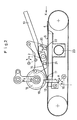
- the laminating station shown in FIG. 1 has a removable feed table 1, on the horizontal part of which a stack of sheets 2 is arranged. Below this stack of sheets 2 there is a conveying device 3, the conveying direction of which is denoted by X and on which the generally stronger sheets 4 are conveyed, which have been provided with the thinnest possible application of adhesive on their upper side in a gluing unit, not shown.
- the glued sheet 4 has a leading edge 5.
- the leading edge of the upper sheet 2 is designated by the reference numeral 6.
- the glued sheet 4 passes over the sufficiently long conveyor track of the conveyor 3, which consists of endless conveyor belts, to a horizontal conveyor track 7, which has spaced and parallel belt-shaped conveyor belts 8 (FIG. 3).
- the space between these conveyor belts 8 is designated by the reference number 9 (FIG. 3).
- the lower sheets 4 reach the area of a side alignment device 11 of a sheet table 10, which consists of at least one stop rail protruding upwards from the conveyor track 7, which aligns the lower sheets 4 transversely.
- a side alignment device 11 of a sheet table 10 which consists of at least one stop rail protruding upwards from the conveyor track 7, which aligns the lower sheets 4 transversely.
- the lower sheets 4 hit with their leading edge 5 against a stop 12 which projects upwards from the conveyor track 7 and which can be moved back and forth by motor in the directions A and B, in such a way that it moves away from the conveyor track 7 can be.
- the conveying path of the separating wedge 15 runs up to approximately in the region of the stop 12 at the same acute angle as the conveying path 13. Only at a relatively short distance, and already below a clock roller 16, is the Conveyor path of the separating wedge 15 angled into the horizontal - at 17 - and preferably abuts with its front edge 18 (FIG. 2) against the stop surface 19 of the stop 12, so that the upper sheet 2 is underpinned into the plane of the stop surface 19 by the separating wedge 15 and is led.
- the separating wedge 15 has a guide part 20 (FIG. 2) which is arranged in a guided manner via guides 21 and 22 in the directions C and D, that is to say horizontally. In this way it is possible to cut the wedge 15 by a limited amount To move direction D away from the abutment surface 19, whereupon the leading edges 5 and 6 of the lower arch 4 and upper arch 2 can be brought onto one another in a register-appropriate manner. It can thus be clearly seen that even with unstable paper it is not possible to bend the upper sheet 2.
- the clock roller 16 is driven to move back and forth by motor in the direction E or F.
- the sheet 4 is held on the conveyor belts 8 by a vacuum applied to a suction box 23. This vacuum can take effect through the spaces 9 between the conveyor belts 8 against the underside of the sheet 4.
- the separating wedge 15 is moved away in the direction D. Simultaneously or a short time later, the clock roller 16 is driven in the direction E and presses the upper sheet 2 in a register-correct and flat manner against the lower sheet 4, whereupon sheets 2 and 4 are laminated together.
- the clock roller 16 is moved back in the direction F into its starting position (FIG. 2).
- the separating wedge 15 returns to its starting position shown in FIG. 2 by a movement in the direction C.
- the stop 12 swings back in the direction A into its stop position, which can also be seen in FIG. 2, whereupon the work cycle is repeated.
Landscapes
- Physics & Mathematics (AREA)
- Fluid Mechanics (AREA)
- Registering Or Overturning Sheets (AREA)
- Folding Of Thin Sheet-Like Materials, Special Discharging Devices, And Others (AREA)
- Paper (AREA)
- Delivering By Means Of Belts And Rollers (AREA)
Priority Applications (1)
| Application Number | Priority Date | Filing Date | Title |
|---|---|---|---|
| AT84111317T ATE35795T1 (de) | 1984-09-22 | 1984-09-22 | Kaschierstation. |
Applications Claiming Priority (1)
| Application Number | Priority Date | Filing Date | Title |
|---|---|---|---|
| DE3315815A DE3315815C1 (de) | 1983-04-30 | 1983-04-30 | Verfahren und Vorrichtung zum Kaschieren von Bogen auf Bogen |
Publications (3)
| Publication Number | Publication Date |
|---|---|
| EP0175795A2 true EP0175795A2 (fr) | 1986-04-02 |
| EP0175795A3 EP0175795A3 (en) | 1987-08-19 |
| EP0175795B1 EP0175795B1 (fr) | 1988-07-20 |
Family
ID=6197846
Family Applications (1)
| Application Number | Title | Priority Date | Filing Date |
|---|---|---|---|
| EP84111317A Expired EP0175795B1 (fr) | 1983-04-30 | 1984-09-22 | Dispositif de laminage |
Country Status (4)
| Country | Link |
|---|---|
| US (1) | US4624719A (fr) |
| EP (1) | EP0175795B1 (fr) |
| JP (1) | JPS6034694A (fr) |
| DE (1) | DE3315815C1 (fr) |
Cited By (1)
| Publication number | Priority date | Publication date | Assignee | Title |
|---|---|---|---|---|
| EP0544977A1 (fr) * | 1991-12-03 | 1993-06-09 | Hakuto Co., Ltd. | Dispositif et procédé pour la lamination d'un film sur un substrat |
Families Citing this family (7)
| Publication number | Priority date | Publication date | Assignee | Title |
|---|---|---|---|---|
| DE3315815C1 (de) * | 1983-04-30 | 1984-11-08 | Tünkers Maschinenbau GmbH, 4030 Ratingen | Verfahren und Vorrichtung zum Kaschieren von Bogen auf Bogen |
| EP0603502B1 (fr) * | 1992-12-09 | 1996-09-18 | Kolbus GmbH & Co. KG | Machine à fabriquer des couvertures de livres |
| US5522157A (en) * | 1994-10-11 | 1996-06-04 | Eastman Kodak Company | Apparatus and method for drying stacks of sheet material |
| ES2141413T3 (es) * | 1996-04-23 | 2000-03-16 | Tuenkers Maschinenbau Gmbh | Procedimiento para forrar por ambas caras hojas de soporte con una hoja de recubrimiento por cada cara, e instalacion para realizar el procedimiento. |
| JP2007148539A (ja) * | 2005-11-24 | 2007-06-14 | Sankosha:Kk | 工事用簡易交通信号制御機 |
| DE102007034106A1 (de) | 2007-07-21 | 2009-01-22 | Tünkers Maschinenbau Gmbh | Verfahren zum beidseitigen Kaschieren eines Trägerbogens mit je einem Deckbogen im Durchlaufverfahren und Einrichtung zum Durchführen dieses Verfahrens |
| DE102007063164A1 (de) * | 2007-12-19 | 2009-08-27 | Wilhelm Bahmüller, Maschinenbau Präzisionswerkzeuge GmbH | Vorrichtung zur Zusammenführung mehrerer Kartons |
Family Cites Families (11)
| Publication number | Priority date | Publication date | Assignee | Title |
|---|---|---|---|---|
| US1669488A (en) * | 1926-01-16 | 1928-05-15 | Cross Ratcliff Lining And Moun | Machine for affixing sheets of paper or the like to boards, cards, or like mounts |
| US2725155A (en) * | 1951-07-19 | 1955-11-29 | Eastman Kodak Co | Semi-automatic readymount machine |
| DE1511291A1 (de) * | 1966-03-26 | 1969-06-19 | Prakma Maschinenfabrik Gmbh | Verfahren und Vorrichtung zum Kaschieren von Bogen auf Bogen |
| US3567047A (en) * | 1969-01-22 | 1971-03-02 | Simpson Timber Co | Stacking apparatus for wood veneer and other sheet material |
| DE1912150B2 (de) * | 1969-03-11 | 1977-02-17 | Karma Maschinen AG, Walchwill, Zug (Schweiz) | Verfahren und bogenkaschiermaschine zum zufuehren der kaschiersaetze zur presswalze |
| US3816866A (en) * | 1973-05-07 | 1974-06-18 | Harris Intertype Corp | Apparatus for making books |
| US3970506A (en) * | 1974-07-23 | 1976-07-20 | Bunker Ramo Corporation | Magnetic patch arrangement apparatus |
| US4025380A (en) * | 1975-07-24 | 1977-05-24 | International Business Machines Corporation | Variable resist laminator |
| US4189271A (en) * | 1977-04-27 | 1980-02-19 | Meinan Machinery Works, Inc. | Apparatus for piling veneer sheets |
| SE433926B (sv) * | 1981-05-04 | 1984-06-25 | Elvsborg Pack Ab | Maskin for kaschering av tva eller flera ark till ett flerskiktsark |
| DE3315815C1 (de) * | 1983-04-30 | 1984-11-08 | Tünkers Maschinenbau GmbH, 4030 Ratingen | Verfahren und Vorrichtung zum Kaschieren von Bogen auf Bogen |
-
1983
- 1983-04-30 DE DE3315815A patent/DE3315815C1/de not_active Expired
-
1984
- 1984-04-27 JP JP59084246A patent/JPS6034694A/ja active Pending
- 1984-09-22 EP EP84111317A patent/EP0175795B1/fr not_active Expired
- 1984-09-24 US US06/653,911 patent/US4624719A/en not_active Expired - Lifetime
Cited By (1)
| Publication number | Priority date | Publication date | Assignee | Title |
|---|---|---|---|---|
| EP0544977A1 (fr) * | 1991-12-03 | 1993-06-09 | Hakuto Co., Ltd. | Dispositif et procédé pour la lamination d'un film sur un substrat |
Also Published As
| Publication number | Publication date |
|---|---|
| DE3315815C1 (de) | 1984-11-08 |
| JPS6034694A (ja) | 1985-02-22 |
| EP0175795B1 (fr) | 1988-07-20 |
| EP0175795A3 (en) | 1987-08-19 |
| US4624719A (en) | 1986-11-25 |
Similar Documents
| Publication | Publication Date | Title |
|---|---|---|
| EP0109041A1 (fr) | Procédé et dispositif de reliure de livres | |
| CH460818A (de) | Verfahren zum Auffächern der Blätter eines Stapels senkrecht übereinander liegender Blätter und Vorrichtung zur Durchführung des Verfahrens | |
| DE3221151A1 (de) | Einrichtung zum seitlichen beschneiden von papierbogen | |
| EP0275521B1 (fr) | Dispositif pour coller les gardes d'une machine à relier | |
| EP0175795B1 (fr) | Dispositif de laminage | |
| DE2627810C3 (de) | Vorrichtung zum Vereinzeln, Transportieren und Ablegen von Vergütungsbögen im Zuge der Herstellung von vergüteten Spanplatten, Faserplatten o.dgl | |
| DE4013116A1 (de) | Verfahren zum stapeln flacher zuschnitte aus karton oder dergleichen und entsprechende stapeleinrichtung | |
| DE3702155C2 (fr) | ||
| DE69713371T2 (de) | Vorrichtung zum miteinanderverbinden von flachen gegenständen | |
| EP1886833A1 (fr) | Procédé et dispositif de fabrication d'un objet imprimé relié par adhésif à partir de plusieurs produits imprimés | |
| DE3510147A1 (de) | Vorrichtung zum beleimen streifenfoermiger flaechen zweier werkstuecke | |
| DE1900228A1 (de) | Vorrichtung zum kontinuierlichen stirnseitigen Profilieren und Leimauftragen stirnseitig miteinander zu verbindender Hoelzer | |
| DE3410029C1 (de) | Ausrichtetisch | |
| DE4236033A1 (de) | Umschlaganlegevorrichtung für eine Buchbindemaschine | |
| EP0128352B1 (fr) | Dispositif de transport et d'empilage de feuilles | |
| DE2749095A1 (de) | Vorrichtung zum oeffnen von druckprodukten | |
| DE2800383C2 (fr) | ||
| DE4432124C2 (de) | Vorrichtung zum Vereinzeln von Zeitschriften-Remittenden von der Unterseite eines Stapels | |
| DE3527660A1 (de) | Verfahren und vorrichtung zur herstellung mehrseitiger, gefalzter und verklebter blattlagen | |
| DE2731632A1 (de) | Vorrichtung zur einzelblattentnahme von der unterseite eines blattstapels, insbesondere eines zuschnittstapels fuer die tabakverarbeitende industrie | |
| DE8312820U1 (de) | Kaschiervorrichtung | |
| WO2005018923A1 (fr) | Dispositif de pressage pour sacs dont le fond est colle | |
| DE3118308A1 (de) | Vorrichtung zum vereinzeln eines stapels gefalteter oder gebundener, mehrblaettriger druckprodukte | |
| CH693329A5 (de) | Vorrichtung zum Auftrageneines Klebstoffstreifens auf einen gefalztenVorsatzbogen. | |
| DE2230631C3 (de) | Verfahren zum Herstellen quaderförmiger Schachteln |
Legal Events
| Date | Code | Title | Description |
|---|---|---|---|
| PUAI | Public reference made under article 153(3) epc to a published international application that has entered the european phase |
Free format text: ORIGINAL CODE: 0009012 |
|
| 17P | Request for examination filed |
Effective date: 19841018 |
|
| AK | Designated contracting states |
Kind code of ref document: A2 Designated state(s): AT CH FR GB IT LI NL |
|
| PUAL | Search report despatched |
Free format text: ORIGINAL CODE: 0009013 |
|
| AK | Designated contracting states |
Kind code of ref document: A3 Designated state(s): AT CH FR GB IT LI NL |
|
| 17Q | First examination report despatched |
Effective date: 19871016 |
|
| ITF | It: translation for a ep patent filed | ||
| GRAA | (expected) grant |
Free format text: ORIGINAL CODE: 0009210 |
|
| AK | Designated contracting states |
Kind code of ref document: B1 Designated state(s): AT CH FR GB IT LI NL |
|
| REF | Corresponds to: |
Ref document number: 35795 Country of ref document: AT Date of ref document: 19880815 Kind code of ref document: T |
|
| ET | Fr: translation filed | ||
| GBT | Gb: translation of ep patent filed (gb section 77(6)(a)/1977) | ||
| PLBE | No opposition filed within time limit |
Free format text: ORIGINAL CODE: 0009261 |
|
| STAA | Information on the status of an ep patent application or granted ep patent |
Free format text: STATUS: NO OPPOSITION FILED WITHIN TIME LIMIT |
|
| 26N | No opposition filed | ||
| ITTA | It: last paid annual fee | ||
| REG | Reference to a national code |
Ref country code: GB Ref legal event code: IF02 |
|
| PGFP | Annual fee paid to national office [announced via postgrant information from national office to epo] |
Ref country code: FR Payment date: 20030909 Year of fee payment: 20 |
|
| PGFP | Annual fee paid to national office [announced via postgrant information from national office to epo] |
Ref country code: AT Payment date: 20030911 Year of fee payment: 20 |
|
| PGFP | Annual fee paid to national office [announced via postgrant information from national office to epo] |
Ref country code: GB Payment date: 20030917 Year of fee payment: 20 |
|
| PGFP | Annual fee paid to national office [announced via postgrant information from national office to epo] |
Ref country code: NL Payment date: 20030922 Year of fee payment: 20 |
|
| PGFP | Annual fee paid to national office [announced via postgrant information from national office to epo] |
Ref country code: CH Payment date: 20030930 Year of fee payment: 20 |
|
| PG25 | Lapsed in a contracting state [announced via postgrant information from national office to epo] |
Ref country code: LI Free format text: LAPSE BECAUSE OF EXPIRATION OF PROTECTION Effective date: 20040921 Ref country code: GB Free format text: LAPSE BECAUSE OF EXPIRATION OF PROTECTION Effective date: 20040921 Ref country code: CH Free format text: LAPSE BECAUSE OF EXPIRATION OF PROTECTION Effective date: 20040921 |
|
| PG25 | Lapsed in a contracting state [announced via postgrant information from national office to epo] |
Ref country code: NL Free format text: LAPSE BECAUSE OF EXPIRATION OF PROTECTION Effective date: 20040922 Ref country code: AT Free format text: LAPSE BECAUSE OF EXPIRATION OF PROTECTION Effective date: 20040922 |
|
| REG | Reference to a national code |
Ref country code: GB Ref legal event code: PE20 |
|
| REG | Reference to a national code |
Ref country code: CH Ref legal event code: PL |
|
| NLV7 | Nl: ceased due to reaching the maximum lifetime of a patent |
Effective date: 20040922 |