EP0175875A1 - Brûleur à huile ou à gaz pour la génération de gaz à chaud - Google Patents
Brûleur à huile ou à gaz pour la génération de gaz à chaud Download PDFInfo
- Publication number
- EP0175875A1 EP0175875A1 EP85109292A EP85109292A EP0175875A1 EP 0175875 A1 EP0175875 A1 EP 0175875A1 EP 85109292 A EP85109292 A EP 85109292A EP 85109292 A EP85109292 A EP 85109292A EP 0175875 A1 EP0175875 A1 EP 0175875A1
- Authority
- EP
- European Patent Office
- Prior art keywords
- mixing tube
- openings
- burner according
- nozzle
- diameter
- Prior art date
- Legal status (The legal status is an assumption and is not a legal conclusion. Google has not performed a legal analysis and makes no representation as to the accuracy of the status listed.)
- Granted
Links
Images




Classifications
-
- F—MECHANICAL ENGINEERING; LIGHTING; HEATING; WEAPONS; BLASTING
- F23—COMBUSTION APPARATUS; COMBUSTION PROCESSES
- F23D—BURNERS
- F23D11/00—Burners using a direct spraying action of liquid droplets or vaporised liquid into the combustion space
- F23D11/36—Details
- F23D11/40—Mixing tubes; Burner heads
Definitions
- the invention relates to a burner for generating hot gas with a nozzle from which a fuel jet enters a mixing tube, with a diaphragm surrounding the outlet of the nozzle, which burner housing into an upstream prechamber accommodating the nozzle and a downstream combustion chamber accommodating the mixing tube divided, with a central passage in the orifice for the passage of the fuel jet emerging from the nozzle and with a number of openings in the orifice surrounding the passage through which combustion air enters the mixing tube from the prechamber, the openings being located within a surface , which results from the projection of the clear mixing tube cross-sectional area onto the screen.
- combustion air is supplied to the fuel, which is fed centrally via a nozzle, through openings are arranged in an aperture surrounding the nozzle.
- the combustion air and the fuel are mixed downstream of the nozzle in a mixing chamber which is arranged in a mixing tube in the known burners.
- a flame front forms during operation, from which hot gases outside the mixing tube flow back to a recirculation opening at the upstream end of the mixing tube.
- This object is achieved according to the invention in a burner of the type described in the introduction in that the distance between the edges of adjacent openings is at least 50% of the opening diameter and / or in that the openings in the diaphragm in the flow direction are preceded by at least one air duct which is at least in the radial direction outer edges of the openings smoothly merging into the openings.
- the openings surrounding the nozzle in the diaphragm had been arranged so that the edges. Adjacent openings are close together in order to achieve the largest possible passage area for the combustion air, it has been found that an increase in this distance leads to a reduction in noise. Accordingly, the distance between adjacent openings in the circumferential direction of a pitch circle should be at least 50% of the opening diameter. Such an increase in the distance between the combustion air openings leads to a reduction in the noise level of a few dB ( A ).
- An air duct upstream of the openings directs the combustion air approximately parallel before it passes through the openings and before it enters the mixing chamber, so that less disturbed flow can be achieved. This prevents turbulence from being carried into the mixing chamber which would otherwise continue in the flame and in the recirculation flow and would lead to increased combustion noises.
- An arrangement has proven to be particularly advantageous in which the longitudinal axes of the openings are inclined to converge in the flow direction with respect to the longitudinal axis of the mixing tube, preferably with an angle of inclination between 3 ° and 6 °.
- This can be achieved by arranging the openings in the diaphragm itself or by deforming the diaphragm in such a way that the longitudinal axes of the openings are inclined with respect to the longitudinal axis of the mixing tube.
- the channel is formed by a tube piece surrounding the nozzle at a concentric distance.
- a common air supply channel is thus assigned to all openings, which is formed by the annular gap between the inner wall of the pipe socket and the nozzle.
- the annular gap can be arranged along a cone narrowing in the direction of flow. This additionally achieves an effect which reduces the turbulence in the air flow, which is particularly advantageous in particular in combination with an opening with an inclined longitudinal axis.
- the noise-reducing effect of the pipe section is particularly favorable if its length is between 10 and 120% of its inside diameter in the transition area to the openings; this length is preferably between 20 and 70% of the inside diameter, and it is very particularly favorable if this length is between 30 and 50% of the inside diameter of the pipe piece.
- each opening is assigned its own air duct, which merges smoothly into the opening. It can also be provided here that the air guide channels narrow conically in the flow direction.
- the air ducts can be arranged on a cylindrical surface concentrically surrounding the nozzle, in a modified embodiment they are arranged on a conical outer surface concentrically surrounding the nozzle. It is advantageous if the longitudinal axis of the channels is inclined between 3 ° and 6 ° with respect to the longitudinal axis of the mixing tube, since then optimal mixing takes place in the interior of the mixing tube without the undesirable turbulence occurring.
- the air duct can be worked into a common guide body concentrically surrounding the nozzle.
- the length of these air supply ducts corresponds to 0.5 to 4 times the radial distance of the openings from the longitudinal axis of the nozzle, preferably to 2 to 3 times the radial distance of these openings from the longitudinal axis of the nozzle.
- annular gap concentrically surrounding the nozzle which is immediately adjacent, is arranged in the diaphragm and is connected to the antechamber. Combustion air can also flow into the mixing chamber very close to the longitudinal axis of the nozzle through this annular gap which immediately surrounds the passage opening of the nozzle through the orifice.
- the openings in the diaphragm can have a circular cross section, but it is also possible to use other cross sections, for example the openings can have the shape of ring sections.
- the adjacent openings can be on a common circle around the nozzle axis, but they can also be offset from one another in the radial direction, so that, for example, openings are arranged on two concentrically arranged partial circles which are offset from one another.
- the distance between the edges of adjacent openings is more than 50% of the opening diameter, in particular more than 100%.
- the mixing tube has a larger diameter at its upstream end than at its downstream end.
- the mixing tube can narrow in steps or conically.
- the upstream end of the mixing tube has an inner diameter which is larger than the diameter of a circumferential circle lying on the outer sides of the openings; in a modified embodiment, the inner diameter can also be chosen so that it is equal to the diameter of this circumferential circle.
- recirculation openings are provided in the jacket of the upstream end of the mixing tube which adjoins the orifice and are arranged at a distance from the orifice so that there is a closed piece of pipe between the orifice and the recirculation openings located.
- the length of the pipe section preferably corresponds to approximately 1/4 of the mixing pipe diameter.
- a further pipe section adjoins the mixing tube downstream, the diameter of which is at most as large as that of the downstream end of the mixing tube.
- This piece of pipe is advantageously at a distance from the downstream end of the mixing tube which is between 1/10 and 1/4 of the diameter of the mixing tube. It is advantageous if the length of this pipe piece is between 1/2 and 1 diameter of the mixing tube, preferably 2/3 of this diameter. Also by this measure The overall sound level is reduced, namely by pressing a core flow again through a constriction after leaving the large mixing tube part, with the aim of dampening the vortex formation occurring at the inner mixing cone of the flow.
- each of the measures relating to the supply of the combustion air into the mixing tube also contributes to a desired reduction in noise on its own.
- Each of these measures can be combined to further reduce the noise with each of the features relating to the design of the mixing tube. Protection is therefore expressly claimed for the combination of all of these features or some of these features as well as for the individual features relating to the combustion air supply to the mixing tube.
- the invention relates to a wide variety of oil or gas burners and is discussed below using the example of a so-called blue burner, ie a burner in which oil is completely burned with a blue flame.
- a so-called blue burner ie a burner in which oil is completely burned with a blue flame.
- the Erfin but is not limited to such blue burners, for example, the desired noise reduction can be achieved with the described design measures even with warming-up burners and yellow burners.
- the burner shown in FIGS. 1 and 2 comprises a cylindrical burner housing 1, which is subdivided into an upstream antechamber 3 and a downstream combustion chamber 4 by a wall, which is referred to below as an orifice 2.
- the orifice 2 has a central passage 5 , in which a nozzle 6 is inserted, which is connected to a fuel supply line 7.
- the longitudinal axis of the nozzle 6 coincides with the longitudinal axis of the burner housing.
- a cylindrical mixing tube 8 Downstream of the orifice 2 is connected to this a cylindrical mixing tube 8 which, via circumferential slots 9 immediately after the orifice 2, forms a connection between its interior 10 forming the mixing space and an annular space 11 serving as a recirculation space, which surrounds the mixing tube 8 concentrically.
- An ignition device 12 is led from the prechamber through the diaphragm 2 and ends at the outlet end of the mixing tube 8, so that ignition can take place in this area.
- a measuring probe 13 is inserted from the antechamber through the orifice 2 into the combustion chamber 4.
- a number of openings 14 are arranged, each with a circular cross section, which ver create bond between the prechamber 3 and the interior 10 surrounded by the mixing tube 8 in the combustion chamber 4.
- the nozzle 6 is surrounded at a distance by a cylindrical pipe section 15 which extends up to the diaphragm 2.
- the inside diameter of this pipe section 15 is selected such that the inner wall of the pipe section 15 merges smoothly into the openings 14 in the region of the outer edges of the openings 14, as is clear from FIG. 2.
- the radius of the circle on which the openings 14 lie lies between the outer radius of the nozzle 6 and the radius of the inner wall of the pipe section 15, so that the openings 14 with the inner region of their edge are the envelope of the nozzle 6 touch, with the outside area the inner wall of the pipe section 15.
- the number of openings 14 along the circle surrounding the nozzle is selected such that webs 16 remain between the openings, the width of which is at least 50% of the diameter of the openings 14. It is particularly advantageous if the inside diameter of the pipe section 15 is slightly smaller than the inside diameter of the mixing pipe 8. This allows a maximum distance of adjacent openings in the circumferential direction to be achieved with a given cross-sectional area of the openings 14, this maximum distance leading to the best possible noise reduction. If the inside diameter of the pipe section is increased beyond the inside diameter of the mixing tube, there is again an increase in noise despite the even greater distances between adjacent bores.
- fuel for example gas or oil
- the nozzle can in use; of oil as an atomizer nozzle.
- Combustion air is introduced through the openings 14 into the interior 10 of the mixing tube 8, so that fuel and combustion air mix intimately with one another in the interior 10.
- this mixture is ignited and burns in a flame front which is located approximately in the area of the outlet-side end of the mixing tube in accordance with the respective flow rate.
- the combustion air is passed through the pipe section 15 through an annular channel 17 surrounding the nozzle 6 before the combustion air can enter the interior 10 of the mixing pipe 8 through the openings 14.
- the air flow is calmed, so that the air passes through the openings 14 largely without turbulence.
- the turbulence is also reduced in the mixing tube 8 and in the combustion area compared to a construction in which the air enters the mixing tube 8 directly from the prechamber without a guide channel upstream of the openings 14. Due to the low turbulence, there is a significant reduction in noise during the burning process itself.
- the tube piece 15 is cylindrical in the embodiment shown in Figure 1 (solid lines).
- the pipe section 15 has the shape of a truncated cone, and a parallel inner wall forms with the pipe section an annular gap 17 running along a truncated cone jacket.
- Such an arrangement is shown in Figure 1 with dash-dotted lines. This arrangement also contributes to a calming of the air flow.
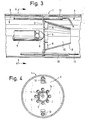
- FIGS. 3 and 4 A burner of similar construction is shown in FIGS. 3 and 4, parts corresponding to one another have the same reference numerals.
- the mixing tube 8 is frustoconical, the inlet end having an outer diameter which is substantially larger than the diameter of the circle on which the openings 14 are arranged. It has been found that this conical narrowing of the mixing tube leads to an additional reduction in noise during the burning process.
- an air supply duct comparable to the pipe section 15 is missing. Instead, the openings 14 are chamfered on their side facing the prechamber 3. These chamfers, which are incorporated directly into the diaphragm 2, also form air guide channels which lead to a substantial calming of the combustion air flowing into the mixing tube and thus to a reduction in noise. These chamfers are effective in their own right in reducing noise, but their effect can be combined particularly advantageously with other upstream air supply ducts, for example with the pipe section 15 of the exemplary embodiment in FIGS. 1 and 2.
- the nozzle 6 is surrounded by a guide body 18, in which axially parallel channels 19 are incorporated, in such a way that each opening 14 is assigned its own channel 19.
- the channels 19 enter the respective opening 14 smoothly.
- the channels 19 have the same cross section over their entire length, but it can be provided that the channels 19 narrow in the direction of flow.
- the channels 19 can run axially parallel in the guide body, as shown in solid lines in FIG. 5, but they can also be arranged on a conical jacket, as is indicated by dash-dotted lines in FIG. It is advantageous if the inclination of the channels 19 with respect to the longitudinal axis of the nozzle is between 3 ° and 6 °. It has been found that optimal noise reduction can be achieved with such an arrangement. In this case, too, the channels themselves can still narrow in the direction of flow. It is important in this context that in all cases the channels 19 pass into the openings 14 smoothly, so that no turbulence can occur in this transition area.
- the mixing tube 8 is extended compared to the exemplary embodiments in FIGS. 1 to 4, so that the length is approximately up to three times as large as the inside diameter of the mixing tube inlet.
- This extension of the mixing tube also contributes to an additional reduction in noise.
- the extended mixing tube has an ignition in one of the orifices To allow 2 near area, the mixing tube points in this.
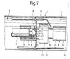
- FIG. 7 A further preferred exemplary embodiment of a burner is shown in FIG. 7, in which corresponding parts are again identified by the same reference numerals.
- annular space 21 which surrounds the nozzle 6 in the region of the opening 5 and which opens into an annular gap 22 surrounding the opening 5 is incorporated into the guide body 18.
- the annular gap 22 can be formed by the opening 5 itself, which then has a diameter which is somewhat larger than the diameter of the nozzle 6 in this area.
- the annular space 21 communicates with the prechamber 3 via channels 23, which run essentially radially in the guide body 18, so that combustion air can enter the interior not only via the channels 19 and the openings 14, but also for the channels 23, the annular space 21 and the annular gap 22. Since this combustion air occurs in the immediate vicinity of the fuel entering the interior, a particularly effective mixing can take place here, the introduction of turbulence into the interior by the combustion air being largely avoided. This measure also serves to reduce noise.
- the mixing tube 8 is extended and has jacket openings 20.
- the part 24 of the mixing tube located upstream of the jacket opening 20 has a larger diameter than the part 25 located downstream of the jacket opening 20.
- the diameter of the part 24 is considerably larger than the diameter of the circle on which the openings 14 lie.
- the axes of the openings 14 run parallel to the longitudinal axis of the mixing tube 8.
- these openings in the diaphragm in such a way that their longitudinal axes are convergingly inclined in the flow direction with respect to the longitudinal axis of the mixing tube, for example with an inclination angle between 3 ° and 6 °.
- This inclination can be generated by appropriately incorporating the openings into the orifice or by deforming the orifice in the region of the openings 14. It has been found that this slight inclination of the longitudinal axis of the opening and thus of the direction of flow inclined in the direction of the longitudinal axis of the mixing tube Incoming combustion air while improving the mixing results in an additional reduction in noise.
- the combustion air can be introduced into the mixing chamber largely without turbulence, so that this results in a considerable reduction tion of noise can be achieved.
- the overall sound level can be reduced, for example, by 8 to 10 dB (A) of the absolute value if you compare the noise level with that of a burner in which the combustion air enters the mixing room directly through the openings in the panel without suitable protective measures.
- the exemplary embodiment in FIG. 8 is constructed in the region of the prechamber and the air inlet ducts like the exemplary embodiment in FIG. 3, so that reference is made to this exemplary embodiment.
- the burner differs from the exemplary embodiment in FIG. 5, to the explanatory description of which reference is made only in that the circumferential slots 9 are at a distance from the orifice 2, so that a between the orifice 2 and the circumferential slots 9 Pipe piece 30 is formed with a closed outer surface.
- This pipe section 30 has a length which corresponds to approximately 1/4 of the mixing pipe diameter. It has been found that this has an effect on the formation of vortices in the mixing tube which reduces the overall sound level.
- the burner in the region of the prechamber is designed in the same way as in the exemplary embodiment in FIG. 8.
- the structure differs from the exemplary embodiment in FIG. 7 only in that the inner diameter of the upstream part 24 of the mixing tube 8 the diameter of the circumference corresponds to the circle, which surrounds the openings 14 on the outside.
- the inside diameter of the downstream part 25 is correspondingly smaller. This version also helps to reduce the overall sound level.
- FIG. 10 largely corresponds to that of FIG. 8. It differs from this only in that the mixing tube 8 is followed by a further, coaxially arranged pipe section 40 which is at a distance from the end of the mixing tube which is between 1/10 and 1 / 4 of the mixing tube diameter.
- the length of the pipe section 40 is between 1/2 and 1 mixing pipe diameter, preferably 2/3 of this diameter.
- the inside diameter of the pipe section 40 can be equal to the inside diameter of the mixing pipe 8 at its outlet, but the inside diameter of the pipe section 40 is preferably smaller, as is shown in the exemplary embodiment in FIG. 10.
- mixing tube can also be combined with one another in another way, for example a mixing tube can have circumferential slots 9 offset downstream and a pipe section 40 attached downstream, the mixing tube can also narrow in the flow direction.
- the different mixing tube configurations can be combined in any way with the different configurations in the area of the antechamber, which are discussed in the context of this application.
Landscapes
- Engineering & Computer Science (AREA)
- Chemical & Material Sciences (AREA)
- Combustion & Propulsion (AREA)
- Mechanical Engineering (AREA)
- General Engineering & Computer Science (AREA)
- Gas Burners (AREA)
- Pre-Mixing And Non-Premixing Gas Burner (AREA)
- Feeding, Discharge, Calcimining, Fusing, And Gas-Generation Devices (AREA)
- Heterocyclic Carbon Compounds Containing A Hetero Ring Having Nitrogen And Oxygen As The Only Ring Hetero Atoms (AREA)
- Nitrogen Condensed Heterocyclic Rings (AREA)
- Pressure-Spray And Ultrasonic-Wave- Spray Burners (AREA)
- Spray-Type Burners (AREA)
- Treating Waste Gases (AREA)
- Feeding And Controlling Fuel (AREA)
Priority Applications (1)
| Application Number | Priority Date | Filing Date | Title |
|---|---|---|---|
| AT85109292T ATE34447T1 (de) | 1984-08-16 | 1985-07-24 | Oel- oder gasbrenner zur heissgaserzeugung. |
Applications Claiming Priority (2)
| Application Number | Priority Date | Filing Date | Title |
|---|---|---|---|
| DE19843430010 DE3430010A1 (de) | 1984-08-16 | 1984-08-16 | Brenner zur heissgaserzeugung |
| DE3430010 | 1984-08-16 |
Publications (2)
| Publication Number | Publication Date |
|---|---|
| EP0175875A1 true EP0175875A1 (fr) | 1986-04-02 |
| EP0175875B1 EP0175875B1 (fr) | 1988-05-18 |
Family
ID=6243088
Family Applications (1)
| Application Number | Title | Priority Date | Filing Date |
|---|---|---|---|
| EP85109292A Expired EP0175875B1 (fr) | 1984-08-16 | 1985-07-24 | Brûleur à huile ou à gaz pour la génération de gaz à chaud |
Country Status (9)
| Country | Link |
|---|---|
| US (1) | US4629414A (fr) |
| EP (1) | EP0175875B1 (fr) |
| JP (1) | JPS61125511A (fr) |
| AT (1) | ATE34447T1 (fr) |
| CA (1) | CA1259557A (fr) |
| DE (2) | DE3430010A1 (fr) |
| DK (1) | DK160642C (fr) |
| FI (1) | FI86106C (fr) |
| NO (1) | NO160314C (fr) |
Cited By (2)
| Publication number | Priority date | Publication date | Assignee | Title |
|---|---|---|---|---|
| WO1988008503A1 (fr) * | 1987-04-30 | 1988-11-03 | May Michael G | Procede et agencement de combustion de combustible |
| WO1993019326A1 (fr) * | 1992-03-21 | 1993-09-30 | Deutsche Forschungsanstalt Für Luft- Und Raumfahr T E.V. | Bruleur exempt de depots |
Families Citing this family (18)
| Publication number | Priority date | Publication date | Assignee | Title |
|---|---|---|---|---|
| US4673350A (en) * | 1986-08-26 | 1987-06-16 | Eclipse, Inc. | Burner assembly for radiant tube heating system |
| US4705022A (en) * | 1986-09-25 | 1987-11-10 | Eclipse, Inc. | Recuperative radiant tube heating system |
| DE3801681C1 (en) * | 1988-01-21 | 1989-05-18 | Deutsche Forschungs- Und Versuchsanstalt Fuer Luft- Und Raumfahrt Ev, 5300 Bonn, De | Method for burning gaseous or liquid fuel and burner for carrying out this method |
| DE3801679C1 (en) * | 1988-01-21 | 1989-05-11 | Deutsche Forschungs- Und Versuchsanstalt Fuer Luft- Und Raumfahrt Ev, 5300 Bonn, De | Burner for gaseous or liquid fuel |
| DE4201060C2 (de) * | 1992-01-17 | 1994-07-14 | Man B & W Diesel Ag | Brenner für vergasten flüssigen Brennstoff |
| DE4201061C2 (de) * | 1992-01-17 | 1994-06-23 | Man B & W Diesel Ag | Brenner für vergasten flüssigen Brennstoff |
| DE4201059C2 (de) * | 1992-01-17 | 1994-06-09 | Man B & W Diesel Ag | Flammrohr für einen Brenner für vergasten flüssigen Brennstoff |
| ATE142324T1 (de) * | 1992-02-28 | 1996-09-15 | Fuellemann Patent Ag | Brenner, insbesondere oelbrenner oder kombinierter oel/gas-brenner |
| US5393224A (en) * | 1993-12-02 | 1995-02-28 | American Standard Inc. | Ignitor assembly for power burner furnace |
| US5927963A (en) * | 1997-07-15 | 1999-07-27 | Gas Electronics, Inc. | Pilot assembly and control system |
| DE10004475C2 (de) * | 2000-02-02 | 2002-08-22 | Bosch Gmbh Robert | Drallbrenner mit einem Drallkörper als Brennerelement in einer Brennkammer |
| EP1279895A1 (fr) * | 2001-07-25 | 2003-01-29 | Compagnie Europeenne de Bruleurs | Tête de combustion d'un brûleur comprenant une zone de pré-vaporisation du combustible liquide |
| US6743010B2 (en) | 2002-02-19 | 2004-06-01 | Gas Electronics, Inc. | Relighter control system |
| CA2493891A1 (fr) * | 2002-07-19 | 2004-01-29 | Shell Internationale Research Maatschappij B.V. | Utilisation d'un bruleur a gaz a flamme blanche |
| JP2005533234A (ja) * | 2002-07-19 | 2005-11-04 | シエル・インターナシヨネイル・リサーチ・マーチヤツピイ・ベー・ウイ | 青炎式バーナーの使用 |
| DE502006005173D1 (de) * | 2006-02-22 | 2009-12-03 | Tempratec Ltd | Vorrichtung und Verfahren zum Verbrennen eines Brennstoffes |
| JP4739275B2 (ja) * | 2006-08-11 | 2011-08-03 | Jx日鉱日石エネルギー株式会社 | バーナ |
| DE102016113222A1 (de) * | 2016-07-18 | 2018-01-18 | Webasto SE | Brenner und Fahrzeugheizgerät |
Citations (3)
| Publication number | Priority date | Publication date | Assignee | Title |
|---|---|---|---|---|
| DE2712564A1 (de) * | 1977-03-22 | 1978-10-05 | Weishaupt Max Gmbh | Brenner fuer fluessige brennstoffe |
| DE3109988A1 (de) * | 1981-03-14 | 1982-12-02 | Klaus 2000 Hamburg Eckloff | Vergaser-oelbrenner |
| EP0115858A1 (fr) * | 1983-02-08 | 1984-08-15 | M.A.N. MASCHINENFABRIK AUGSBURG-NÜRNBERG Aktiengesellschaft | Brûleur à monter dans les installations de chauffage et de production de vapeur |
Family Cites Families (12)
| Publication number | Priority date | Publication date | Assignee | Title |
|---|---|---|---|---|
| US2857961A (en) * | 1954-07-13 | 1958-10-28 | Brown Fintube Co | Oil burners |
| DE1401849B2 (de) * | 1960-08-01 | 1972-02-24 | Webasto-Werk GmbH, 8031 Stockdorf | Brenner fuer industrieoefen |
| US3609073A (en) * | 1968-02-26 | 1971-09-28 | Dickinson S Ltd | Oil burner apparatus |
| US3545902A (en) * | 1968-09-23 | 1970-12-08 | Frank W Bailey | Blue-flame gun burner process and apparatus for liquid hydrocarbon fuel |
| DE2545234C2 (de) * | 1975-10-09 | 1983-09-15 | Fa. J. Eberspächer, 7300 Esslingen | Mischeinrichtung für Brenner |
| DE2700671C2 (de) * | 1977-01-08 | 1988-07-28 | Deutsche Forschungs- und Versuchsanstalt für Luft- und Raumfahrt e.V., 5000 Köln | Blaubrennender Ölbrenner |
| US4364725A (en) * | 1977-01-08 | 1982-12-21 | Deutsche Forschungs- Und Versuchsanstalt Fur Luft- Und Raumfahrt E.V. | Blue-flame oil burner |
| DE2821932A1 (de) * | 1978-05-19 | 1979-11-22 | Karl Bodemer | Mischeinrichtung zur verbrennung von fluessigen kohlenwasserstoffen, insbesondere heizoel und dieseloel |
| DE2918416C2 (de) * | 1979-05-08 | 1985-05-15 | Deutsche Forschungs- und Versuchsanstalt für Luft- und Raumfahrt e.V., 5000 Köln | Vergasungsölbrenner |
| DE3035707A1 (de) * | 1980-09-22 | 1982-04-08 | Deutsche Forschungs- und Versuchsanstalt für Luft- und Raumfahrt e.V., 5000 Köln | Oel- und gasbrenner zum einbau in heizungs- und dampferzeugungskessel |
| JPS58200911A (ja) * | 1982-05-17 | 1983-11-22 | Inax Corp | 液体燃料の燃焼装置 |
| JPS6367086A (ja) * | 1986-09-08 | 1988-03-25 | Matsushita Electric Ind Co Ltd | 映像信号処理装置 |
-
1984
- 1984-08-16 DE DE19843430010 patent/DE3430010A1/de active Granted
-
1985
- 1985-07-24 DE DE8585109292T patent/DE3562819D1/de not_active Expired
- 1985-07-24 AT AT85109292T patent/ATE34447T1/de not_active IP Right Cessation
- 1985-07-24 EP EP85109292A patent/EP0175875B1/fr not_active Expired
- 1985-08-08 US US06/763,824 patent/US4629414A/en not_active Expired - Lifetime
- 1985-08-14 JP JP60177757A patent/JPS61125511A/ja active Granted
- 1985-08-15 FI FI853128A patent/FI86106C/fi not_active IP Right Cessation
- 1985-08-15 NO NO853217A patent/NO160314C/no unknown
- 1985-08-15 DK DK370785A patent/DK160642C/da not_active IP Right Cessation
- 1985-08-15 CA CA000488772A patent/CA1259557A/fr not_active Expired
Patent Citations (3)
| Publication number | Priority date | Publication date | Assignee | Title |
|---|---|---|---|---|
| DE2712564A1 (de) * | 1977-03-22 | 1978-10-05 | Weishaupt Max Gmbh | Brenner fuer fluessige brennstoffe |
| DE3109988A1 (de) * | 1981-03-14 | 1982-12-02 | Klaus 2000 Hamburg Eckloff | Vergaser-oelbrenner |
| EP0115858A1 (fr) * | 1983-02-08 | 1984-08-15 | M.A.N. MASCHINENFABRIK AUGSBURG-NÜRNBERG Aktiengesellschaft | Brûleur à monter dans les installations de chauffage et de production de vapeur |
Cited By (3)
| Publication number | Priority date | Publication date | Assignee | Title |
|---|---|---|---|---|
| WO1988008503A1 (fr) * | 1987-04-30 | 1988-11-03 | May Michael G | Procede et agencement de combustion de combustible |
| WO1993019326A1 (fr) * | 1992-03-21 | 1993-09-30 | Deutsche Forschungsanstalt Für Luft- Und Raumfahr T E.V. | Bruleur exempt de depots |
| US5433601A (en) * | 1992-03-21 | 1995-07-18 | Deutsche Forschungsanstalt Fuer Luft- Und Raumfahrt E.V. | Deposit-free burner |
Also Published As
| Publication number | Publication date |
|---|---|
| DK370785D0 (da) | 1985-08-15 |
| DE3430010A1 (de) | 1986-02-27 |
| CA1259557A (fr) | 1989-09-19 |
| JPS61125511A (ja) | 1986-06-13 |
| FI86106B (fi) | 1992-03-31 |
| EP0175875B1 (fr) | 1988-05-18 |
| NO853217L (no) | 1986-02-17 |
| US4629414A (en) | 1986-12-16 |
| DK160642C (da) | 1991-09-02 |
| NO160314C (no) | 1989-04-05 |
| DK160642B (da) | 1991-04-02 |
| FI86106C (fi) | 1992-07-10 |
| FI853128A0 (fi) | 1985-08-15 |
| DK370785A (da) | 1986-02-17 |
| FI853128L (fi) | 1986-02-17 |
| DE3430010C2 (fr) | 1987-11-12 |
| JPH0240924B2 (fr) | 1990-09-13 |
| DE3562819D1 (en) | 1988-06-23 |
| ATE34447T1 (de) | 1988-06-15 |
| NO160314B (no) | 1988-12-27 |
Similar Documents
| Publication | Publication Date | Title |
|---|---|---|
| EP0175875B1 (fr) | Brûleur à huile ou à gaz pour la génération de gaz à chaud | |
| EP0438682B1 (fr) | Système d'échappement avec filtre à particules et brûleur de régénération | |
| DE2143012C3 (de) | Brenneranordnung bei einer Gasturbinen-Brennkammer | |
| DE2131490C2 (de) | Brenner-Mischdüse | |
| DE3217674C2 (de) | Brennkammer für eine Gasturbine | |
| DE3842842A1 (de) | Atmosphaerischer brenner | |
| WO2006042796A2 (fr) | Bruleur pour turbine a gaz | |
| DE3321697A1 (de) | Sauerstoff-schneidbrenner | |
| DE3244854A1 (de) | Brenner | |
| DE1932881A1 (de) | Brennkammer | |
| DE2511500C2 (de) | Brenner zur Verbrennung von flüssigem Brennstoff | |
| DE4323300C2 (de) | Mischvorrichtung für einen Brenner | |
| DE2345838A1 (de) | Brenner | |
| DE69818909T2 (de) | Brennerkopf für Gasbrenner | |
| DE1960754C2 (de) | Brenner für gasförmige Brennstoffe | |
| EP0428174B1 (fr) | Dispositif de mélange avec flamme tourbillonnante pour brûleur à huile | |
| DE4244400A1 (de) | Brenner zur Heißgaserzeugung | |
| WO1993019326A1 (fr) | Bruleur exempt de depots | |
| EP0864812A2 (fr) | Dispositif de mélange pour brûleur à gaz et à huile | |
| DE3801681C1 (en) | Method for burning gaseous or liquid fuel and burner for carrying out this method | |
| DE3005042C2 (de) | Brenner für flüssigen Brennstoff mit einer Wirbelkammer | |
| DE3801679C1 (en) | Burner for gaseous or liquid fuel | |
| DE2528813C3 (de) | Brenner für flüssige Brennstoffe mit einem Gemischverteilerkörper | |
| DE970002C (de) | Brenner fuer Heizgeraete | |
| DE3147564A1 (de) | Doppelmuendungsbrennstoffduese |
Legal Events
| Date | Code | Title | Description |
|---|---|---|---|
| PUAI | Public reference made under article 153(3) epc to a published international application that has entered the european phase |
Free format text: ORIGINAL CODE: 0009012 |
|
| AK | Designated contracting states |
Kind code of ref document: A1 Designated state(s): AT BE CH DE FR GB IT LI LU NL SE |
|
| 17P | Request for examination filed |
Effective date: 19860319 |
|
| 17Q | First examination report despatched |
Effective date: 19861215 |
|
| GRAA | (expected) grant |
Free format text: ORIGINAL CODE: 0009210 |
|
| AK | Designated contracting states |
Kind code of ref document: B1 Designated state(s): AT BE CH DE FR GB IT LI LU NL SE |
|
| ITF | It: translation for a ep patent filed | ||
| REF | Corresponds to: |
Ref document number: 34447 Country of ref document: AT Date of ref document: 19880615 Kind code of ref document: T |
|
| REF | Corresponds to: |
Ref document number: 3562819 Country of ref document: DE Date of ref document: 19880623 |
|
| ET | Fr: translation filed | ||
| GBT | Gb: translation of ep patent filed (gb section 77(6)(a)/1977) | ||
| PLBE | No opposition filed within time limit |
Free format text: ORIGINAL CODE: 0009261 |
|
| STAA | Information on the status of an ep patent application or granted ep patent |
Free format text: STATUS: NO OPPOSITION FILED WITHIN TIME LIMIT |
|
| 26N | No opposition filed | ||
| ITTA | It: last paid annual fee | ||
| EPTA | Lu: last paid annual fee | ||
| EAL | Se: european patent in force in sweden |
Ref document number: 85109292.4 |
|
| REG | Reference to a national code |
Ref country code: GB Ref legal event code: IF02 |
|
| PGFP | Annual fee paid to national office [announced via postgrant information from national office to epo] |
Ref country code: DE Payment date: 20040628 Year of fee payment: 20 |
|
| PGFP | Annual fee paid to national office [announced via postgrant information from national office to epo] |
Ref country code: GB Payment date: 20040713 Year of fee payment: 20 |
|
| PGFP | Annual fee paid to national office [announced via postgrant information from national office to epo] |
Ref country code: FR Payment date: 20040720 Year of fee payment: 20 |
|
| PGFP | Annual fee paid to national office [announced via postgrant information from national office to epo] |
Ref country code: NL Payment date: 20040722 Year of fee payment: 20 Ref country code: AT Payment date: 20040722 Year of fee payment: 20 |
|
| PGFP | Annual fee paid to national office [announced via postgrant information from national office to epo] |
Ref country code: SE Payment date: 20040723 Year of fee payment: 20 Ref country code: LU Payment date: 20040723 Year of fee payment: 20 Ref country code: CH Payment date: 20040723 Year of fee payment: 20 Ref country code: BE Payment date: 20040723 Year of fee payment: 20 |
|
| PG25 | Lapsed in a contracting state [announced via postgrant information from national office to epo] |
Ref country code: GB Free format text: LAPSE BECAUSE OF EXPIRATION OF PROTECTION Effective date: 20050723 |
|
| PG25 | Lapsed in a contracting state [announced via postgrant information from national office to epo] |
Ref country code: NL Free format text: LAPSE BECAUSE OF EXPIRATION OF PROTECTION Effective date: 20050724 |
|
| BE20 | Be: patent expired |
Owner name: *DEUTSCHE FORSCHUNGS- UND VERSUCHSANSTALT FUR LUFT Effective date: 20050724 |
|
| REG | Reference to a national code |
Ref country code: CH Ref legal event code: PL |
|
| REG | Reference to a national code |
Ref country code: GB Ref legal event code: PE20 |
|
| EUG | Se: european patent has lapsed | ||
| NLV7 | Nl: ceased due to reaching the maximum lifetime of a patent |
Effective date: 20050724 |
|
| BE20 | Be: patent expired |
Owner name: *DEUTSCHE FORSCHUNGS- UND VERSUCHSANSTALT FUR LUFT Effective date: 20050724 |