EP0175916A2 - Dispositif de réglage et de pilotage de l'entraînement d'un outil monté sur un tracteur agricole - Google Patents
Dispositif de réglage et de pilotage de l'entraînement d'un outil monté sur un tracteur agricole Download PDFInfo
- Publication number
- EP0175916A2 EP0175916A2 EP85110309A EP85110309A EP0175916A2 EP 0175916 A2 EP0175916 A2 EP 0175916A2 EP 85110309 A EP85110309 A EP 85110309A EP 85110309 A EP85110309 A EP 85110309A EP 0175916 A2 EP0175916 A2 EP 0175916A2
- Authority
- EP
- European Patent Office
- Prior art keywords
- implement
- sensor
- control electronics
- regulating
- longitudinal slots
- Prior art date
- Legal status (The legal status is an assumption and is not a legal conclusion. Google has not performed a legal analysis and makes no representation as to the accuracy of the status listed.)
- Granted
Links
Images

Classifications
-
- A—HUMAN NECESSITIES
- A01—AGRICULTURE; FORESTRY; ANIMAL HUSBANDRY; HUNTING; TRAPPING; FISHING
- A01B—SOIL WORKING IN AGRICULTURE OR FORESTRY; PARTS, DETAILS, OR ACCESSORIES OF AGRICULTURAL MACHINES OR IMPLEMENTS, IN GENERAL
- A01B61/00—Devices for, or parts of, agricultural machines or implements for preventing overstrain
- A01B61/02—Devices for, or parts of, agricultural machines or implements for preventing overstrain of the coupling devices between tractor and machine
- A01B61/025—Devices for, or parts of, agricultural machines or implements for preventing overstrain of the coupling devices between tractor and machine the driving connections
-
- G—PHYSICS
- G01—MEASURING; TESTING
- G01L—MEASURING FORCE, STRESS, TORQUE, WORK, MECHANICAL POWER, MECHANICAL EFFICIENCY, OR FLUID PRESSURE
- G01L3/00—Measuring torque, work, mechanical power, or mechanical efficiency, in general
- G01L3/02—Rotary-transmission dynamometers
- G01L3/04—Rotary-transmission dynamometers wherein the torque-transmitting element comprises a torsionally-flexible shaft
- G01L3/10—Rotary-transmission dynamometers wherein the torque-transmitting element comprises a torsionally-flexible shaft involving electric or magnetic means for indicating
- G01L3/101—Rotary-transmission dynamometers wherein the torque-transmitting element comprises a torsionally-flexible shaft involving electric or magnetic means for indicating involving magnetic or electromagnetic means
- G01L3/102—Rotary-transmission dynamometers wherein the torque-transmitting element comprises a torsionally-flexible shaft involving electric or magnetic means for indicating involving magnetic or electromagnetic means involving magnetostrictive means
Definitions
- the invention relates to a device according to the preamble of the main claim.
- a device is already known in which a friction clutch is used to establish a connection from a main shaft driven by the tractor engine to a drive shaft for a tractor PTO.
- the maximum pressure acting on the clutch discs of the friction clutch is set to the maximum torque to be transmitted.
- signal transmitters are arranged on the main shaft and on the drive shaft, which are operatively connected to an actuating device which determines the contact pressure of the friction clutch.
- the facility is complex and complex. The drive and thus the implement can be switched off again due to the slip of the friction clutch.
- the device according to the invention with the characterizing features of the main claim has the advantage that the torque can be transmitted and limited without an additional friction clutch. It is possible to display the torque and thus the power output of the drive easily and with little construction effort, without directly touching the shaft.
- the device is insensitive to temperature and dirt and is therefore suitable for rough use in agricultural work vehicles. The measurement errors are small. Small torques are also easy to detect.
- FIG. 1 shows a device for regulating and controlling the drive of an implement attached to an agricultural work vehicle in a simplified representation
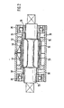
- FIG. 2 shows a longitudinal section through a torque sensor.
- the engine 10 of a tractor 11 drives the rear axle 17 of the tractor 11 via a shaft 12, a clutch 13, a transmission J4, a shaft section 15 and the differential 16. Furthermore leads from the gearbox J4 Via a PTO clutch 18, a PTO shaft 19 to an agricultural attachment 20, for example a combine harvester or a baler.
- a torque sensor 21 is arranged on the PTO shaft 19 and is connected to an amplifier 23 via an electrical line 22. From this, an electrical line 24 leads to control electronics 25, which is in operative connection with the transmission 14 and with the additional device 20 or with the PTO clutch 18.
- the active connection of the control electronics 25 with the PTO clutch 18 is possible alone or in addition to the active connection with the transmission 14 and the additional device 20, depending on whether the additional device 20 is to be regulated or controlled.
- the control electronics 25 can thus be both an electronic control device and an electronic control device.
- the torque sensor 21 works according to the so-called eddy current measuring method and is shown in more detail in FIG. 2. It has a sleeve-shaped housing 28 which is mounted on the PTO shaft 19 by means of ball bearings 29.
- the PTO shaft 19 is designed in the region of the housing 28 as a torsion shaft.
- Inside the housing 28, an inner and an outer slot sleeve 30 and 31 are arranged on the PTO shaft 19, each adjoining the ball bearing 29.
- the outer slot sleeve 31 has slots 32 milled in the longitudinal direction.
- two rows of slots 33, 34 are formed, which are each offset by one slot width.
- This output signal is amplified in the amplifier 23 and fed to the control electronics 25 and compared there with a predetermined target value.
- a setpoint e.g. the maximum torque to be transmitted can be set in the control electronics 25. If the torque transmitted from the power take-off shaft 19 to the additional device 20 now exceeds the predetermined target value, the control electronics 25 switches the gear ratio for the power take-off shaft 19 in the transmission 14 until the predetermined target value is again fallen below. This prevents the additional device 20 from being overloaded.
- control electronics 25 it is possible for the control electronics 25 to switch off the PTO clutch 18 in order to prevent the additional device 20 from being overloaded.
Landscapes
- Physics & Mathematics (AREA)
- Life Sciences & Earth Sciences (AREA)
- Electromagnetism (AREA)
- General Physics & Mathematics (AREA)
- Engineering & Computer Science (AREA)
- Mechanical Engineering (AREA)
- Soil Sciences (AREA)
- Environmental Sciences (AREA)
- Hydraulic Clutches, Magnetic Clutches, Fluid Clutches, And Fluid Joints (AREA)
- Agricultural Machines (AREA)
Applications Claiming Priority (2)
| Application Number | Priority Date | Filing Date | Title |
|---|---|---|---|
| DE3434825 | 1984-09-22 | ||
| DE19843434825 DE3434825A1 (de) | 1984-09-22 | 1984-09-22 | Einrichtung zum regeln und steuern des antriebs eines an einem landwirtschaftlichen arbeitsfahrzeug angehaengten arbeitsgeraets |
Publications (3)
| Publication Number | Publication Date |
|---|---|
| EP0175916A2 true EP0175916A2 (fr) | 1986-04-02 |
| EP0175916A3 EP0175916A3 (en) | 1987-09-09 |
| EP0175916B1 EP0175916B1 (fr) | 1989-07-26 |
Family
ID=6246063
Family Applications (1)
| Application Number | Title | Priority Date | Filing Date |
|---|---|---|---|
| EP85110309A Expired EP0175916B1 (fr) | 1984-09-22 | 1985-08-17 | Dispositif de réglage et de pilotage de l'entraînement d'un outil monté sur un tracteur agricole |
Country Status (2)
| Country | Link |
|---|---|
| EP (1) | EP0175916B1 (fr) |
| DE (2) | DE3434825A1 (fr) |
Cited By (6)
| Publication number | Priority date | Publication date | Assignee | Title |
|---|---|---|---|---|
| EP0208892A3 (en) * | 1985-07-12 | 1988-06-15 | Robert Bosch Gmbh | Device for controlling the driving unit of a working implement attached to an agricultural vehicle |
| EP0443325A1 (fr) * | 1990-01-19 | 1991-08-28 | Klöckner-Humboldt-Deutz Aktiengesellschaft | Dispositif d'accouplement hydraulique pour arbre de transmission sur tracteurs |
| EP1344443A1 (fr) * | 2002-03-12 | 2003-09-17 | Lemken GmbH & Co. KG | Outil pour le travail du sol |
| EP2064933A1 (fr) * | 2007-11-28 | 2009-06-03 | Robert Bosch GmbH | Entraînement de roulement pour appareils de travail |
| EP2151156A3 (fr) * | 2008-08-07 | 2010-04-21 | Deere & Company | Système d'entraînement et procédé d'entraînement d'un appareil de travail agricole |
| US10091942B2 (en) | 2015-09-03 | 2018-10-09 | Agco Corporation | Baler with automated positioning of plunger |
Families Citing this family (7)
| Publication number | Priority date | Publication date | Assignee | Title |
|---|---|---|---|---|
| DE3642502A1 (de) * | 1986-12-12 | 1988-06-23 | Amazonen Werke Dreyer H | Landwirtschaftliche geraetekombination |
| DE4239530C2 (de) * | 1992-11-25 | 2001-09-06 | Same Deutz Fahr Spa | Variabler Zapfwellenantrieb |
| DE19950138C1 (de) * | 1999-10-18 | 2000-12-28 | Josef Fischer | Zusatzantriebsmodul für einen landwirtschaftlichen Schlepper |
| DE102004009260A1 (de) | 2004-02-26 | 2005-09-29 | Zf Friedrichshafen Ag | Verfahren zum Betrieb einer mit einem Antriebsmotor gekoppelten Wegzapfwelle |
| DE102005005556B4 (de) * | 2005-02-07 | 2016-02-11 | Alois Pöttinger Maschinenfabrik Gmbh | Vorrichtung zur Steuerung einer landwirtschaftlichen Erntemaschine |
| DE102007018321A1 (de) | 2007-04-18 | 2008-10-23 | Alois Pöttinger Maschinenfabrik Gmbh | Erntemaschine |
| DE102019217298A1 (de) | 2019-11-08 | 2021-05-12 | Deere & Company | Antriebsanordnung für ein landwirtschaftliches Arbeitsgerät mit mechanischer Überlastkupplung und selbsttätiger Anpassung des Abschaltmoments |
Family Cites Families (5)
| Publication number | Priority date | Publication date | Assignee | Title |
|---|---|---|---|---|
| US3319464A (en) * | 1966-07-11 | 1967-05-16 | Mecca Cable & Service Inc | Torque meter |
| DE2951148C2 (de) * | 1979-12-19 | 1984-04-19 | Robert Bosch Gmbh, 7000 Stuttgart | Meßeinrichtung für einen Drehwinkel und/oder ein Drehoment |
| DE3008584A1 (de) * | 1980-03-06 | 1981-09-17 | Robert Bosch Gmbh, 7000 Stuttgart | Schaltungsanordnung zur erfassung von drehgroessen einer welle |
| US4416161A (en) * | 1981-09-14 | 1983-11-22 | Rockwell International Corporation | Method and apparatus for measuring torque |
| DE3307105A1 (de) * | 1982-03-17 | 1983-09-22 | Robert Bosch Gmbh, 7000 Stuttgart | Messeinrichtung fuer einen drehwinkel und/oder ein drehmoment |
-
1984
- 1984-09-22 DE DE19843434825 patent/DE3434825A1/de not_active Withdrawn
-
1985
- 1985-08-17 DE DE8585110309T patent/DE3571738D1/de not_active Expired
- 1985-08-17 EP EP85110309A patent/EP0175916B1/fr not_active Expired
Cited By (7)
| Publication number | Priority date | Publication date | Assignee | Title |
|---|---|---|---|---|
| EP0208892A3 (en) * | 1985-07-12 | 1988-06-15 | Robert Bosch Gmbh | Device for controlling the driving unit of a working implement attached to an agricultural vehicle |
| EP0443325A1 (fr) * | 1990-01-19 | 1991-08-28 | Klöckner-Humboldt-Deutz Aktiengesellschaft | Dispositif d'accouplement hydraulique pour arbre de transmission sur tracteurs |
| EP1344443A1 (fr) * | 2002-03-12 | 2003-09-17 | Lemken GmbH & Co. KG | Outil pour le travail du sol |
| EP2064933A1 (fr) * | 2007-11-28 | 2009-06-03 | Robert Bosch GmbH | Entraînement de roulement pour appareils de travail |
| EP2151156A3 (fr) * | 2008-08-07 | 2010-04-21 | Deere & Company | Système d'entraînement et procédé d'entraînement d'un appareil de travail agricole |
| US8577559B2 (en) | 2008-08-07 | 2013-11-05 | Deere & Company | Drive arrangement and process for the drive of an agricultural implement |
| US10091942B2 (en) | 2015-09-03 | 2018-10-09 | Agco Corporation | Baler with automated positioning of plunger |
Also Published As
| Publication number | Publication date |
|---|---|
| EP0175916A3 (en) | 1987-09-09 |
| DE3571738D1 (en) | 1989-08-31 |
| EP0175916B1 (fr) | 1989-07-26 |
| DE3434825A1 (de) | 1986-04-03 |
Similar Documents
| Publication | Publication Date | Title |
|---|---|---|
| EP0175916B1 (fr) | Dispositif de réglage et de pilotage de l'entraînement d'un outil monté sur un tracteur agricole | |
| EP1293697B1 (fr) | Procédure et dispositif de commande d'embrayage | |
| DE19731433C2 (de) | Drehmomentsensor | |
| DE69815725T2 (de) | Steuerung für Servo-Schaltung | |
| DE3112714C1 (de) | Vorrichtung zum Messen und UEberwachen des Antriebes an einem landwirtschaftlichen Anbau- oder Anhaengegeraet | |
| DE19951185B4 (de) | Drehmomentsensor | |
| DE102018129119A1 (de) | Fahrwerksaktuator für eine Hinterachslenkung | |
| EP0560143B1 (fr) | Capteur de position de déterminer le déplacement rotatif d'un arbre | |
| EP2697619A1 (fr) | Combinaison d'un arbre d'entraînement transmettant un couple et d'un arrangement de palier sur lequel l'arbre est monté | |
| DE112019000464T5 (de) | Einrichtung zur verwendung beim drehen lenkbarer fahrzeugräder | |
| DE2527055C2 (de) | Telemanipulator | |
| DE1960298C2 (de) | Einrichtung zur Überwachung eines landwirtschaftlich nutzbaren Motorfahrzeugs | |
| DE3612763A1 (de) | Elektrohydraulische hubwerks-regeleinrichtung | |
| DE19756239A1 (de) | Vorgelege für Vierradantrieb | |
| EP0208892B1 (fr) | Dispositif pour régler ou commander la motorisation d'un outillage accroché à un véhicule agricole | |
| DE10037692B4 (de) | Elektrische Servolenkungsvorrichtung | |
| EP0176725A2 (fr) | Dispositif de réglage de l'effort de traction d'un outil monté sur un tracteur agricole | |
| DE602005000165T2 (de) | Elektrische Servolenkeinrichtung für ein Kraftfahrzeug, Lenkanordnung mit einer solchen Servolenkeinrichtung und mit einer solchen Lenkanordnung ausgerüstetes Kraftfahrzeug | |
| DE3824372A1 (de) | Getriebe mit ueberlastsicherung, insbesondere fuer kettenantriebe bei bergbaumaschinen, wie vor allem kohlenhobel | |
| EP3636060B1 (fr) | Procédé de fonctionnement d'une combinaison d'appareil de travail et de véhicule de travail, système pour une combinaison d'appareil de travail et de véhicule de travail et combinaison d'appareil de travail et de véhicule de travail | |
| EP3298871B1 (fr) | Machine agricole , procédé de détéction d'une charge mécanique sur un élément d' une machine agricole | |
| DE3440492A1 (de) | Verfahren und einrichtung zum automatischen vermindern des relativschlupfes eines achswellenpaares eines kraftfahrzeuges | |
| EP1199550A2 (fr) | Dispositif pour mesurer le couple de torsion dans un dispositif d'entraínement | |
| DE2637006A1 (de) | Verfahren zur lenkungssteuerung eines landfahrzeuges und steuersystem zur durchfuehrung dieses verfahrens | |
| DE102022212917A1 (de) | Abtriebswellenstummel für ein Nebenabtriebsgetriebe, Nebenabtriebsgetriebe und Kraftfahrzeug |
Legal Events
| Date | Code | Title | Description |
|---|---|---|---|
| PUAI | Public reference made under article 153(3) epc to a published international application that has entered the european phase |
Free format text: ORIGINAL CODE: 0009012 |
|
| AK | Designated contracting states |
Kind code of ref document: A2 Designated state(s): DE FR GB IT |
|
| PUAL | Search report despatched |
Free format text: ORIGINAL CODE: 0009013 |
|
| AK | Designated contracting states |
Kind code of ref document: A3 Designated state(s): DE FR GB IT |
|
| 17P | Request for examination filed |
Effective date: 19880206 |
|
| 17Q | First examination report despatched |
Effective date: 19880509 |
|
| GRAA | (expected) grant |
Free format text: ORIGINAL CODE: 0009210 |
|
| AK | Designated contracting states |
Kind code of ref document: B1 Designated state(s): DE FR GB IT |
|
| GBT | Gb: translation of ep patent filed (gb section 77(6)(a)/1977) | ||
| REF | Corresponds to: |
Ref document number: 3571738 Country of ref document: DE Date of ref document: 19890831 |
|
| ET | Fr: translation filed | ||
| ITF | It: translation for a ep patent filed | ||
| PLBE | No opposition filed within time limit |
Free format text: ORIGINAL CODE: 0009261 |
|
| STAA | Information on the status of an ep patent application or granted ep patent |
Free format text: STATUS: NO OPPOSITION FILED WITHIN TIME LIMIT |
|
| 26N | No opposition filed | ||
| ITTA | It: last paid annual fee | ||
| PGFP | Annual fee paid to national office [announced via postgrant information from national office to epo] |
Ref country code: GB Payment date: 19920807 Year of fee payment: 8 |
|
| PGFP | Annual fee paid to national office [announced via postgrant information from national office to epo] |
Ref country code: FR Payment date: 19920827 Year of fee payment: 8 |
|
| PG25 | Lapsed in a contracting state [announced via postgrant information from national office to epo] |
Ref country code: GB Effective date: 19930817 |
|
| GBPC | Gb: european patent ceased through non-payment of renewal fee |
Effective date: 19930817 |
|
| PG25 | Lapsed in a contracting state [announced via postgrant information from national office to epo] |
Ref country code: FR Effective date: 19940429 |
|
| REG | Reference to a national code |
Ref country code: FR Ref legal event code: ST |
|
| PGFP | Annual fee paid to national office [announced via postgrant information from national office to epo] |
Ref country code: DE Payment date: 19941026 Year of fee payment: 10 |
|
| PG25 | Lapsed in a contracting state [announced via postgrant information from national office to epo] |
Ref country code: DE Effective date: 19960501 |