EP0176084A2 - Machine pour épandre des matériaux granulés latéralement - Google Patents
Machine pour épandre des matériaux granulés latéralement Download PDFInfo
- Publication number
- EP0176084A2 EP0176084A2 EP85112122A EP85112122A EP0176084A2 EP 0176084 A2 EP0176084 A2 EP 0176084A2 EP 85112122 A EP85112122 A EP 85112122A EP 85112122 A EP85112122 A EP 85112122A EP 0176084 A2 EP0176084 A2 EP 0176084A2
- Authority
- EP
- European Patent Office
- Prior art keywords
- linkage
- machine according
- drive element
- side arm
- machine
- Prior art date
- Legal status (The legal status is an assumption and is not a legal conclusion. Google has not performed a legal analysis and makes no representation as to the accuracy of the status listed.)
- Granted
Links
Images


Classifications
-
- A—HUMAN NECESSITIES
- A01—AGRICULTURE; FORESTRY; ANIMAL HUSBANDRY; HUNTING; TRAPPING; FISHING
- A01M—CATCHING, TRAPPING OR SCARING OF ANIMALS; APPARATUS FOR THE DESTRUCTION OF NOXIOUS ANIMALS OR NOXIOUS PLANTS
- A01M7/00—Special adaptations or arrangements of liquid-spraying apparatus for purposes covered by this subclass
- A01M7/005—Special arrangements or adaptations of the spraying or distributing parts, e.g. adaptations or mounting of the spray booms, mounting of the nozzles, protection shields
- A01M7/0071—Construction of the spray booms
- A01M7/0075—Construction of the spray booms including folding means
Definitions
- the invention relates to a machine for discharging, in particular, granular material with a storage container and a distributor rod, which in the operating position projects laterally beyond the storage container transversely to the direction of travel on both sides, each with a side arm, each side arm being divided into at least two rod parts which can be moved relative to one another, the storage container facing inner or first linkage part is articulated to the frame of the machine by means of an inner or first joint with an axis running approximately in the direction of travel and by means of an outer or second joint to the outer or second linkage part, the linkage parts of each side arm also being connected to one another via controls in such a way that when the first linkage part is pivoted by means of a drive element articulated on it and on the machine frame about the axis of the first joint, the second linkage part undergoes a corresponding, inevitable folding movement performs the second joint, and furthermore the outer linkage part is connected to the machine frame by a length-adjustable clamping element.
- Such a machine with forced movement of three linkage parts of each side arm controlled by the control elements is already known from DE-OS 32 30 750.
- the drive elements serve to raise or lower the inner linkage parts, as a result of which the outer linkage parts are forcibly matched to the movements of the inner linkage parts as a result of the control elements and are thus folded together until the non-operating position is reached or the operating position are unfolded.
- the linkage parts of both side arms are stretched apart horizontally and held in this stretched state by means of the tensioning elements.
- turnbuckles are provided for readjustment.
- the invention has for its object to develop a machine of the type mentioned with a dependent on the movement of the inner linkage parts of the movement of the outer linkage parts of the side boom so that the linkage can be at least partially adapted to the terrain contours.
- a lifting device for angling the side arms is arranged in the stretched state between the frame of the machine and the second linkage parts, and in that at least one of the linkages of each drive element relative to the respective first linkage part and / or movable to the machine frame or, in the case of a fixed linkage, each drive element can be actuated simultaneously with the associated lifting device in order to enable the pivoting movement of the same when the side arms are angled.
- the relatively movable articulation of the drive element on the side arm or on the machine frame or on both enables the first linkage part and thus the entire side arm to perform the pivoting movement caused by the actuation of the lifting device when angling or lowering, without a folding movement of the outer linkage parts.
- the articulation can advantageously be moved in a guide designed as an elongated hole.
- the effect achieved by the relatively movable articulation can also be achieved if the drive element is actuated simultaneously with the associated lifting device. This can be easily achieved, for example, in that, when the drive element and the lifting device are designed as lifting cylinders, both cylinders are connected to a common circuit for the actuating medium, preferably in parallel.
- the lifting devices In order to transmit their movement to the respective second linkage part in a simple manner when the lifting devices are actuated, the lifting devices preferably engage the respective tensioning element.
- This also has the advantage of retrofitting conventional machines already in use in a simple manner with the lifting device, in particular if the latter is designed as a lifting cylinder, for example a hydraulic cylinder.
- the angle of the side arms can be limited by the stroke of the respective lifting cylinder of the drive elements.
- the same function can also be performed by the lifting cylinder of the lifting device or by the guide designed as an elongated hole for the articulation of the drive element on the side arm.
- each lifting cylinder can be provided with two piston rods, one of which is connected to the respective first linkage part and the other of which is connected to the respective clamping element. It is advantageous here to deflect the tensioning elements via rollers.
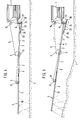
- the fertilizer spreader shown in Figures 1 to 3 has a machine frame and a storage container 1 and is designed as an attachment for attachment to the three-point coupling of a tractor.
- Pipelines 2 connected to it are arranged below the storage container 1 and have different lengths and extend laterally outwards to a different extent.
- the pipelines 2 are accommodated in a distribution linkage which projects laterally beyond the storage container 1 with a side arm 3 on both sides by a multiple of the width of the storage container 1.
- the pipes 2 are connected to a blower driven by a tractor shaft via a propeller shaft and not shown.
- Granular material located in the storage container 1 is in adjustable amounts conveyed into the pipelines 2 via openings, not shown. Here the material is caught by the air flowing through the pipelines and blown to the respective outflow ends of the pipelines, from where it is distributed in a broad distribution on the floor surface 4.
- Each side arm 3 consists of three mutually movable linkage parts 7, 9, 10, which are connected to one another via control elements 5 and are held in the operating position shown in FIGS. 1 and 2 by a tensioning element 6 designed as a tether.
- the inner or first linkage part 7 of each side arm 3 which is arranged closest to the storage container 1 is pivotably attached to the machine frame via a horizontal axis 8 extending in the direction of travel.
- the outer linkage parts, namely the second and third linkage parts 9 and 10 are connected to the inner linkage part 7 of each side boom and are pivotally connected to the first linkage part 7 or to one another via horizontal axes 11 and 12 also running in the direction of travel.
- the outermost or third linkage part 10 can swivel against an element designed as a spring, not shown, when it encounters an obstacle in the opposite direction. This prevents damage to the distributor linkage.
- a drive element 18 in the form of a hydraulic cylinder 19 articulated on the one hand on the machine frame and on the other hand with the articulation 21 on the first linkage part 7 is arranged below the inner or first linkage part 7 of each side arm 3.
- the linkage 21 of the hydraulic cylinder 19 is designed to be movable relative to the first linkage part 7.
- the free end of the piston 20 of the hydraulic cylinder 19 is guided in a guide which is fastened to the first linkage part 7 and is designed as an elongated hole 22.
- a lifting device 14 in the form of a substantially vertically oriented hydraulic cylinder 13 is arranged on the machine frame above the first rod part 7 of each side arm 3.
- the tensioning element 6 is fastened at one end to the control element 5 connecting the linkage parts 7 and 9 and at its other end after deflection around a deflection roller 15 arranged at the upper end of the hydraulic cylinder 13 with the upper end of a piston rod 17 of the hydraulic cylinder 13 which can be extended in the direction of the arrow 16 connected.
- each side arm 3 of the distributor In the operating position shown in Fig. 1, each side arm 3 of the distributor is in a fully stretched state in the horizontal. Accordingly, the pistons 17 and 20 of the hydraulic cylinders 13 and 19 are also in the retracted state. As soon as fertilizer is now to be applied in uneven terrain, each side boom 3 can be raised from the horizontal by a certain angle ⁇ and thus at least partially adapted to the terrain contour. This adjustment takes place in that the hydraulic cylinder 13 connected to the tractor hydraulics is acted upon by pressure oil. Accordingly, the piston 17 extends out of the cylinder 13 at the bottom and lifts the side arm 3, which remains in the fully extended state, by the angle ′′ via the tensioning element 6. The pivotal movement of the side arm 3 occurs, although the hydraulic cylinder 19 of the drive element 18 is not acted upon, unimpeded, since the linkage 21 of the hydraulic cylinder 19 can slide in the slot 22 in a relative movement to the side arm 3.
- both hydraulic cylinders 13 and 19 must be connected in parallel to a common hydraulic circuit.
- the piston 17 of the cylinder 13 extends and lifts the side arm 3 by the angle 0 (in the manner described above.
- the piston 20 of the hydraulic cylinder 19 also extends a small distance and thus enables the side arm 3 to be raised by this angle ⁇ , the piston 20 extending only due to the lifting of the side boom 3 by the piston 17.
- both cylinders 13 and 19 are further pressurized with oil, the piston 17 of the former cylinder extends to the end stop, and the piston 20 of the 3 in a vertical plane, whereby the tensioning element becomes a control cable and ensures that the side boom is inevitably folded into the transport or non-operating position shown in Fig. 7.
- These two work processes are made possible by the Use different pressure levels for cylinders 13 and 19. For da s Lifting by means of the tensioning element 6 through the cylinder 13 requires a lower pressure than for the folding through the cylinder 19.
- the hydraulic cylinders 13 and 19 of the side arms 3 are each replaced by a single hydraulic cylinder 23 which is articulated below the side arm 3 transversely to the direction of travel on the suspension 24 of the machine frame.
- the cylinder 23 has two piston rods 25 and 26 on.
- the free end of the former is articulated on the inner or first linkage part 7 in a position fixed relative to this linkage part.
- the latter piston rod 26 is connected to the tensioning element 6, which is deflected via the deflection roller 15 and an additional deflection roller 27.
- each side arm is held by the tensioning element 6 designed as a tether, the pistons 25 and 26 of the hydraulic cylinder 23 being retracted. If the cylinder 23 is pressurized with pressure oil, the piston 26 first extends and lifts the side arm 3 by the angle ⁇ up to the position shown in FIG. 5 via the tensioning element 6. The piston 25 also extends a short distance. When the hydraulic cylinder 23 is further acted upon, the piston 26 extends further to the end stop and the piston 25 folds the side arm 3 together in the manner described above.
Landscapes
- Life Sciences & Earth Sciences (AREA)
- Engineering & Computer Science (AREA)
- Insects & Arthropods (AREA)
- Pest Control & Pesticides (AREA)
- Wood Science & Technology (AREA)
- Zoology (AREA)
- Environmental Sciences (AREA)
- Agricultural Machines (AREA)
- Catching Or Destruction (AREA)
Applications Claiming Priority (2)
| Application Number | Priority Date | Filing Date | Title |
|---|---|---|---|
| DE3435086 | 1984-09-25 | ||
| DE3435086 | 1984-09-25 |
Publications (3)
| Publication Number | Publication Date |
|---|---|
| EP0176084A2 true EP0176084A2 (fr) | 1986-04-02 |
| EP0176084A3 EP0176084A3 (en) | 1987-02-04 |
| EP0176084B1 EP0176084B1 (fr) | 1990-03-21 |
Family
ID=6246260
Family Applications (1)
| Application Number | Title | Priority Date | Filing Date |
|---|---|---|---|
| EP85112122A Expired - Lifetime EP0176084B1 (fr) | 1984-09-25 | 1985-09-25 | Machine pour épandre des matériaux granulés latéralement |
Country Status (2)
| Country | Link |
|---|---|
| EP (1) | EP0176084B1 (fr) |
| DE (1) | DE3576635D1 (fr) |
Cited By (8)
| Publication number | Priority date | Publication date | Assignee | Title |
|---|---|---|---|---|
| EP0269880A1 (fr) * | 1986-11-20 | 1988-06-08 | ACCORD Landmaschinen Heinrich Weiste & Co. GmbH | Epandeur d'engrais comportant des rampes et un dispositif de levage |
| WO1992000670A1 (fr) * | 1990-07-04 | 1992-01-23 | Roger Benest | Procede et appareil de pulverisation des cultures |
| US5507435A (en) * | 1991-08-06 | 1996-04-16 | Benest Engineering Limited | Method and apparatus for crop spraying including an articulated boom sprayer |
| FR2732858A1 (fr) * | 1995-04-13 | 1996-10-18 | Sarl Jm Casseron | Rampe d'ependage de boues et lisiers |
| EP2186405A1 (fr) | 2008-11-12 | 2010-05-19 | Leeb Mechanik GmbH | Tige de pulvérisation et son procédé de commande |
| EP3357333A1 (fr) * | 2017-02-07 | 2018-08-08 | Deere & Company | Machine d'épandage agricole à commande automatique d'amortissement de la r ampe d'épandage |
| KR20180003426U (ko) * | 2017-05-30 | 2018-12-10 | (주)온누리기계 | 자동 폴딩 붐스프레이어 |
| IT202000004948A1 (it) * | 2020-03-09 | 2021-09-09 | Toselli Soc A Responsabilita Limitata | Irroratrice con barra idraulica |
Family Cites Families (8)
| Publication number | Priority date | Publication date | Assignee | Title |
|---|---|---|---|---|
| US3055594A (en) * | 1960-01-04 | 1962-09-25 | Burg Mfg Company | Boom type spraying means |
| DE2216014A1 (de) * | 1972-04-01 | 1973-10-11 | Troester A J Fa | Vorrichtung zum wechselseitigen betaetigen von spurreissern |
| US4074766A (en) * | 1976-05-24 | 1978-02-21 | Orthman Manufacturing Inc. | Floating folding tool bar having a lock means |
| FR2382171A1 (fr) * | 1977-03-04 | 1978-09-29 | Nodet Gougis | Epandeur pneumatique a rampes d'epandage pivotantes |
| US4427154A (en) * | 1982-05-17 | 1984-01-24 | Mercil Leroy J | Boom suspension and lift assembly |
| DE3230489C2 (de) * | 1982-08-17 | 1988-10-20 | Accord-Landmaschinen Heinrich Weiste & Co Gmbh, 4770 Soest | Ausgleichsvorrichtung für die Seitenausleger für Düngerstreuer |
| DE3242932C2 (de) * | 1982-11-20 | 1985-04-25 | Amazonen-Werke H. Dreyer Gmbh & Co Kg, 4507 Hasbergen | Spurreißer für eine landwirtschaftliche Maschine |
| US4530405A (en) * | 1984-03-23 | 1985-07-23 | Deere & Co. | Planter row marker |
-
1985
- 1985-09-25 DE DE8585112122T patent/DE3576635D1/de not_active Expired - Lifetime
- 1985-09-25 EP EP85112122A patent/EP0176084B1/fr not_active Expired - Lifetime
Cited By (11)
| Publication number | Priority date | Publication date | Assignee | Title |
|---|---|---|---|---|
| EP0269880A1 (fr) * | 1986-11-20 | 1988-06-08 | ACCORD Landmaschinen Heinrich Weiste & Co. GmbH | Epandeur d'engrais comportant des rampes et un dispositif de levage |
| WO1992000670A1 (fr) * | 1990-07-04 | 1992-01-23 | Roger Benest | Procede et appareil de pulverisation des cultures |
| AU645021B2 (en) * | 1990-07-04 | 1994-01-06 | Micron Sprayers Limited | Method and apparatus for crop spraying |
| US5326030A (en) * | 1990-07-04 | 1994-07-05 | Benest Engineering Limited | Method and apparatus for crop spraying |
| US5507435A (en) * | 1991-08-06 | 1996-04-16 | Benest Engineering Limited | Method and apparatus for crop spraying including an articulated boom sprayer |
| FR2732858A1 (fr) * | 1995-04-13 | 1996-10-18 | Sarl Jm Casseron | Rampe d'ependage de boues et lisiers |
| EP2186405A1 (fr) | 2008-11-12 | 2010-05-19 | Leeb Mechanik GmbH | Tige de pulvérisation et son procédé de commande |
| EP3357333A1 (fr) * | 2017-02-07 | 2018-08-08 | Deere & Company | Machine d'épandage agricole à commande automatique d'amortissement de la r ampe d'épandage |
| KR20180003426U (ko) * | 2017-05-30 | 2018-12-10 | (주)온누리기계 | 자동 폴딩 붐스프레이어 |
| KR200489011Y1 (ko) | 2017-05-30 | 2019-04-17 | (주)온누리기계 | 자동 폴딩 붐스프레이어 |
| IT202000004948A1 (it) * | 2020-03-09 | 2021-09-09 | Toselli Soc A Responsabilita Limitata | Irroratrice con barra idraulica |
Also Published As
| Publication number | Publication date |
|---|---|
| EP0176084A3 (en) | 1987-02-04 |
| DE3576635D1 (de) | 1990-04-26 |
| EP0176084B1 (fr) | 1990-03-21 |
Similar Documents
| Publication | Publication Date | Title |
|---|---|---|
| DE2713270B2 (de) | Tragbalken für landwirtschaftliche Geräte mit wenigstens einem verschwenkbaren Balkenteil | |
| DE9312843U1 (de) | Rasentraktor mit wenigstens einem Spindelmäher | |
| DE112013001318T5 (de) | Geräterahmen mit nach vorne faltbaren Flügeln | |
| DE2801116B2 (de) | Klappbarer Geräteträger mit zwei Werkzeugtragrahmen | |
| EP0063774A1 (fr) | Système d'attelage pour un tracteur agricole | |
| EP4492955B1 (fr) | Outil agricole | |
| DE2837668A1 (de) | Hebebuehne | |
| DE2743087C3 (de) | Lenkeinrichtung für mindestens ein rückwärtiges Laufrad eines Pfluges | |
| EP0176084B1 (fr) | Machine pour épandre des matériaux granulés latéralement | |
| EP3028557B1 (fr) | Faucheuse et procédé de fonctionnement d'une faucheuse | |
| DE2160751C3 (de) | Maschine zum Ausbringen von gekörnten und pulverförmigen Materialien | |
| EP3403562B1 (fr) | Dispositif de ventouse pour une machine de nettoyage de sol et machine de nettoyage de sol | |
| EP4252504A1 (fr) | Axe de réglage | |
| DE1658034A1 (de) | Ausleger-Schwenkvorrichtung | |
| EP0224166A2 (fr) | Rampe de pulvérisation pour un pulvérisateur agricole | |
| DE3751568T2 (de) | Landmaschine. | |
| DE202005011305U1 (de) | Vorrichtung zur Seitenstabilisierung der Unterlenker einer Geräteanbauvorrichtung eines Ackerschleppers | |
| EP3367775B1 (fr) | Bâti d'engin agricole | |
| DE19708316A1 (de) | Fahrbares Arbeitsgerät | |
| EP1529427B1 (fr) | Machine agricole à travail du sol et/ou de semis | |
| DE2348164A1 (de) | Hocharbeitsgeruest | |
| AT502053B1 (de) | Anbauvorrichtung für eine landmaschine | |
| EP3598882A1 (fr) | Accessoire agricole | |
| DE2447921A1 (de) | Vorrichtung zum raeumen von flaechen, insbesondere forstflaechen | |
| CH657882A5 (de) | Schneeraeumeinrichtung. |
Legal Events
| Date | Code | Title | Description |
|---|---|---|---|
| PUAI | Public reference made under article 153(3) epc to a published international application that has entered the european phase |
Free format text: ORIGINAL CODE: 0009012 |
|
| AK | Designated contracting states |
Kind code of ref document: A2 Designated state(s): DE FR GB |
|
| PUAL | Search report despatched |
Free format text: ORIGINAL CODE: 0009013 |
|
| AK | Designated contracting states |
Kind code of ref document: A3 Designated state(s): DE FR GB |
|
| 17P | Request for examination filed |
Effective date: 19870520 |
|
| 17Q | First examination report despatched |
Effective date: 19890417 |
|
| GRAA | (expected) grant |
Free format text: ORIGINAL CODE: 0009210 |
|
| AK | Designated contracting states |
Kind code of ref document: B1 Designated state(s): DE FR GB |
|
| ET | Fr: translation filed | ||
| REF | Corresponds to: |
Ref document number: 3576635 Country of ref document: DE Date of ref document: 19900426 |
|
| GBT | Gb: translation of ep patent filed (gb section 77(6)(a)/1977) | ||
| PGFP | Annual fee paid to national office [announced via postgrant information from national office to epo] |
Ref country code: GB Payment date: 19900820 Year of fee payment: 6 |
|
| PGFP | Annual fee paid to national office [announced via postgrant information from national office to epo] |
Ref country code: FR Payment date: 19900906 Year of fee payment: 6 |
|
| PGFP | Annual fee paid to national office [announced via postgrant information from national office to epo] |
Ref country code: DE Payment date: 19901030 Year of fee payment: 6 |
|
| PLBE | No opposition filed within time limit |
Free format text: ORIGINAL CODE: 0009261 |
|
| STAA | Information on the status of an ep patent application or granted ep patent |
Free format text: STATUS: NO OPPOSITION FILED WITHIN TIME LIMIT |
|
| 26N | No opposition filed | ||
| PG25 | Lapsed in a contracting state [announced via postgrant information from national office to epo] |
Ref country code: GB Effective date: 19910925 |
|
| GBPC | Gb: european patent ceased through non-payment of renewal fee | ||
| PG25 | Lapsed in a contracting state [announced via postgrant information from national office to epo] |
Ref country code: FR Effective date: 19920529 |
|
| PG25 | Lapsed in a contracting state [announced via postgrant information from national office to epo] |
Ref country code: DE Effective date: 19920602 |
|
| REG | Reference to a national code |
Ref country code: FR Ref legal event code: ST |