EP0176103B1 - Projecteur d'automobile - Google Patents
Projecteur d'automobile Download PDFInfo
- Publication number
- EP0176103B1 EP0176103B1 EP85112252A EP85112252A EP0176103B1 EP 0176103 B1 EP0176103 B1 EP 0176103B1 EP 85112252 A EP85112252 A EP 85112252A EP 85112252 A EP85112252 A EP 85112252A EP 0176103 B1 EP0176103 B1 EP 0176103B1
- Authority
- EP
- European Patent Office
- Prior art keywords
- lens
- heat
- layer
- automobile headlight
- headlight
- Prior art date
- Legal status (The legal status is an assumption and is not a legal conclusion. Google has not performed a legal analysis and makes no representation as to the accuracy of the status listed.)
- Expired
Links
- 239000000463 material Substances 0.000 claims description 20
- 239000004033 plastic Substances 0.000 claims description 17
- 230000005540 biological transmission Effects 0.000 claims description 9
- 239000011248 coating agent Substances 0.000 claims description 6
- 238000000576 coating method Methods 0.000 claims description 6
- 229910052751 metal Inorganic materials 0.000 claims description 4
- 239000002184 metal Substances 0.000 claims description 4
- 239000003973 paint Substances 0.000 claims description 4
- 239000011810 insulating material Substances 0.000 claims description 2
- 239000002775 capsule Substances 0.000 description 9
- 229910052782 aluminium Inorganic materials 0.000 description 7
- XAGFODPZIPBFFR-UHFFFAOYSA-N aluminium Chemical compound [Al] XAGFODPZIPBFFR-UHFFFAOYSA-N 0.000 description 7
- 229910052721 tungsten Inorganic materials 0.000 description 6
- 239000010937 tungsten Substances 0.000 description 6
- 239000000853 adhesive Substances 0.000 description 4
- 230000001070 adhesive effect Effects 0.000 description 4
- 230000004313 glare Effects 0.000 description 4
- 229910052736 halogen Inorganic materials 0.000 description 4
- 230000003287 optical effect Effects 0.000 description 4
- -1 tungsten halogen Chemical class 0.000 description 4
- 239000004417 polycarbonate Substances 0.000 description 3
- 229920000515 polycarbonate Polymers 0.000 description 3
- 239000004677 Nylon Substances 0.000 description 2
- 229910052500 inorganic mineral Inorganic materials 0.000 description 2
- 238000000034 method Methods 0.000 description 2
- 239000011707 mineral Substances 0.000 description 2
- 229920001778 nylon Polymers 0.000 description 2
- WFKWXMTUELFFGS-UHFFFAOYSA-N tungsten Chemical compound [W] WFKWXMTUELFFGS-UHFFFAOYSA-N 0.000 description 2
- 238000003466 welding Methods 0.000 description 2
- 229910000838 Al alloy Inorganic materials 0.000 description 1
- 239000004593 Epoxy Substances 0.000 description 1
- 229920004142 LEXAN™ Polymers 0.000 description 1
- 241000446313 Lamella Species 0.000 description 1
- 239000004418 Lexan Substances 0.000 description 1
- 230000002411 adverse Effects 0.000 description 1
- 238000007743 anodising Methods 0.000 description 1
- 238000004140 cleaning Methods 0.000 description 1
- 238000000151 deposition Methods 0.000 description 1
- 238000011161 development Methods 0.000 description 1
- 230000018109 developmental process Effects 0.000 description 1
- 230000009365 direct transmission Effects 0.000 description 1
- 238000009826 distribution Methods 0.000 description 1
- 230000000694 effects Effects 0.000 description 1
- 239000011888 foil Substances 0.000 description 1
- 239000011521 glass Substances 0.000 description 1
- 230000014759 maintenance of location Effects 0.000 description 1
- 230000002265 prevention Effects 0.000 description 1
- 230000005855 radiation Effects 0.000 description 1
- 238000007789 sealing Methods 0.000 description 1
- 239000000758 substrate Substances 0.000 description 1
Images

Classifications
-
- F—MECHANICAL ENGINEERING; LIGHTING; HEATING; WEAPONS; BLASTING
- F21—LIGHTING
- F21S—NON-PORTABLE LIGHTING DEVICES; SYSTEMS THEREOF; VEHICLE LIGHTING DEVICES SPECIALLY ADAPTED FOR VEHICLE EXTERIORS
- F21S41/00—Illuminating devices specially adapted for vehicle exteriors, e.g. headlamps
- F21S41/40—Illuminating devices specially adapted for vehicle exteriors, e.g. headlamps characterised by screens, non-reflecting members, light-shielding members or fixed shades
- F21S41/43—Illuminating devices specially adapted for vehicle exteriors, e.g. headlamps characterised by screens, non-reflecting members, light-shielding members or fixed shades characterised by the shape thereof
-
- F—MECHANICAL ENGINEERING; LIGHTING; HEATING; WEAPONS; BLASTING
- F21—LIGHTING
- F21S—NON-PORTABLE LIGHTING DEVICES; SYSTEMS THEREOF; VEHICLE LIGHTING DEVICES SPECIALLY ADAPTED FOR VEHICLE EXTERIORS
- F21S41/00—Illuminating devices specially adapted for vehicle exteriors, e.g. headlamps
- F21S41/20—Illuminating devices specially adapted for vehicle exteriors, e.g. headlamps characterised by refractors, transparent cover plates, light guides or filters
- F21S41/28—Cover glass
Definitions
- This invention relates to an automobile headlight wherein a shielding means is utilized to prevent glare to an oncoming -motorist during headlight operation within the designated automobile, more particularly, to an automobile headlight including a reflector, a plastic lens secured to said reflector, and a light source disposed within and surrounded by said reflector, means being located on or forming part of a preselected portion of said plastic lens for preventing transmission of visible light through said preselected portion of said lens and for preventing heat buildup on said lens during light source operation, said means partly comprising a heat insulating material.
- An automobile headlight according to the preamble of Claim 1 is known from GB-A-2 079 434 disclosing several possibilities for protecting a headlamp lens from heat damage, including face irregularities, a disc embedded within the lens, a disc secured to the lens, a disc spaced from the lens by an air cavity to allow heated air to pass therethrough, a lamella also allowing heat air passage, a spaced disc located on rods and attached to the reflector and a metallic foil glued to the lens.
- a critical requirement of the known material is that it be different from the lens material and that it must reflect to the headlamp's interior the thermal radiation of the light beam reflected by the reflector. Thus it reflects heat and also at least some of the light.
- the material used with this known technique does not involve the property of absorbing visible light.
- an automobile headlight as mentioned above which is characterized in that said means comprises a layer of heat reflecting material located on an internal surface of said lens relative to said light source, and heat insulating means being located adjacent said layer of heat reflecting material, and comprises means for absorbing visible light and emitting heat upon receipt of said visible light, said light absorbing and heat emitting means being spaced from said layer of heat reflecting material by said heat insulating means, and in that said heat reflecting material includes a first metallic layer, said light absorbing and heat emitting means comprises a second metallic layer having a dark coating thereon, and that said heat insulating means includes a substantially open area and further includes a plurality of support rods secured at one end to said first layer of metal in a spaced-apart relationship, said second layer of metal being positioned on a second, opposing end of each of said support rods so that the internal atmosphere of said headlight can pass around and between said support rods.
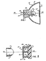
- Headlight 10 may be utilized as one of the lighting modules in a multi-headlight lighting system in which several (e.g., four) modules are employed on each side of the vehicle such that each module can in turn utilize a low wattage light source (e.g., tungsten halogen capsule).
- a low wattage light source e.g., tungsten halogen capsule.
- the lens 11 is plastic and is preferably secured to the front of the headlight's reflector component 13.
- Lens 11 has an overall height (top to bottom in Fig. 1) of only about 50 mm (two inches) to thus provide the compactness desired for a system such as described above.
- lens 11 is preferably of substantially rectangular configuration when viewed from the front of the headlight.
- reflector 13 is preferably paraboloidal in configuration to provide maximum reflection from the designated light source.
- Reflector 13 is also preferably of plastic material, and, more preferably, a polycarbonate (e.g., a plastic sold under the trademark Lexan by the General Electric Co.). Lens 11 is also of this material.
- Yet another plastic suitable for the reflector is mineral-filled nylon. Sealing of lens 11 to reflector 13 may be accomplished by using a suitable epoxy known in the art, or alternatively, by ultrasonic welding.
- lens 11 is hermetically sealed to the reflector at the forward, open portion thereof.
- the various lensing elements e.g. flutes which function to direct the light transmitted through lens 11 in the desired manner to produce the ultimate pattern may be located on either the internal or external surface of the lens.
- such elements are internally located to facilitate cleaning of lens 11 and to also substantially reduce dirt buildup on the lens outer surface as can readily occur during normal automobile operation.
- the preferred light source 15 for headlight 10 is a low wattage, tungsten halogen capsule 17 which is integrally mounted within reflector 13 and substantially surrounded by the reflector's internal reflecting surfaces.
- low wattage is meant a wattage within the range of only about ten to about twenty-five watts.
- Tungsten halogen lamps are well known in the art and typically include a coiled tungsten filament 19 within the capsule's glass envelope 21 and electrically connected to a pair of lead-in wires 23 which project externally of the capsule's press sealed end 25.
- the preferred filament 19 for capsule 17 is a coiled-coil (CC) filament which lies along the envelope's longitudinal axis.
- CC coiled-coil
- a coiled-coil tungsten filament lying orthogonal to this axis may be utilized. In either case, the filament is located within the reflector such that the reflector's focal point (FP) is substantially centered thereon. This in turn assures maximum light output to the designated reflecting surfaces.
- Light source 15 is hermetically sealed within reflector 13. This may be accomplished by providing a pair of apertures within the reflector's neck portion 27 and passing the lead-in wires 23 therethrough. These wires may then be sealed by ultrasonic welding after correct alignment of the capsule's filament 19 has occurred. As also seen in Fig. 1, capsule 17 is oriented such that filament 19 lies along the optical axis OA of the reflector. Although there has been shown and described a capsule containing only one filament therein, it is within the scope of the invention to utilize a light source wherein more than one filament is employed. The teachings herein are not limited to only tungsten halogen capsules as the light source.
- the tip (upper) portion of envelope 21 is facing means 31' and thus located relative (adjacent) thereto.
- light passing through the tip or upper portion of envelope 21 is prevented from directly passing through the central portion of the lens by means 31'.
- means 31' is deemed important because light passing through the envelope's tip portion is of uneven distribution and as such unacceptable for direct transmission through a lens. Provision of means 31' for substantially preventing this transmission thus serves to substantially reduce glare to an oncoming motorist. Because means 31' is centrally disposed on lens 11 relative to lamp 15, it is also able to substantially prevent much of the heat emitted by the tip portion of the lamp from building up on the central portion of the lens.
- means 31' is shown on a much larger scale to provide better illustration thereof.
- the tip portion of lamp 15 is also illustrated in its relative position to means 31' and lens 11.
- Means 31' comprises a layer of heat reflecting material 43 located on the internal surface of lens 11, heat insulating means 45 located adjacent material 43, and means 47 for absorbing the visible light from the tip portion of lamp 15 and for emitting heat upon receipt of said visible light. As shown, means 47 is spaced from the heat reflecting material 43 by insulating means 45.
- material 43 comprised a first thin metallic layer of preferably aluminum having a thickness of about 0,05 mm (0.002 inch).
- Means 47 comprised a second, thin metallic layer 49 of preferably aluminum having thereon a dark coating 51 which, as shown in Fig. 2, faced lamp 15.
- the dark coating can be black paint having a thickness of only about ten to twelve microns.
- means 31' was preferably of substantially round shape with the axis thereof coincident with optical axis OA-OA of reflector 13.
- the envelope 21 of adjacent lamp 15 was also of substantially cylindrical configuration, excluding the relatively flattened press-sealed end portion 25 thereof.
- means 31' had a diameter of only about 10,16 mm (0.400 inch) whereas the outer diameter of the corresponding cylindrical envelope 21 was about 6,35 mm (0.250 inch).
- Reflector 13 in turn possessed a focal point FP of about 7,62 mm (0.300 inch).
- the heat insulating means 45 comprises a substantially open region (or area) through which the internal atmosphere of headlight 10 will pass during headlight operation.
- a plurality (e.g., three) of support rods 53 are utilized, said rods arranged in a substantially triangular, spaced-apart orientation to enable passage of the described atmosphere therebetween (and around).
- Each rod 53 is preferably of plastic or the like material and is secured at one end thereof by a suitable adhesive to the first thin aluminum layer 43.
- Means 47, comprising the defined second aluminum substrate layer 49 having the coating of black paint 51 thereon, is thus secured by a suitable adhesive to the opposing ends of each support rod 53.
- each support rod 53 was comprised of a polycarbonate and possessed an overall length of only about 3 18mm (0.125 inch), while the corresponding, thicknesses for the second aluminum layer 49 and black paint 51 were about 0,05 mm (0.002 inch) and approximately then to twelve microns, respectively. Accordingly, means 31' possessed an overall thickness of only about 3,3 mm (0.130 inch). In addition. means 31' possessed a substantially round configuration and a diameter of only about 10,16 mm (0.400 inch).
- the first aluminum layer 43 was preferably applied using a suitable adhesive such as described above.
- Assembly of means 31' can be achieved by initially depositing or positioning the layer 43 on lens 11, thereafter individually positioning the support rods 53 in the described, triangular pattern, and, when secured, thereafter applying the double-layered means 47.
- an emblem means 61 in the form of a substantially cylindrical disc 63 is provided which is located in a central position (coaxial with optical axis OA-OA) on the front (external) surface of lens 11.
- Means 61 preferably includes an appropriate logo, symbol or lettering 65 to indicate the manufacturer of the invention.
- Means 61 can also include other information separate from or in addition to the above, including, for example, operating parameters (e.g., wattage).
- Means 61 is secured to lens 11 by providing disc 63 with an extending pin portion 67 which passes through respective openings centrally located with lens 11 and means 31.
- disc 63 In assembly, disc 63 is positioned on lens 11 such that pin portion 67 will pass through and extend from the internal surface of the lens. Means 31' (shown in a simplified manner only) is then located overthe extending pin portion 67, whereupon heat is applied to the extreme end of portion 67, causing it to deform (melt). As a result, a rivet or the like is formed to effectively secure means 31' in position as well as provide effective retention of the main body portion of disc 63 against the external lens surface.
- a suitable material for means 61 is plastic (e.g. the aforementioned polycarbonate or mineral-filled nylon). Such a plastic is understandably of the high temperature variety.
- Headlights using the teachings of the instant invention and possessing the dimensions and materials as cited above not only were capable of substantially reducing glare but also resulted in a significant reduction in temperature for the lens member.
- a temperature reduction from about 10 degrees to about 15 degrees Celsius was attained, based on an average operating temperature of about 115 degrees Celsius for a headlight containing a plastic lens and no heat buildup prevention means therein.
- the relative thicknesses of the various elements depicted in the drawings are provided for illustrative purposes only and are thus not meant to limit the invention. Specifically, the respective thicknesses as illustrated may not be to exact scale and thus representative of those values provided above.
Landscapes
- Engineering & Computer Science (AREA)
- General Engineering & Computer Science (AREA)
- Non-Portable Lighting Devices Or Systems Thereof (AREA)
- Lighting Device Outwards From Vehicle And Optical Signal (AREA)
Claims (7)
Applications Claiming Priority (2)
| Application Number | Priority Date | Filing Date | Title |
|---|---|---|---|
| US06/655,616 US4642514A (en) | 1984-09-28 | 1984-09-28 | Automobile headlight with combined heat and light shield |
| US655616 | 1984-09-28 |
Publications (2)
| Publication Number | Publication Date |
|---|---|
| EP0176103A1 EP0176103A1 (fr) | 1986-04-02 |
| EP0176103B1 true EP0176103B1 (fr) | 1989-07-12 |
Family
ID=24629636
Family Applications (1)
| Application Number | Title | Priority Date | Filing Date |
|---|---|---|---|
| EP85112252A Expired EP0176103B1 (fr) | 1984-09-28 | 1985-09-27 | Projecteur d'automobile |
Country Status (5)
| Country | Link |
|---|---|
| US (1) | US4642514A (fr) |
| EP (1) | EP0176103B1 (fr) |
| JP (1) | JPS61158604A (fr) |
| CA (1) | CA1239977A (fr) |
| DE (1) | DE3571495D1 (fr) |
Families Citing this family (13)
| Publication number | Priority date | Publication date | Assignee | Title |
|---|---|---|---|---|
| US4754373A (en) * | 1986-10-14 | 1988-06-28 | General Electric Company | Automotive headlamp |
| US4740875A (en) * | 1987-05-07 | 1988-04-26 | Gte Products Corporation | Motor vehicle headlight having lens with glare prevention means |
| JP2626155B2 (ja) * | 1990-04-20 | 1997-07-02 | 日産自動車株式会社 | 車両用放電灯ヘッドランプ |
| US6611082B1 (en) * | 1997-09-04 | 2003-08-26 | Tailored Lighting Inc. | Lamp for producing daylight spectral distribution |
| US5977694A (en) * | 1994-03-22 | 1999-11-02 | Tailored Lighting Inc. | Apertured daylight lamp |
| US5885049A (en) * | 1997-07-30 | 1999-03-23 | Mcneilus Truck And Manufacturing, Inc. | Ejection mechanism for refuse trucks |
| US5993035A (en) * | 1998-03-09 | 1999-11-30 | Trans Technology Engineered Components, Llc | Combined light shield and heat shield for headlight |
| DE19841557B4 (de) * | 1998-09-11 | 2008-01-10 | Automotive Lighting Reutlingen Gmbh | Fahrzeugscheinwerfer |
| US6510005B1 (en) * | 1998-10-27 | 2003-01-21 | Irving S. Goldstein | Filter for illusion apparatus |
| US6976770B2 (en) * | 2002-10-14 | 2005-12-20 | Guide Corporation | Hermetically sealed lamp housing and method of making |
| KR20050082853A (ko) * | 2004-02-20 | 2005-08-24 | 삼성전자주식회사 | 프로젝터 시스템의 광원 유닛 및 이를 이용한디스플레이장치 |
| US20060043890A1 (en) * | 2004-08-27 | 2006-03-02 | Osram Sylvania Inc. | Halogen PAR lamp with enhanced light output |
| JP6171266B2 (ja) * | 2012-04-09 | 2017-08-02 | 市光工業株式会社 | 車両用灯具 |
Family Cites Families (12)
| Publication number | Priority date | Publication date | Assignee | Title |
|---|---|---|---|---|
| US2069308A (en) * | 1935-01-11 | 1937-02-02 | Jr Andrew F Henninger | Negative glow device |
| US2887566A (en) * | 1952-11-14 | 1959-05-19 | Marks Polarized Corp | Glare-eliminating optical system |
| US3191023A (en) * | 1963-05-17 | 1965-06-22 | Corning Glass Works | Lighting device for dental and surgical procedures |
| AT286451B (de) * | 1968-09-17 | 1970-12-10 | Ritter Aluminium Gmbh | Scheinwerferinnenteile |
| FR2098680A5 (fr) * | 1970-07-23 | 1972-03-10 | Sev Marchal | |
| US3936686A (en) * | 1973-05-07 | 1976-02-03 | Moore Donald W | Reflector lamp cooling and containing assemblies |
| US4029985A (en) * | 1976-03-24 | 1977-06-14 | General Electric Company | Rectangular headlamp filament shield |
| JPS559309A (en) * | 1978-07-03 | 1980-01-23 | Tokyo Shibaura Electric Co | Light illuminating bulb |
| DE2837280A1 (de) * | 1978-08-25 | 1980-03-06 | Patra Patent Treuhand | Elektrische lampe mit lichtabdeckendem ueberzug |
| JPS5578457A (en) * | 1978-12-08 | 1980-06-13 | Tokyo Shibaura Electric Co | Sealeddbeam bulb |
| US4288713A (en) * | 1979-11-23 | 1981-09-08 | Gte Products Corporation | Lamp having opaque coating |
| FR2484058A1 (fr) * | 1980-06-06 | 1981-12-11 | Seima | Bloc optique d'eclairage, notamment pour projecteur de vehicule automobile |
-
1984
- 1984-09-28 US US06/655,616 patent/US4642514A/en not_active Expired - Fee Related
-
1985
- 1985-07-10 CA CA000486631A patent/CA1239977A/fr not_active Expired
- 1985-09-27 DE DE8585112252T patent/DE3571495D1/de not_active Expired
- 1985-09-27 EP EP85112252A patent/EP0176103B1/fr not_active Expired
- 1985-09-27 JP JP60212763A patent/JPS61158604A/ja active Pending
Also Published As
| Publication number | Publication date |
|---|---|
| JPS61158604A (ja) | 1986-07-18 |
| CA1239977A (fr) | 1988-08-02 |
| EP0176103A1 (fr) | 1986-04-02 |
| US4642514A (en) | 1987-02-10 |
| DE3571495D1 (en) | 1989-08-17 |
Similar Documents
| Publication | Publication Date | Title |
|---|---|---|
| US4569002A (en) | Motor vehicle lighting system | |
| CA1287094C (fr) | Phare d'automobile avec ampoule a deux culots et corps en forme de bulbe | |
| US4642514A (en) | Automobile headlight with combined heat and light shield | |
| US4498124A (en) | Dual halogen lamp assembly | |
| CA1134895A (fr) | Bloc projecteur scelle, et methode de fabrication connexe | |
| US4987343A (en) | Vehicle headlamp | |
| US5578893A (en) | Bulb for vehicular lighting equipment | |
| EP0082992B1 (fr) | Lampe à deux filaments pour phare d'automobile | |
| US4429249A (en) | Sealed beam lamp and method of manufacture | |
| EP0232843B1 (fr) | Projecteur pour automobiles | |
| EP0686998B1 (fr) | Source de lumière | |
| KR100638934B1 (ko) | 전기 백열 램프 | |
| US4814959A (en) | Heat shield for low profile automotive headlight | |
| US4723198A (en) | Motor vehicle headlight | |
| US4305015A (en) | Sealed beam lamp including halogen bulb with light shielding layer | |
| EP0875920B1 (fr) | Lampe pour véhicule comportant un dôme piégant la lumière | |
| GB2071410A (en) | Sealed Beam Lamp and Method of Manufacture | |
| KR970003356B1 (ko) | 전기 백열 램프 및 그에 사용하기 적합한 취입 유리 전구 | |
| HU193869B (en) | Device for controllable feeding amount of stocks by drawing | |
| JPH0361281B2 (fr) | ||
| JPH0773858A (ja) | 車両前照灯用ハロゲン電球、車両前照灯および車両 | |
| JPH06176741A (ja) | 赤外線反射膜付ハロゲン電球 | |
| JPH08102308A (ja) | 車両前照灯用ハロゲン電球、車両前照灯および車両 | |
| JPH06176601A (ja) | 車両用前照灯 | |
| JPH0613058A (ja) | 管形白熱電球 |
Legal Events
| Date | Code | Title | Description |
|---|---|---|---|
| PUAI | Public reference made under article 153(3) epc to a published international application that has entered the european phase |
Free format text: ORIGINAL CODE: 0009012 |
|
| 17P | Request for examination filed |
Effective date: 19851028 |
|
| AK | Designated contracting states |
Kind code of ref document: A1 Designated state(s): BE DE FR GB NL |
|
| 17Q | First examination report despatched |
Effective date: 19861124 |
|
| GRAA | (expected) grant |
Free format text: ORIGINAL CODE: 0009210 |
|
| AK | Designated contracting states |
Kind code of ref document: B1 Designated state(s): BE DE FR GB NL |
|
| REF | Corresponds to: |
Ref document number: 3571495 Country of ref document: DE Date of ref document: 19890817 |
|
| ET | Fr: translation filed | ||
| PLBE | No opposition filed within time limit |
Free format text: ORIGINAL CODE: 0009261 |
|
| STAA | Information on the status of an ep patent application or granted ep patent |
Free format text: STATUS: NO OPPOSITION FILED WITHIN TIME LIMIT |
|
| 26N | No opposition filed | ||
| PGFP | Annual fee paid to national office [announced via postgrant information from national office to epo] |
Ref country code: BE Payment date: 19900816 Year of fee payment: 6 |
|
| PGFP | Annual fee paid to national office [announced via postgrant information from national office to epo] |
Ref country code: FR Payment date: 19900928 Year of fee payment: 6 |
|
| PGFP | Annual fee paid to national office [announced via postgrant information from national office to epo] |
Ref country code: NL Payment date: 19900930 Year of fee payment: 6 |
|
| PGFP | Annual fee paid to national office [announced via postgrant information from national office to epo] |
Ref country code: DE Payment date: 19901122 Year of fee payment: 6 |
|
| PGFP | Annual fee paid to national office [announced via postgrant information from national office to epo] |
Ref country code: GB Payment date: 19910809 Year of fee payment: 7 |
|
| PG25 | Lapsed in a contracting state [announced via postgrant information from national office to epo] |
Ref country code: BE Effective date: 19910930 |
|
| BERE | Be: lapsed |
Owner name: GTE PRODUCTS CORP. Effective date: 19910930 |
|
| PG25 | Lapsed in a contracting state [announced via postgrant information from national office to epo] |
Ref country code: NL Effective date: 19920401 |
|
| NLV4 | Nl: lapsed or anulled due to non-payment of the annual fee | ||
| PG25 | Lapsed in a contracting state [announced via postgrant information from national office to epo] |
Ref country code: FR Effective date: 19920529 |
|
| PG25 | Lapsed in a contracting state [announced via postgrant information from national office to epo] |
Ref country code: DE Effective date: 19920602 |
|
| REG | Reference to a national code |
Ref country code: FR Ref legal event code: ST |
|
| PG25 | Lapsed in a contracting state [announced via postgrant information from national office to epo] |
Ref country code: GB Effective date: 19920927 |
|
| GBPC | Gb: european patent ceased through non-payment of renewal fee |
Effective date: 19920927 |